
 Open Access Article
 This Open Access Article is licensed under a Creative Commons Attribution-Non Commercial 3.0 Unported Licence
Feasibility study of simultaneous azo dye decolorization and bioelectricity generation by microbial fuel cell-coupled constructed wetland: substrate effects
Zhou Fang,
Sichao Cheng,
Hui Wang,
Xian Cao and
Xianning Li *
*
School of Energy and Environment, Southeast University, Nanjing 210096, China. E-mail: shaka-fz@163.com; 630729547@qq.com; lwcq306@163.com; lovevolkswagen@vip.qq.com; lxnseu@163.com; Fax: +86 025 83795618; Tel: +86 13776650963
First published on 15th March 2017
Abstract
Microbial fuel cells (MFCs) were embedded into constructed wetlands to form microbial fuel cell coupled constructed wetlands (CW-MFCs) and were used for simultaneous azo dye wastewater treatment and bioelectricity generation. For the first time, the effects of different substrate biomass on the performance of CW-MFCs were studied. Group A had the highest substrate biomass of 0.453 g VSS per L, followed in order by group D, group B and group C. CW-MFCs with more substrate biomass showed higher decolorization efficiencies but lower electrode performance. The decolorization efficiency and the maximal power density of group A were 92.7% and 0.117 W m−3, respectively, while the decolorization efficiency and the maximal power density of group C were 76.26% and 0.256 W m−3, respectively. The cathode performance had the greatest impact on the CW-MFC performance. This may be due to the high cathode activation resistance which may be caused by the lack of cathode microbes. The substrate biomass exerted significant effects on the electrode microbes. The CW-MFCs with more substrate biomass had fewer electrode microbes, which may reduce the electrode performance. This study highlights the applications of CW-MFCs and other MFCs that were built in a natural environment.
1. Introduction
Microbial fuel cells (MFCs) have attracted tremendous attention for their ability to recover renewable energy from organic sources and is expected to be a new type of energy provider in the future.1 MFCs consist of an anode, a cathode and an external circuit. The anode, which runs under an anaerobic environment, acts as an electron acceptor and collects the electrons from the decomposition of organic matter by electrogenic bacteria. The electrons then pass through the external circuit to the cathode while the protons travel to the cathode from the anode through the MFC reactor. In the cathode, the electrons and protons react with electron acceptors and complete the circuit. The MFCs can effectively improve the wastewater treatment capacity,2,3 but to suit the requirements of huge volume wastewater treatment by traditional two-chamber and single-chamber MFCs, the construction cost must increase to build large reactors. Constructed wetlands (CWs) have been used widely in wastewater treatment, such as municipal waste waters, agricultural effluents and industrial effluents, because of its low construction and circulation costs.4 In addition, CW has an aerobic surface layer and an anaerobic lower layer that is appropriate to build an MFC. Therefore, researchers have embedded an MFC anode into the lower layer of a CW while placing the MFC cathode on the surface layer to form a microbial fuel cell coupled constructed wetland (CW-MFC), which has become a new technology in recent years for simultaneous wastewater treatment and bioelectricity generation.5,6 CW-MFC may effectively treat a large amount of wastewater with low cost and realize the energy recovery. The construction process was simple and had practicability.7 This is the benefit of building CW-MFC for wastewater treatment.Since the first CW-MFC was established by Yadav et al.,8 there have been several types of CW-MFCs studied by research. Some focused on the structure and the operational condition of CW-MFCs. CW-MFCs with and without separators were also established to study the influence of dissolved oxygen (DO) to the anode.9,10 In addition, the effects of the flow conditions have been studied widely.9,11 The performance of the electrode of CW-MFCs is currently an important topic, and the electrode materials and electrode bacteria have been studied to improve the bioelectricity generation.6,12 In addition, some working conditions such as organic loading, hydraulic retention time (HRT), pH and temperature have also been investigated for their important impacts on wastewater treatment.13
In contrast to other traditional MFCs, such as two-chamber or single-chamber MFCs whose electrodes are placed in solutions, the electrodes of CW-MFCs are embedded in CW substrates. The property of CWs should influence the performance of CW-MFCs because of the complex phases and components of CW substrates. Sediment MFCs (SMFCs), which were similar to CW-MFCs have also met the same challenge. They often have a much higher internal resistance than traditional MFCs due to the existence of substrate sludge.14 On the other hand, the process of wastewater treatment in the CWs may change the microbial population and biomass, and then change the characteristics of CWs,15 which will undoubtedly affect the performance of the MFCs embedded in the CW. However, there has been little study on the effects of the substrate biomass on the performance of CW-MFCs.
In this study, we established the up-flow CW-MFCs for simultaneous azo dye wastewater treatment and bioelectricity generation. Glucose was used as the co-substrate. Four types of different substrates were selected and filled into the CW-MFCs to obtain different substrate biomass. The relationships among substrate biomass, azo dye decolorization and the glucose consumption were evaluated. The influence of the substrate biomass on electricity generation, electrode performance, and microorganisms was studied. These findings may help to establish CW-MFCs in different a type of CWs and will help improve the performance of CW-MFCs.
2. Material and methods
2.1 CW-MFC construction
The CW-MFC reactors (Fig. 1) in this study had similar structures but different sizes as previous ones.10 The internal diameter of the polyacrylic plastic cylinder was 20 cm. The anode layer had a thickness of 6.6 cm and was placed 13.2 cm from the bottom of the reactor, while the cathode layer had a thickness of 3 cm and was placed on the top of the reactor. The anode and cathode layer were made of granular activated carbon (GAC, 3–5 mm in diameter with a specific area of 500–900 m2 g−1); the 12-mesh stainless steel mesh (0.3 cm in thickness and 18 cm in diameter) was used as the electron collector and embedded into the GAC of the anode and the cathode layer. The bottom layer was below the anode layer with a depth of 13.2 cm, while the middle layer was between the anode and cathode layer with a depth of 13.2 cm. The bottom and the middle layer were filled with CW substrates. Four different types of substrates were used to obtain different biomass: gravel with diameters of 4–6 mm (set as group A), screes with diameters of 10–15 mm (set as group B), glass beads with diameters of 10 mm (set as group C), and biological ceramics with diameters of 10 mm (set as group D). Gravel and scree are often used in constructed wetlands. Glass beads are not a common wetland infilling, but their smooth surface can avoid adherence of the bio membrane and assist in examining the mechanism in this research. Biological ceramic was a material made of pottery clay. It is widely used in constructed wetlands because of its excellent surface properties, and this is beneficial to the growth of microorganisms and is also light weight. Although these substrates had different diameters, their porosities were between 37% and 40%. Therefore, the four CW-MFCs can be considered to have the same bulk density. Because of the different surface roughness, they can gain different microbial biomass. Ipomoea aquatica was planted into the air-cathode layer as the constructed wetland plants. Because of the structures of vascular bundle in the stem, the root system of Ipomoea aquatica can provide more O2 than other plants, which is favorable for electricity generation. Copper conductors were used to connect the external circuit with an external resistance of 1000 Ω, while epoxy was used to seal metals exposed to the solution. On the other hand, one CW-MFC had the same wetland substrate as group A and that without an external circuit connected was settled as group P, as a comparison between the sole constructed wetland and CW-MFC on the dye degradation. Three sampling ports with 5 mm in inner diameters were arranged before the anode layer, after the anode layer and before the cathode layer, respectively, for collecting samples from different parts of the CW-MFCs.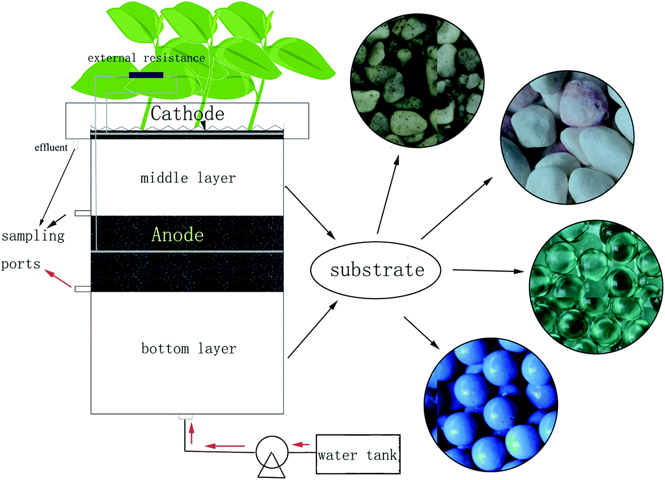 | ||
| Fig. 1 Configuration of the microbial fuel cell-coupled constructed wetland (CW-MFC). | ||
2.2 Dye wastewater
Commercial purity reactive brilliant red X-3B (ABRX3, C19H10Cl2N6Na2O7S2) was purchased from Huibang Fine Chemical Company Limited in Shanghai, China. 300 mg L−1 ABRX3 (calculate by formula weight) and 210 mg L−1 glucose were added to the medium solution (NH4Cl: 0.31 g L−1, NaH2PO4: 4.97 g L−1, Na2HPO4: 2.75 g L−1, KCl: 0.13 g L−1, NaHCO3: 3.13 g L−1, and concentrated trace element solution: 0.1 mL (ref. 16)) to form artificial wastewater. The chemical oxygen demand (COD) of the artificial wastewater was 300 mg L−1. According to previous research, this dose of glucose and ABRX3 greatly helped the ABRX3 decolorization and bioelectricity generation.132.3 Inoculation and operation
The GAC of the anode layer came from CW-MFCs, running over two years, and was used to minimize the start-up stage of CW-MFCs. All the CW substrates were immersed in 5% HCl for 2 days and washed with ultrapure water 3 times to remove the organic matter. The artificial wastewater, mentioned in Section 2.2, was pumped continuously with a peristaltic pump into the CW-MFCs, and the hydraulic retention time (HRT) was 3 days. The systems were all stable when the maximal reproducible voltages were obtained and the chrominance of effluent was stable. The real-time voltages (collected by a data acquisition module (DAM-3057 and DAM-3210, Art Technology Co. Ltd., China) every 5 min) and the effluent water quality data were collected during the entire experiment. CW-MFCs could maintain a long-term stable operation status (at least 6 months). All the experimental systems had 3 parallel experiments to ensure the repeatability of the experiments. All the experimental data, such as decolorization efficiency, glucose concentration and electrochemistry parameters, were measured in triplicate. All the experiments were conducted at a constant room temperature (25 °C ± 2 °C).2.4 Analytics and calculations
Volatile suspended solid (VSS) was used to characterize all volatile organisms caused by microbes in the substrates. The substrates were taken from the CW-MFCs and managed with ultrasonic cleaning in hyperpure water to wash off the volatile organisms. The wash water was strained through quantitative filter paper and the filter was then fired in a muffle furnace at 600 °C. The VSS was expressed as the weight of VSS per litre of substrates (g L−1).The fluorescence in situ hybridization (FISH) technique was used to calculate the microbial densities in different substrates and the densities of the electrogenic bacteria and Archaea in the anode and cathode layers. The probe for eubacteria was EUB338 (GCTGCCTCCCGTAGGAGT) and was labeled with HEX. According to a previous study, G. sulfurreducens and Beta proteobacteria were the primary electrogenic bacteria in these CW-MFCs.17 Therefore, they were chosen to detect the electrogenic bacteria in this study. The probe for G. sulfurreducens was GEO2 (GAAGACAGGAGGCCCGAAA) and was labeled with CY3 in combination with the unlabeled auxiliary probes HGEO2-1 (GTCCCCCCCTTTTCCCGCAAGA) and HGEO2-2 (CTAATGGTACGCGGACTCATCC). The probe for Beta proteobacteria was BET42a (GCCTTCCCACTTCGTTT) and was labeled with HEX. The probe of Archaea was ARCH915 (GTGCTCCCCCGCCAATTCCT) and was labeled with FITC. The slides were examined by fluorescence microscopy (Nikon ECLIPSE Ci-L, Japan) and photos were taken using a Digital Camera (Nikon DS-Ri1-U3, Japan). Fluorescence intensity was detected by Image-Pro Plus. The microbial population was counted and expressed as the number of microbes per gram of substrate (number per g).
The ABRX3 concentration was measured by the absorbance at a maximal wavelength of 538 nm detected by a spectrophotometer (Labtech 9100B PC). The decolorization efficiency of ABRX3 was calculated by monitoring the decrease in ABRX3 concentration.
The glucose concentration was measured by anthrone – H2SO4 colorimetry.
Chemical oxygen demand (COD) was measured using the potassium dichromate method (APHA method 5220).
All samples were filtered through a 0.45 μm syringe filter to remove suspended solids prior to the measurements.
Because of the complex composition of the CW-MFCs and sediment MFCs (SMFCs), cyclic voltammetry has seldom been used in the electrochemistry research of these two types of MFCs. In this study, the electricity generation performance of CW-MFCs was judged by the power density curve and polarization curve. To investigate the performance of electrodes, the anode and cathode polarization curves were also produced. The internal resistance of the anode and cathode were measured using an AC impedance technique on an electrochemical workstation (Chi660d, Shanghai Chenhua, China). The high frequency was 100![[thin space (1/6-em)]](https://www.rsc.org/images/entities/char_2009.gif) 000 Hz and the low frequency was 0.01 Hz.
000 Hz and the low frequency was 0.01 Hz.
The internal resistance of the CW-MFCs was calculated by the linear region of polarization curve, while the ohmic resistance was measured by the current interruption method. The data-collection interval during the current interruption method was 1 millisecond.
The coulombic efficiency (CE) was calculated as follows:18
 | (1) |
485 C mol−1 e−), 4 is the electron number gained by the reduction reaction of 1 mole of O2, and 32 is the molar mass of O2. Qin is the volumetric influent flow rate of CW-MFC (L s−1). ΔCOD is the COD lost in the anode.
A t-test was adopted to compare the experimental data between different groups. The P values were calculated using excel 2007. A p value < 0.01 means there is a significant difference between the groups.
3. Results and discussion
3.1 ABRX3 decolorization and glucose consumption
To show the advantage of CW-MFC on bioremediation, one CW-MFC without an external circuit connection was set as group P to compare with group A. Group P was the equivalent of a sole constructed wetland. The ABRX3 decolorization efficiencies in the bottom and anode layer of these two groups are listed in Table 1. ABRX3 could not be decolorized in the middle and cathode layer because the oxidation–reduction potentials of these two layers were too high to break the –N![[double bond, length as m-dash]](https://www.rsc.org/images/entities/char_e001.gif) N– bond in ABRX3 (ref. 19) (azo dyes can be decolorized when the oxidation–reduction potential is below −50 mV; the oxidation–reduction potentials of the middle and cathode layer were higher than −50 mV). Therefore, the decolorization took place only in the bottom and the anode layer. There was no significant difference in the ABRX3 decolorization efficiencies of the bottom layer of group A and P. However, the decolorization efficiency of the anode layer of group A was 16.45% higher than that of group P. This shows that the closed circuit of CW-MFC can promote ABRX3 decolorization. Other studies have also reported the improvement of MFC on pollutant disposal.2,20 The ABRX3 was reduced in the anode; therefore, ABRX3 required electrons from the co-substrate. The closed circuit of CW-MFC significantly stimulated the reduction of ABRX3, mostly because the closed circuit accelerated electron flow and made ABRX3 accept electrons more easily.
N– bond in ABRX3 (ref. 19) (azo dyes can be decolorized when the oxidation–reduction potential is below −50 mV; the oxidation–reduction potentials of the middle and cathode layer were higher than −50 mV). Therefore, the decolorization took place only in the bottom and the anode layer. There was no significant difference in the ABRX3 decolorization efficiencies of the bottom layer of group A and P. However, the decolorization efficiency of the anode layer of group A was 16.45% higher than that of group P. This shows that the closed circuit of CW-MFC can promote ABRX3 decolorization. Other studies have also reported the improvement of MFC on pollutant disposal.2,20 The ABRX3 was reduced in the anode; therefore, ABRX3 required electrons from the co-substrate. The closed circuit of CW-MFC significantly stimulated the reduction of ABRX3, mostly because the closed circuit accelerated electron flow and made ABRX3 accept electrons more easily.
| Group | X-3B decolorization efficiency (%) | |
|---|---|---|
| Bottom layer | Anode layer | |
| Group A | 54.61 | 38.09 |
| Group P | 50.34 | 21.64 |
The ABRX3 decolorization efficiencies and glucose removal efficiencies in the CW-MFCs filled with different substrates are shown in Fig. 2. According to Fig. 2A, substrate microbes had a strong influence on ABRX3 decolorization. In the bottom layer of the group A, the ABRX3 decolorization efficiency was the highest, which reached up to 54.61%, while in the bottom layer of group C, the ABRX3 decolorization efficiency was the lowest, which reached 12.57%. The ABRX3 decolorization efficiencies in the bottom layers of group D and B were 20.96% and 16.83%, respectively.
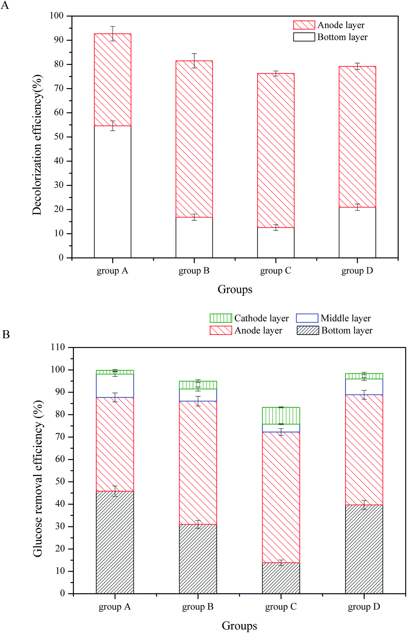 | ||
| Fig. 2 ABRX3 decolorization and glucose consumption in CW-MFCs with different substrate biomasses: (A) ABRX3 decolorization, (B) glucose consumption. | ||
In the anode layer, groups B and C had similar ABRX3 decolorization efficiencies; they were 64.66% and 63.39%, respectively (P value > 0.05). The ABRX3 decolorization efficiency of group D was lower than the abovementioned two values, which was 58.25% (P < 0.01). The ABRX3 decolorization efficiency of group A was the lowest, which was only 38.09%.
As shown in Fig. 2B, glucose was mostly consumed in the bottom and the anode layer, which is consistent with previous research.21 Moreover, 45.83% of the glucose was removed in the bottom layer of group A, while only 13.86% of the glucose was removed in the same part of group C. Furthermore, 31.02% and 39.67% of the glucose was removed by the bottom layers of the groups B and D, respectively. The anode layer of group A consumed 41.89% of the glucose, which is similar to the bottom layer. However, the anode layer of other three groups consumed more glucose than the bottom layer; the glucose removal efficiencies in the anode layer of group B, C and D were 55.03%, 60.76% and 47.82%, respectively. In the middle and the cathode layer of all CW-MFCs, the glucose consumption was limited and there were no significant differences in glucose consumption between CW-MFCs.
To measure the substrate biomass of four CW-MFCs, VSS and FISH were used to determine the volatile organisms and the eubacteria density. As shown in Fig. 3, the substrates had strong effects on the substrate biomass. In the bottom layer, group A showed the highest VSS and eubacteria density of 0.453 g L−1 and 2.931 × 10⁸ g−1, respectively. The biomass of group D was less than that in group A, the VSS and eubacteria densities were 0.290 g L−1 and 1.786 × 10⁸ g−1, respectively. The biomass of group B was lower than that of group D and the VSS and eubacteria density were 0.177 g L−1 and 1.465 × 10⁸ g−1, respectively. Group C had the lowest biomass. The VSS and eubacteria density were 0.002 g L−1 and 2.75 × 10⁷ g−1, respectively. The situation in the middle layer was similar to the bottom layer. Group A had the highest biomass among the four CW-MFCs, while group C had the lowest. On the other hand, for all the CW-MFCs, the biomass in the bottom layers was much higher than in the middle layers.
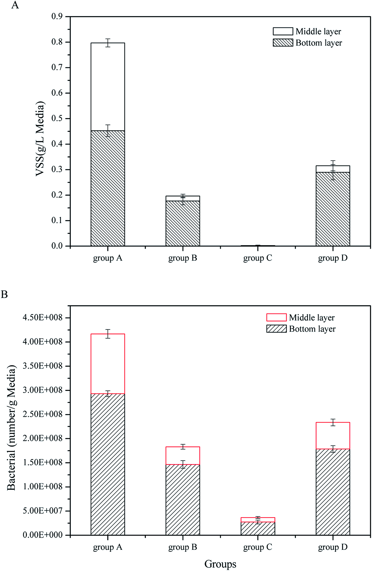 | ||
| Fig. 3 Substrate microbial biomass in CW-MFCs filled with different substrates: (A) VSS, (B) bacterial number. | ||
In the up-flow CW-MFCs, the bottom layer contacted the artificial wastewater first, which made the microbes in the bottom layer receive more nutrition than the microbes in the middle layer. Fig. 2B shows that the bottom layer consumed more glucose than the middle layer. Therefore, the bottom layer of CW-MFCs had the highest substrate biomass. Different substrates had a great influence on the substrate biomass. The substrates used in this study had similar porosities but different surfaces. The coarsest particle was the gravels (group A), followed by the biological ceramic (group D). The surface of the screes was smoother than the two mentioned above, while the glass bead had the smoothest surface (settled as group C). A rough surface was beneficial to the adhesion and growth of microbes, and it enhanced the VSS in the substrates.
The experimental results indicated that in the bottom layer, the substrate biomass had a significant influence on the ABRX3 decolorization and glucose consumption. The decolorization efficiencies and glucose removal efficiencies increased with increasing substrate biomass. In the bottom layer, the mechanism of ABRX3 decolorization was biodegradation; glucose is a type of co-substrate that is necessary for the decolorization of the azo dye.22,23 More microbial biomass would benefit the ABRX3 decolorization. Significantly, less ABRX3 was decolorized in the bottom layer and more was decolorized in the anode layer, which is similar to glucose consumption. This is because the anode material, GAC, was an excellent material for microbial growth; the glucose that was not consumed in the bottom layer would come up to the anode layer and promote the growth of anode microbes and ABRX3 decolorization. According to a previous study,13 ABRX3 decolorization in the anode layer of CW-MFCs was not only because of the anaerobic biological reduction but was also promoted by the electrode reaction of CW-MFCs. However, the total ABRX3 decolorization efficiencies of groups B, C and D were lower than that of group A; even the anode ABRX3 decolorization efficiencies of groups B, C and D were much higher than that of group A. For group A, the bottom layer contributed to the majority of ABRX3 decolorization. The decolorization efficiency of group A was the highest of all the four CW-MFCs, reaching 92.7%. The decolorization efficiency of group C was only 76.3%. This indicated that the promotion of electrode reaction on the decolorization was insufficient to offset the contribution of bottom layer biological reduction. Therefore, from a decolorization point of view, the substrate biomass has positive effects on promoting the azo dye decolorization efficiencies. Thus, the substrate biomass had a positive significance in enhancing the azo dye decolorization. On the other hand, in the anode layer of CW-MFCs, glucose was not only used for ABRX3 decolorization, but also for bioelectricity generation.24,25 Therefore, the excessive consumption of glucose in the bottom layer may cause a lack of glucose in the anode layer, which is disadvantageous to electricity generation of the anode. The over inhibited electricity generation would finally be disadvantageous to ABRX3 decolorization.
3.2 Bioelectricity generation and electrode performance
To investigate the electricity generation performance of CW-MFCs with different substrate biomass, the external resistance was changed from 10 Ω to 100000 Ω to gain the power density and the polarization curves of full CW-MFC (Fig. 4A), while the polarization curves of the anodes and cathodes were tested for electrode performance monitoring (Fig. 4B). The ohmic resistance was separated from the other resistances via the current interruption method, and the anode and cathode internal resistances were measured.
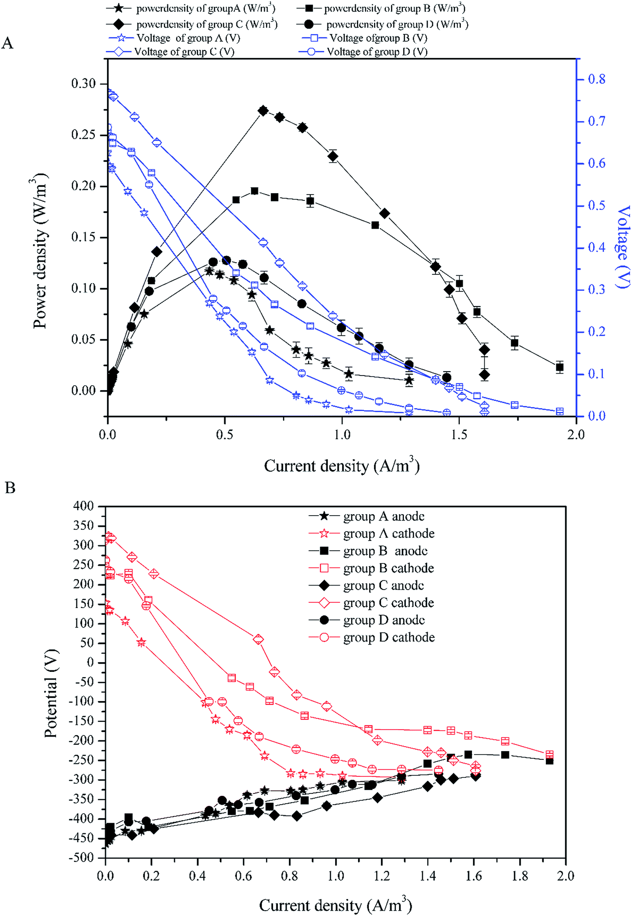 | ||
| Fig. 4 Power density curves and the polarization curves: (A) power density curves and polarization curves of full CW-MFCs, (B) polarization curves of the anodes and cathodes. | ||
According to Fig. 4A, the highest maximum power density was 0.274 W m−3 in group C (with current density of 0.664 A m−3). The maximal power density of group B was second to group C and was 0.256 W m−3 (with current density of 0.717 A m−3). The maximal power density of groups D and A were lower than the above two, which were 0.128 W m−3 (with current density of 0.506 A m−3) and 0.117 W m−3 (with current density of 0.434 A m−3), respectively. Fig. 5 shows the internal resistance distribution of each CW-MFC. There were significant differences in the internal resistance of CW-MFCs with different substrate biomass. The internal resistance of group A was the highest (1471.20 Ω), and the internal resistance of group D, B and C was 851.19 Ω, 726.94 Ω and 651.9 Ω, respectively. However, there were no significant differences in ohmic resistance because the CW-MFCs shared the same structure, electrode materials and electrically conductive solution. This was only a small part of the internal resistance.26,27 The ohmic resistance of groups A, D, B and C was 174.31 Ω, 141.26 Ω, 146.81 Ω, and 164.63 Ω, respectively. The CW-MFCs had low CE, and the highest CE was gained by group C at 1.68%. The CE of group A, D, and B was 0.87%, 1.58% and 1.35%, respectively.
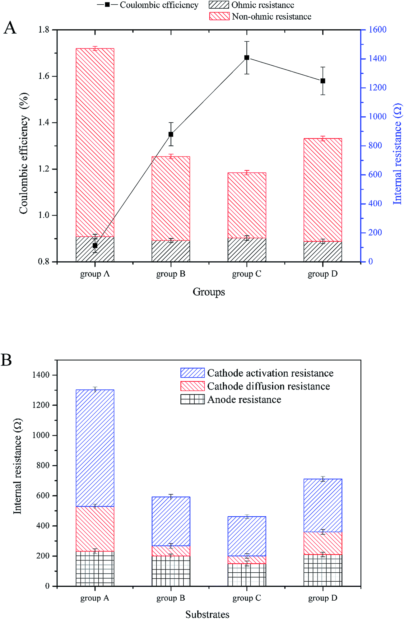 | ||
| Fig. 5 Coulombic efficiency and internal resistance distribution profiles: (A) coulombic efficiency and internal resistance, (B) anode and cathode internal resistance. | ||
The substrate biomass had a significant influence on the bioelectricity generation performance. The more the substrate biomass, the lower the power density. The CW-MFC with less substrate biomass had better bioelectricity generation performance. One of the reasons for this phenomenon was the co-substrate consumption in the bottom layer. According to 3.1, more glucose was consumed in the bottom layer of the CW-MFC, which had more biomass. This may lead to a lack of co-substrate in the anode layer. The electricity generation may decrease when there was not enough nutrients for electrogenic bacteria. Research has shown that higher concentrations of co-substrate would benefit electricity generation.28,29 As showed in Fig. 4B, the anode polarization was a little greater in the CW-MFCs with more substrate microbial biomass when the current density was higher than 0.5 A m−3. However, obviously the cathode was the main constraint on CW-MFC electricity generation performance because the cathode polarizations of the CW-MFCs with more substrate biomass were significantly greater than the CW-MFCs with less substrate biomass. The open circuit cathode potential of the CW-MFCs with more substrate biomass was also lower than that with less substrate biomass. On the other hand, the CW-MFCs with more substrate microbial biomass had higher non-ohmic resistance. The internal resistance consisted of the activation resistance, ohmic resistance and concentration resistance, while the polarization curve also had three parts: activation over the potential area during a low current density, ohmic over potential area during a middle current density and concentration over potential area during a high current density.26 Surprisingly, the slopes of the concentration over potential in CW-MFCs were larger than that of the ohmic over potential, and the slope increased with increasing substrate biomass. The concentration over potential in the MFCs was caused by the diffusion resistance of reactant between the electrode and the electrolyte, which did not significantly affect the polarization of electrodes.26 In some studies, however, the concentration over potential curve and the ohmic over potential curve had a similar slope,30,31 which was different from this study. This indicated that the proportion of concentration resistances in the internal resistances of this study were smaller than other studies. In contrast, the activation over potential areas were short and sharp, which indicated that the activation resistance played an important role in the internal resistance. The activation resistance came from the electrochemical reaction in the electrodes.26 Thus, if the electrochemical reaction controlled the reaction speed of CW-MFCs, the influence of diffusion resistance may become smaller. According to Fig. 5B, the cathode resistance contributed the most to the internal resistance of CW-MFCs. Group A, which had the lowest power-generation, had the highest cathode resistance of 1070.41 Ω. The cathode resistance of group C was lowest at 312.05 Ω, and the power-generation of group C was the highest above all CW-MFCs. The anode resistance, by comparison, had a smaller difference between all CW-MFCs. This indicated that the reaction rate-determining chamber of the system was the cathode. In this study, the activation resistance of the cathode was the main reason for the performance degradation of CW-MFCs. As the cathode activation resistance of group A was 772.87 Ω, the cathode diffusion resistance was only 297.54 Ω. Other groups had the same situation as group A. The cathode activation resistance of groups B, C and D was 323.37, 261.73 and 261.73 Ω, respectively, while the cathode diffusion resistance was only 67.45, 50.32 and 50.32 Ω, respectively. This shows that the cathode reaction has a great influence on the cathode performance. The cathode performance degradation was significantly greater in the CW-MFCs with more substrate biomass. This may be because the substrate biomass in the middle layer consumed more nutrients, which depleted the cathode of nutrients, and inhibited the growth of microbes in the cathode. The cathode biofilm in the sediment MFC could promote the oxidation reduction rate32 and the electricity generation.33,34 This may explain the cathode performance inhibition. Because the cathode performance played an important role in the entire CW-MFC performance, efforts should be made to enhance the cathode performance.
The CEs of this study were very low, which is consistent with previous studies.5,8,35 CW-MFCs often have low CEs, which may be due to the large anode volume and high internal resistance. The CE of CW-MFC in this study decreased with increasing substrate biomass. This may be because the microbes in the substrate consumed too much nutrients, which depleted the anode layer of nutrients.
3.3 Electrogenic bacteria and Archaea in the anode and the cathode
In previous research, we found electrogenic bacteria G. sulfurreducens and Beta proteobacteria controlled the operation performance for power generation, and the purpose of CW-MFC was to promote the pollutant degradation by power generation. Therefore, the FISH technique was employed to investigate the influence of the substrate biomass on electrogenic bacteria and Archaea in the anode and cathode layers.According to Fig. 6A and Fig. 3B, for all CW-MFCs, the anode layers had the highest bacterial abundance, followed by the cathode layers, which was attributed to the advantage of GAC for bacterial adhesion and growth.36 Group C had the highest anode bacterial abundance of 2.029 × 10⁹ g−1, while the bacterial abundance in the anode of groups B, D and A was 1.639 × 10⁹ g−1, 1.602 × 10⁹ g−1 and 1.488 × 10⁹ g−1, respectively. The bacterial abundance of the cathode layer was low, and group C had the highest bacterial abundance of 6.960 × 10⁸ g−1, while the bacterial abundance in the cathode of group B, D and A was 5.403 × 10⁸ g−1, 4.259 × 10⁸ g−1 and 2.885 × 10⁸ g−1, respectively. The biomass in the substrates exerted a considerable influence on the bacterial abundance in the anode layer of the CW-MFCs. CW-MFCs with more substrate microbial biomass had less anode bacteria. This may be due to the consumption of the co-substrate by substrate biomass in the bottom layer (Fig. 2B), which causes the limitation of the nutrients to the bacteria in the anode layer.
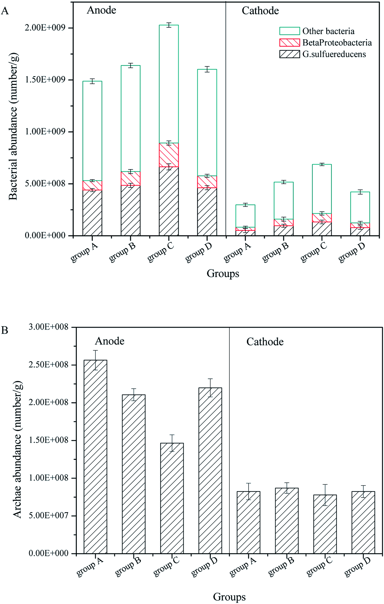 | ||
| Fig. 6 Bacteria and Archaea in the anode and cathode of CW-MFCs with different substrate microbial biomass: (A) bacteria, (B) Archaea. | ||
Significantly, the bacterial abundance in the cathode layer showed the same tendency as in the anode. This indicates that the CW-MFCs with more substrate biomass would have a lower cathode biomass. This may inhibit the cathode degradation performance, as mentioned in 3.2.
Regarding electrogenic bacteria, the proportions of G. sulfurreducens and Beta proteobacteria in the anode layers were approximately 30% and 10%, respectively. In the cathode layers, the proportions of G. sulfurreducens and Beta proteobacteria were approximately 18% and 11%, respectively. According to the bacterial abundance mentioned before, the CW-MFCs with more substrate microbial biomass had less anode electrogenic bacteria, which might explain their lower bioelectricity generation. The proportions of G. sulfurreducens were higher in the anode layer than in the cathode layer, while the Beta proteobacteria had similar proportions both in the anode and cathode layers. These results suggest that the CW-MFC anode promoted the growth of G. sulfurreducens, but had a small influence on the Beta proteobacteria.
Regarding Archaea, as shown in Fig. 3B, the anode layers had more Archaea than the cathode layers. The anode layer of group A had the highest Archaea abundance of 2.564 × 10⁸ g−1, which decreased with increasing substrate biomass. The anode Archaea abundance of groups D, B, and C was 2.198 × 10⁸ g−1, 2.106 × 10⁸ g−1 and 1.465 × 10⁸ g−1, respectively. There was no significant difference among the cathode Archaea abundances, and the differences were between 7.784 × 10⁸ g−1 and 8.242 × 10⁸ g−1. Archaea in the anode may compete with the electrogenic bacteria for nutrients. Therefore, the abundance of Archaea may decrease when the electrogenic bacteria abundance is high. Archaea include Methanogenus, Thermoacidophile and particularly Halophilic Archaea, the environment of CW-MFCs in this study is only suitable for Methanogenus, which is a type of anaerobic bacteria. Therefore the abundance of Archaea in the cathode layer was low.
4. Conclusions
For the CW-MFCs, the biomass in the wetland substrates had noticeable influence on the azo dye decolorization and bioelectricity generation, which were not considered in previous studies. The microbes in the substrates might compete with the microbes in the anode and cathode for nutrients, which may reduce the bioelectricity generation. The CW-MFCs with less substrate biomass had better electricity generation performance. Group C had the highest maximal power density of 0.274 W m−3 and a current density of 0.664 A m−3. However, the substrate biomass benefited the azo dye decolorization. ABRX3 had the highest decolorization efficiency of 92.7% in group A. The substrate biomass might disturb the electrode performance of CW-MFC. One reason was the competition between the bottom layer microbes and the anode layer microbes. However, the cathode performance was critical for improving the CW-MFC performance. On the other hand, the CW-MFCs with more substrate microbial biomass had fewer anode and cathode microbes. Therefore, low cathode performance may be noticed because of the high activation resistance. The low cathode microbe abundance may lead to a low activation reaction rate. The conclusions of this study have significance on the applications of MFCs in natural environments because MFCs built in the natural environments, such as rivers, lakes and coastal beaches, face complex substrates, significantly influence the performance of MFCs. In future studies, cluster analysis will be employed and the species diversity index of these different CW-MFCs will be used to examine the effects of microbes in the CW-MFCs on the power generation and pollutant degradation.Acknowledgements
We thank the National Science Foundation of China (Grants No. 21277024), the Fundamental Research Funds for the Central Universities and the Scientific Research Foundation of Graduate School of Southeast University for their financial support.References
- C.-S. He, Z.-X. Mu, H.-Y. Yang, Y.-Z. Wang, Y. Mu and H.-Q. Yu, Chemosphere, 2015, 140, 12–17 CrossRef CAS PubMed.
- B. Hou, J. Sun and Y.-y. Hu, Bioresour. Technol., 2011, 102, 4433–4438 CrossRef CAS PubMed.
- Z. Li, X. Zhang, J. Lin, S. Han and L. Lei, Bioresour. Technol., 2010, 101, 4440–4445 CrossRef CAS PubMed.
- A. Ghrabi, L. Bousselmi, F. Masi and M. Regelsberger, Water Sci. Technol., 2011, 63, 3006–3012 CrossRef PubMed.
- L. Doherty, Y. Zhao, X. Zhao and W. Wang, Chem. Eng. J., 2015, 266, 74–81 CrossRef CAS.
- S. Liu, H. Song, S. Wei, F. Yang and X. Li, Bioresour. Technol., 2014, 166, 575–583 CrossRef CAS PubMed.
- V. G. Gude, J. Cleaner Prod., 2016, 122, 287–307 CrossRef CAS.
- A. K. Yadav, P. Dash, A. Mohanty, R. Abbassi and B. K. Mishra, Ecol. Eng., 2012, 47, 126–131 CrossRef.
- Y. Zhao, S. Collum, M. Phelan, T. Goodbody, L. Doherty and Y. Hu, Chem. Eng. J., 2013, 229, 364–370 CrossRef CAS.
- Z. Fang, H.-L. Song, N. Cang and X.-N. Li, Bioresour. Technol., 2013, 144, 165–171 CrossRef CAS PubMed.
- C. Corbella, M. Garfí and J. Puigagut, Sci. Total Environ., 2014, 470, 754–758 CrossRef PubMed.
- S. Srikanth, T. Pavani, P. Sarma and S. V. Mohan, Int. J. Hydrogen Energy, 2011, 36, 2271–2280 CrossRef CAS.
- Z. Fang, H.-l. Song, N. Cang and X.-n. Li, Biosens. Bioelectron., 2015, 68, 135–141 CrossRef CAS PubMed.
- Y. Zhang and I. Angelidaki, Biosens. Bioelectron., 2012, 35, 265–270 CrossRef CAS PubMed.
- J. Laber, R. Haberl, R. Perfler and G. Langergraber, in Proceedings of the 7th International Conference on Wetland Systems for Water Pollution Control, Lake Buena Vista, Florida, 2000, pp. 937–945 Search PubMed.
- H. Liu, S. Cheng, L. Huang and B. E. Logan, J. Power Sources, 2008, 179, 274–279 CrossRef CAS.
- T. Li, Z. Fang, R. Yu, X. Cao, H. Song and X. Li, Environ. Technol., 2015, 1–17 Search PubMed.
- N. Uría, X. Muñoz Berbel, O. Sánchez, F. X. Muñoz and J. Mas, Environ. Sci. Technol., 2011, 45, 10250–10256 CrossRef PubMed.
- K. Bromley-Challenor, J. Knapp, Z. Zhang, N. Gray, M. Hetheridge and M. Evans, Water Res., 2000, 34, 4410–4418 CrossRef CAS.
- J. Sun, Y.-y. Hu, Z. Bi and Y.-q. Cao, Bioresour. Technol., 2009, 100, 3185–3192 CrossRef CAS PubMed.
- X. Li, J. Southeast Univ., 2012, 28, 175–178 CAS.
- M. S. Khehra, H. S. Saini, D. K. Sharma, B. S. Chadha and S. S. Chimni, Dyes Pigm., 2006, 70, 1–7 CrossRef CAS.
- S.-A. Ong, E. Toorisaka, M. Hirata and T. Hano, Sep. Purif. Technol., 2005, 42, 297–302 CrossRef CAS.
- P. Singh, R. Sanghi, A. Pandey and L. Iyengar, Bioresour. Technol., 2007, 98, 2053–2056 CrossRef CAS PubMed.
- K. Rabaey, G. Lissens, S. D. Siciliano and W. Verstraete, Biotechnol. Lett., 2003, 25, 1531–1535 CrossRef CAS PubMed.
- B. E. Logan, Microbial fuel cells, John Wiley & Sons, 2008 Search PubMed.
- Z. Du, H. Li and T. Gu, Biotechnol. Adv., 2007, 25, 464–482 CrossRef CAS PubMed.
- S. Cheng and B. E. Logan, Bioresour. Technol., 2011, 102, 4468–4473 CrossRef CAS PubMed.
- C. Corbella, M. Guivernau, M. Viñas and J. Puigagut, Water Res., 2015, 84, 232–242 CrossRef CAS PubMed.
- Y. Luo, R. Zhang, G. Liu, J. Li, B. Qin, M. Li and S. Chen, Bioresour. Technol., 2011, 102, 3827–3832 CrossRef CAS PubMed.
- Y. Feng, H. Lee, X. Wang, Y. Liu and W. He, Bioresour. Technol., 2010, 101, 632–638 CrossRef CAS PubMed.
- Ø. Hasvold, H. Henriksen, E. Melv, G. Citi, B. Ø. Johansen, T. Kjønigsen and R. Galetti, J. Power Sources, 1997, 65, 253–261 CrossRef.
- A. Bergel, D. Féron and A. Mollica, Electrochem. Commun., 2005, 7, 900–904 CrossRef CAS.
- K. Rabaey, S. T. Read, P. Clauwaert, S. Freguia, P. L. Bond, L. L. Blackall and J. Keller, ISME J., 2008, 2, 519–527 CrossRef CAS PubMed.
- S. Liu, H. Song, X. Li and F. Yang, Int. J. Photoenergy, 2013, 2013 Search PubMed.
- Y. Sun, J. Wei, P. Liang and X. Huang, Bioresour. Technol., 2011, 102, 10886–10891 CrossRef CAS PubMed.
| This journal is © The Royal Society of Chemistry 2017 |