 Open Access Article
Metal/TiO2 hierarchical nanocomposite arrays for the remarkable enhancement of photocatalytic activity
Kun Donga,
Lu Huangb,
Changzheng Wang *a,
Ping Xua,
Yajun Zhanga,
Cuimin Fenga,
Tao Chena,
Qiang Wang*c and
Yang Zhang*d
aKey Laboratory of Urban Stormwater System and Water Environment, Ministry of Education, Beijing University of Civil Engineering and Architecture, Beijing 100044, PR China. E-mail: changzhwang@163.com; Tel: +86 10 68322131
bLiupanshui Normal University, Liupanshui 553004, PR China
cLaboratory of Micro- and Nano-sized Functional Materials, Capital Normal University, Beijing 100048, PR China. E-mail: qwchem@gmail.com; Tel: +86 10 68902523
dBeijing Institute of Nanoenergy and Nanosystems, Chinese Academy of Sciences, National Center for Nanoscience and Technology (NCNST), Beijing 100083, PR China. E-mail: zhangyang@binn.cas.cn; Tel: +86 10 82854792
First published on 15th March 2017
Abstract
Metal/TiO2 hierarchical nanocomposite arrays were assembled by the deposition of aggregated TiO2 nanoparticles on anodic aluminum oxide templates and the subsequent loading of metal nanoparticles by electrochemical deposition. The as-prepared samples were characterized by X-ray diffraction, scanning electron microscopy, transmission electron microscopy, energy dispersive X-ray spectroscopy and ultraviolet-visible spectroscopy. The photocatalytic activities of the as-synthesized catalysts were evaluated for the degradation of organic dyes. Our experimental results demonstrated that the greatly improved photocatalytic efficiency of the metal/TiO2 hierarchical nanocomposite arrays resulted from their high surface area and symmetrical arrangement. As a prospective approach for wastewater purification, our work not only enriches the synthetic methodology for TiO2, but also provides valuable knowledge about nanosized photocatalysts.
1. Introduction
Pioneering works in the early 1970s revealed that hydrogen can be produced by photocatalytic water splitting over a TiO2 semiconductor under UV irradiation, leading to the broad investigation of nanosized TiO2 for in vivo imaging, cancer therapy, protein separation/purification, dye-sensitized solar cells, perovskite solar cells and bactericides.1–11 Utilizing sustainable solar energy is of paramount importance in developing photocatalysts for wastewater treatment. In fact, as a kind of typical azo dyestuff, methyl orange (MO) is one of the main substances in the wastewater industry, and its removal has drawn widespread attention.12,13 The effective harvesting of solar energy plays an essential role in developing photocatalysts; other important characteristics include convenient synthesis, scalable production and good stability. Previous works demonstrated that TiO2-based photocatalysts are potential candidates for the decomposition of organic pollutants in wastewaters.14–16 Great efforts have been made to synthesize nanosized TiO2 with controllable morphology. However, undoped TiO2 can be utilized as a UV-light-active photocatalyst due to its wide band gap (∼3.20 eV).17,18 However, the rapid recombination of photo-generated electron–hole pairs results in low degradation efficiency, which extremely limits its photocatalytic applications. There are two potential approaches to solve this problem: synthesizing TiO2-based nanomaterials with high specific surface areas and preparing TiO2-based nanocomposites. On one hand, nanosized TiO2 with a complex structure has improved the photocatalytic activity by increasing the number of surface-active centres. Zhu and co-workers assembled TiO2 nanoparticles (NPs) with sizes of 4–5 nm into spherical aggregates through the chemical reaction between cyclohexane and cetyltrimethylammonium.19 Yang and co-workers first reported the preparation methods of hierarchically ordered metal oxide nanomaterials, which significantly broaden the assembly strategies for porous nanomaterials.20 Therefore, TiO2 NPs can be encapsulated into nanochannels when anodic aluminum oxide (AAO) templates are immersed into the TiO2 sol solution due to capillary action. The TiO2 NPs preferably deposit on the wall of the AAO template and then gather in the pore canal.21,22 Regardless of the sizes and shapes of the TiO2 NPs, the controllable synthesis of TiO2 hierarchical nanoarrays (HNAs) can be achieved by tuning the concentration, immersion time and reaction temperature of the TiO2 sol.23–25 On the other hand, several metal (Ag, Au, and Pt) loading routines have been used to improve the photoresponse of nanosized TiO2, such as chemical reduction, ion impregnation, impregnation-reduction, photodeposition and electrochemical deposition.26–39 In particular, metal ions can be dispersed uniformly on the surface of TiO2 permeated in the gap between TiO2 aggregates using electrochemical deposition.In the past decade, extensive efforts have been directed towards the photodegradation of organic pollutants in a highly efficient manner.14,40–47 Nevertheless, quite a few studies have reported the photodegradation of organic dyes using TiO2 photocatalysts with hierarchical nanostructures.48–51 In the initial process of photocatalytic degradation, electron–hole pairs are generated under light illumination, separated on the semiconductor surface, and then reacted with organic chemicals in solution.52–55 During photocatalytic progress, the enhanced performance can generally be ascribed to the increased reactive surface area or reduced recombination of photo-generated electron–hole pairs, which are regarded as different contributors to the photocatalytic efficiency.56,57 In principle, the modification of the photocatalyst surface with metal NPs will facilitate charge-carrier transport and reduce charge-carrier recombination.58
In this work, we present a novel approach to fabricate metal/TiO2 hierarchical nanocomposite arrays (HNCAs), and Ag and Au are selected as representative metals. First, TiO2 HNAs were assembled via the aggregation of TiO2 NPs with the help of an AAO template. Second, Ag (or Au) was loaded on the TiO2 HNAs by electrochemical deposition. The synthetic strategy for complex nanostructured TiO2 provides an impressive pathway for light response through the controllable loading of metal NPs. The as-prepared metal/TiO2 HNCA samples were examined for the photocatalytic degradation of MO under UV light illumination. Our experimental results revealed that the photocatalytic efficiency of the metal/TiO2 HNCAs was enhanced comparison to the TiO2 HNAs, suggesting promising prospects for the degradation of organic pollutants.
2. Experimental section
2.1 Materials
All reagents in this work were used as received without further purification. Titanous sulfate [Ti(SO4)2], hexadecyl trimethyl ammonium bromide (C19H42BrN, CTAB), oxalic acid, cyclohexane, ethyl alcohol, acetone, deionized water, concentrated sulfuric acid (H2SO4, 98%) and MO were purchased from Sinopharm Chemical Reagent Beijing Co. Ltd. AAO templates were prepared by the anodization of aluminum plates in oxalic acid solution.2.2 Preparation of TiO2 NPs
TiO2 NPs were prepared by a microemulsion method, and the procedure is briefly described here.25 First, 2.0 g CTAB was dissolved in 100 mL distilled water. Second, 2 mL concentrated H2SO4, 2.5 mL cyclohexane and 1 g Ti(SO4)2 were sequentially added into the CTAB solution, which was then poured into a 250 mL round-bottom flask. After stirring the abovementioned mixture for 1 h, a transparent microemulsion was obtained. Third, a white precipitate was obtained after refluxing for 1 h (at 100 °C). Fourth, the precipitate was centrifuged at a rotation rate of 10![[thin space (1/6-em)]](https://www.rsc.org/images/entities/char_2009.gif) 000 rounds per s and rinsed sequentially with deionized water, ethanol and acetone. To remove unreacted chemicals and other impurities, the washing process was conducted three times. Finally, the product was collected by drying the sediment at 40 °C for 6 h. The as-synthesized sample, which was in the form of a white powder, in agreement with previous reports, was dispersed in ethanol solution.59–61
000 rounds per s and rinsed sequentially with deionized water, ethanol and acetone. To remove unreacted chemicals and other impurities, the washing process was conducted three times. Finally, the product was collected by drying the sediment at 40 °C for 6 h. The as-synthesized sample, which was in the form of a white powder, in agreement with previous reports, was dispersed in ethanol solution.59–61
2.3 Preparation of TiO2 HNAs
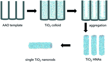
As shown in Scheme 1, the assembly of aggregated TiO2 NPs was carried out according our previous work. A homemade AAO template was fabricated by a two-step anodization process. The AAO template with pore sizes between 80 and 100 nm was employed. Briefly, a gold film was deposited on one side of the AAO template and heated for 5 min to block one side of the through-hole AAO template, which was convenient for the assembly of TiO2. The AAO template was then immersed in an ethanol solution of TiO2 colloids (0.5 mg/100 mL) for 24 h at room temperature. In fact, the deposition of the TiO2 NPs on the channel walls was driven by electrostatic attraction. The AAO template was finally removed by dissolving it in 6 M NaOH aqueous solution, and the resulting sample was then washed several times with deionized water. Longer lengths and higher specific surface areas of the TiO2 HNAs can be conveniently obtained by extending the deposition time.2.4 Preparation of metal/TiO2 HNCAs
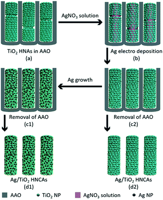
The aggregated TiO2 NPs served as the building blocks to assemble TiO2 HNAs and metal/TiO2 HNCAs. The Ag/TiO2 HNCAs were synthesized by facile electrochemical deposition method. In a three-electrode system, the TiO2 HNAs was used as the working electrode, Ag/AgCl as the reference electrode and the Pt wire as the counter electrode. The system was immersed in an AgNO3 aqueous solution with a voltage of −0.6 V, and the deposition time was set to 20 min. After polishing the redundant TiO2 NPs, dissolving the AAO template with 6 M NaOH and washing with deionized water, the synthesis of Ag/TiO2 HNCAs was achieved (Scheme 2). For the synthesis of Au/TiO2 HNCAs, the electrolyte was switched to HAuCl4, and the deposition potential was set to −0.4 V accordingly.2.5 Characterization
The crystal structures of the as-synthesized samples were characterized by X-ray diffraction (XRD). The morphologies and sizes of the samples were investigated by scanning electron microscopy (SEM, Hitachi S4800) with energy dispersive X-ray spectrometry (EDX) and transmission electron microscopy (TEM, JEOL JEM-2100F). A UV-Vis spectrometer (Hitachi U-3010) was used to study the optical properties of the samples. X-ray photoelectron spectroscopy (XPS) measurements were performed using a Thermo Fisher Scientific USA ESCA Lab250 spectrometer with monochromatic Al K-alpha X-rays, a hemispherical analyzer and a sample stage with multi-axial adjustment to obtain the compositions of the sample surfaces. The UV-Vis diffuse reflectance spectra were obtained using a PerkinEImer Lambda 600S UV/Vis spectrometer equipped with an integrating sphere assembly. The spectra were recorded at room temperature in air from 200 to 800 nm. The photocatalytic properties of the photocatalyst materials were measured using an ultraviolet and visible spectrophotometer (DR6000, HACH).2.6 Photocatalytic activities
The photocatalytic performances of the aggregated TiO2 NPs, TiO2 HNAs, and metal/TiO2 HNCAs were investigated. For all the photocatalysts, the photocatalytic degradation process was carried out in a 100 mL quartz tube under UV light illumination (UV lamp, 300 W). The temperature was kept at ambient temperature with the assistance of cooling water. A UV-Vis spectrophotometer was used to record the absorption spectra of the MO solutions after the centrifugation of TiO2. The residual concentrations of the MO solutions were determined by the characteristic absorption peak at 462 nm. To achieve the optimum photocatalytic conditions of the as-prepared samples, the amount of photocatalyst was varied from 20 to 50 mg L−1. The absorbance of the testing solution was measured for 1 h to evaluate the decomposition rate of MO. At particular time intervals, aliquots were withdrawn from the system, and the TiO2 NPs were separated from the solution by centrifugation. The residual MO solution was used to characterize the concentration by recording its absorbance intensity.3. Results and discussion
3.1 Structural and composition analysis
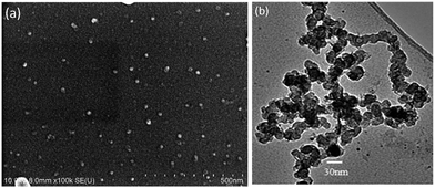
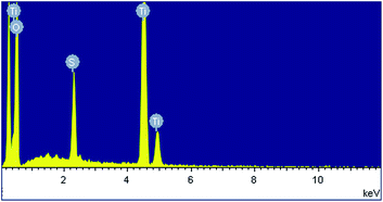
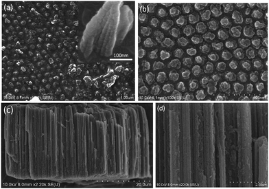
Fig. 1a shows a relatively low-magnification SEM image that reveals the overall morphology of the aggregated TiO2 NPs. As shown in Fig. 1b, TEM characterization reveals that TiO2 NPs with diameters ranging from 20 to 30 nm were synthesized. The cationic surfactant CTAB on the surfaces of the TiO2 NPs effectively restricted particle growth, thus preventing excessive aggregation. Fig. 2 shows the existence of Ti (32.04%) and O (63.15%) elements in the as-prepared sample. The peak of S originates from Ti(SO4)2 and concentrated H2SO4.TiO2 HNAs with mesoporous aggregated NPs can be seen in Fig. 3. As deposition times less than 12 h, aggregated TiO2 NPs directly assembled into the AAO template and formed nanowire arrays with heights of ∼200 nm. Extending the deposition time to 36 h, highly oriented TiO2 HNAs with longer lengths and larger surface areas can be observed after the removal of the AAO template. The increased surface area of the TiO2 HNAs may facilitate the photocatalytic degradation of organic pollutants, which will be discussed below.
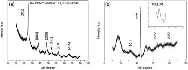
The XRD patterns of the aggregated TiO2 NPs and TiO2 HNAs are presented in Fig. 4. The characteristic diffraction peaks at 25.306°, 37.800°, 48.039°, 55.064°, 62.692°, and 75.055° can be indexed to the crystal planes of (101), (004), (200), (211), (204) and (215), respectively, indicating the formation of anatase TiO2. The morphologies and sizes of the TiO2 NPs were characterized by SEM and TEM, respectively. In fact, the TiO2 HNAs possess high surface areas and large numbers of active centres, which can be utilized to load metals into the interior spaces of the complex nanostructures.
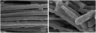
Fig. 5a shows that when the TiO2 HNAs was immersed in the AgNO3 (or HAuCl4) electrolyte solution, the surfaces of TiO2 HNAs were filled with metal ions. The surfaces of TiO2 HNAs were decorated with ultrafine Ag NPs after electrochemical deposition. The surface roughness seems to decrease upon loading with Ag (or Au) NPs, indicating that metal NPs may preferentially deposit in the gaps between aggregated TiO2 NPs. Compared to TiO2 HNAs, the lengths of Ag/TiO2 (or Au/TiO2) HNCAs are longer, and their continuity is better. Furthermore, other defects are also reduced.
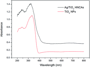
Fig. 6 shows the typical UV-Vis diffuse reflectance spectra of the prepared pure TiO2 NPs and Ag/TiO2 HNCAs. In this case, we observed that the pure TiO2 NPs have no ability to respond under visible light; however, the absorption of the Ag/TiO2 HNCAs extends significantly into both the ultraviolet and visible regions. It is clear that the incorporation of Ag results in a substantial red shift of the absorption of TiO2. According to the results, the observed absorption of the of Ag/TiO2 HNCAs in the visible-light range can be attributed to the surface plasmon resonance (SPR) absorption of Ag NPs excited by light irradiation over the sample and the restraint of the electron–hole pair recombination. Obviously, the boosted light absorption contributes to enhancing the photoelectronic efficiency and therefore the photocatalytic activity.
The XPS spectra of the Ag/TiO2 HNCAs present more evidence of Ag NP deposition. The results (Fig. 7a) clearly show three major sets of peaks corresponding to the O 1s, Ti 2p, and Ag 3d states in the Ag/TiO2 HNCA sample. No trace of any impurities was observed, except for a small amount of adventitious carbon from the XPS instrument itself. From Fig. 7b, it can be seen that the Ag 3d5/2 and Ag 3d3/2 spin–orbitals are located at binding energies of 367.7 and 373.8 eV, respectively. The 6.1 eV difference between the binding energies of the peaks is also characteristic of metallic Ag 3d states. This binding energy also indicates that Ag mainly exists in the Ag0 state on the surfaces of the TiO2 HNAs.
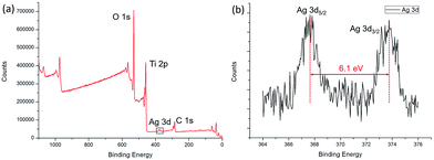 | ||
| Fig. 7 (a) XPS spectrum of the prepared Ag/TiO2 HNCAs and (b) high-resolution XPS spectrum of Ag 3d. | ||
3.2 Photocatalytic activities
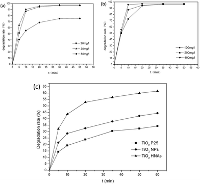
The optimum concentration of MO was determined by photocatalytic experiments. Certain amounts of aggregated TiO2 NPs were dispersed into 500 mL MO solutions with initial concentrations of 20, 30 and 50 mg L−1. As demonstrated in Fig. 8a, the photodegradation of MO (20 and 30 mg L−1) is almost finished within 20 min. By increasing the MO concentration to 50 mg L−1, the degradation rate was reduced to 75%. This can be ascribed to the fact that the photocatalytic reaction principally occurs on the surface of the photocatalyst. For the intermediate concentration of MO, a sufficient amount of ˙OH can be applied to promote the photocatalytic reaction in the region of the TiO2 NP surfaces. Furthermore, we investigated the influence of different dosages of aggregated TiO2 NPs on the photocatalytic activities. As displayed in Fig. 8b, 95% of MO can be degraded in the presence of TiO2 NPs after 20 min. However, we found that the performance obtained with 200 mg L−1 photocatalyst was better than that obtained with 100 mg L−1 and close to that obtained with 400 mg L−1 in the first 10 min. To evaluate the photocatalytic efficiency, we compare the degradation rate between TiO2 P25, aggregated TiO2 NPs and TiO2 HNAs based on the abovementioned results (Fig. 8c). Herein, the photocatalytic performance was studied under UV light illumination. The experimental results indicated that only a small fraction of MO is degraded when using TiO2 P25 and aggregated TiO2 NPs as the photocatalyst.Fig. 9 shows the photocatalytic degradation rates of MO on the metal/TiO2 HNCAs and TiO2 HNAs. The results show that the metal/TiO2 HNCAs exhibit higher photocatalytic activity than the TiO2 HNAs, implying that the metal/TiO2 HNCAs are expected to possess high photocatalytic activity and potential practical applications in the degradation of the organic contaminants in water.
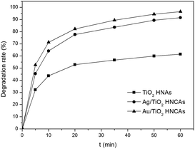 | ||
| Fig. 9 Photocatalytic degradation rate of MO in the presence of Au/TiO2 HNCAs, Ag/TiO2 HNCAs and TiO2 HNAs after illumination with a UV lamp (300 W). | ||
One of the major bottlenecks in TiO2-based photocatalysis is insufficient surface-active centres. Therefore, the synthesis of nanosized TiO2 with large surface area plays a vital role in further improving the photodegradation efficiency. Due to the different formation mechanism, the assembly process of TiO2 NPs on the AAO template is distinguished from those of other nanomaterials. In this work, aggregated TiO2 NPs deposited in the holes of the AAO template and then assembled as a uniform nanoarray structure. In fact, the lengths of the TiO2 HNAs can be controlled by controlling the deposition time.62–64 It should also be noted that the diameters of the TiO2 HNAs can be tuned by the pore size of the AAO template, which may be another critical aspect in the development of TiO2 HNAs.
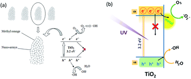
As illustrated in Scheme 3(a), the TiO2 HNAs are made from aggregated TiO2 NPs, which facilitate the adsorption of MO molecules on the surface of nanosized TiO2 as well as the diffusion of MO into the interior spaces of HNAs. The band gap of TiO2 between the valence band and the conduction band is 3.2 eV. Triggered by UV light illumination, the photogenerated electrons (e−) in the valence band transfer to the conduction band, leaving a photogenerated hole (h+) in the valence band. Dissolved oxygen (O2) adsorbed on the TiO2 surface can capture electrons (e−) from nanosized TiO2 and then produce superoxide anion free radicals (˙O2−), which possess strong oxidizing ability. Meanwhile, holes can react with OH− and H2O adsorbed on the TiO2 surface to form hydroxyl radical (˙OH).65–67 Due to the strong oxidizing ability of ˙OH and ˙O2−, no intermediate products in the oxidation reaction process are expected. Under continuous UV light illumination, the separated photogenerated electrons and holes in the valence and conduction bands can be employed to photodegrade MO and other organic dyes into CO2 and H2O.68–70
Scheme 3(b) demonstrates the photogenerated charge transfer process between TiO2 and metal NPs. Previous reports revealed that the modification of metal NPs on semiconductor surfaces can enhance the photocatalytic efficiency by effectively trapping the photogenerated electrons from metal NPs decorated on the TiO2 surfaces, or by charge-transfer resulting from the Fermi levels of these metal NPs lower than the conduction bands of the semiconductors.71–73 The deposition of metal NPs can be considered as an effective way to suppress electron–hole recombination. Consequently, more holes will be available for the photocatalytic reactions. The promotion is derived from the difference in the electronic work functions between the TiO2 and deposited metal NPs. Considering the minimum energy value of the conduction band of TiO2 is still higher than the Fermi energy level of the metal/TiO2 composite structure, photogenerated electrons will simultaneously transfer from the TiO2 to the decorated metal NPs until the equilibrium of the Fermi levels attained under external activation such as UV irradiation. Furthermore, the Schottky barriers formed between metal NPs and TiO2 can capture the electrons generated at the metal/TiO2 HNCA interfaces to prevent electron–hole recombination.74–76 The hole in the valence band has a strong oxidation ability, and most of the organic chemicals can be rapidly decomposed into CO2, H2O and other nontoxic substances after UV light illumination. On one hand, electrons have to be triggered to overcome the barrier from TiO2 to the metal NPs. On the other hand, electrons will be blocked by the barrier. For metal/TiO2 HNCAs, the abundant interfacial electrons and photogenerated holes react with O2 and H2O molecules under UV irradiation, enhancing the amounts of ˙O2− and ˙OH and improving the photocatalytic activities. Therefore, TiO2 HNAs can be considered as potential building blocks for chemical sensors and energy-harvesting devices due to their small dimensions, high material quality, large surface-to-volume ratio, etc.
4. Conclusions
Using aggregated anatase TiO2 NPs, we demonstrated a convenient and universal approach to fabricate uniform TiO2 HNAs with the assistance of an AAO template. Our experimental results revealed that TiO2 HNAs demonstrate remarkably enhanced photocatalytic activity for the removal of MO compared to aggregated TiO2 NPs due to its specific large-scale surface characteristics. Metals (Ag and Au) were deposited on the TiO2 HNA surfaces to form metal/TiO2 HNCAs. Compared to the TiO2 HNAs, the HNCAs exhibit extraordinary photocatalytic activity for the photodegradation of MO. In this work, we enriched the synthetic methodology for complex nanostructured TiO2 and provided a strategy to enhance the photocatalytic efficiency. The prepared materials show great potential for the degradation of organic pollutants in wastewaters.Acknowledgements
This work is financially supported by National Natural Science Foundation of China (NSFC no. 21471103, 51278026, 51678026, 21103008).Notes and references
- A. Fujishima and K. Honda, Nature, 1972, 238, 37 CrossRef CAS PubMed.
- X. Wang, Z. Li, J. Shi and Y. Yu, Chem. Rev., 2014, 114, 9346 CrossRef CAS PubMed.
- J. Schneider, M. Matsuoka, M. Takeuchi, J. Zhang, Y. Horiuchi, M. Anpo and D. W. Bahnemann, Chem. Rev., 2014, 114, 9919 CrossRef CAS PubMed.
- X. Chang, S. S. Thind, M. Tian, M. M. Hossain and A. Chen, Electrochim. Acta, 2015, 173, 728 CrossRef CAS.
- Y. Zhuang, F. Yu and J. Ma, J. Nanomater., 2015, 2015, 1 CrossRef.
- J. M. Ball, M. M. Lee, A. Hey and H. J. Snaith, Energy Environ. Sci., 2013, 6, 1739 CAS.
- Q. Chen, H. Zhou, Z. Hong, S. Luo, H. S. Duan, H. H. Wang, Y. Liu, G. Li and Y. Yang, J. Am. Chem. Soc., 2014, 136, 622–625 CrossRef CAS PubMed.
- N. J. Jeon, J. H. Noh, Y. C. Kim, W. S. Yang, S. Ryu and S. I. Seok, Nat. Mater., 2014, 13, 897–903 CrossRef CAS PubMed.
- D. Liu and T. L. Kelly, Nat. Photonics, 2013, 8, 133–138 CrossRef.
- M. Liu, M. B. Johnston and H. J. Snaith, Nature, 2013, 501, 395–398 CrossRef CAS PubMed.
- M. Ma, Q. Tang, P. Yang and B. He, RSC Adv., 2016, 6, 82933–82940 RSC.
- G. Cappelletti, C. L. Bianchi and S. Ardizzone, Appl. Catal., B, 2008, 78, 193 CrossRef CAS.
- J. M. Meichtry, M. Brusa, G. Mailhot, M. A. Grela and M. I. Litter, Appl. Catal., B, 2007, 71, 101 CrossRef CAS.
- K. Nagaveni, G. Sivalingam, M. S. Hegde and G. Madras, Appl. Catal., B, 2004, 48, 83 CrossRef CAS.
- C. E. Bonancêa, G. M. do Nascimento, M. L. de Souza, M. L. A. Temperini and P. Corio, Appl. Catal., B, 2006, 69, 34 CrossRef.
- D. Li, Y. Guo, C. Hu, C. Jiang and E. Wang, J. Mol. Catal. A: Chem., 2004, 207, 183 CrossRef CAS.
- M. Dahl, Y. Liu and Y. Yin, Chem. Rev., 2014, 114, 9853 CrossRef CAS PubMed.
- I. J. Puentes-Cárdenas, G. M. Chávez-Camarillo, C. M. Flores-Ortiz, M. D. C. Cristiani-Urbina, A. R. Netzahuatl-Muñoz, J. C. Salcedo-Reyes, A. M. Pedroza-Rodríguez and E. Cristiani-Urbina, J. Nanomater., 2016, 2016, 1 CrossRef.
- H. Wang, J. J. Miao, J. M. Zhu, H. M. Ma, J. J. Zhu and H. Y. Chen, Langmuir, 2004, 20, 11738 CrossRef CAS PubMed.
- P. Yang, T. Deng, D. Zhao, P. Feng, D. Pine, B. F. Chmelka, G. M. Whitesides and G. D. Stucky, Science, 1998, 282, 2244 CrossRef CAS PubMed.
- C. C. Wang, C. C. Kei, Y. W. Yu and T. P. Perng, Nano Lett., 2007, 7, 1566 CrossRef CAS PubMed.
- C. Z. Wang, Y. F. E, L. Z. Fan, Z. H. Wang, H. B. Liu, Y. L. Li, S. H. Yang and Y. L. Li, Adv. Mater., 2007, 19, 3677 CrossRef CAS.
- J. Q. Li, D. F. Wang, H. Liu, Z. L. He and Z. F. Zhu, Appl. Surf. Sci., 2011, 257, 5879 CrossRef CAS.
- J. Yu, Q. Xiang, J. Ran and S. Mann, CrystEngComm, 2010, 12, 872 RSC.
- Y. C. Liang, C. C. Wang, C. C. Kei, Y. C. Hsueh, W. H. Cho and T. P. Perng, J. Phys. Chem. C, 2011, 115, 9498 CAS.
- J. M. Macak, M. Zlamal, J. Krysa and P. Schmuki, Small, 2007, 3, 300 CrossRef CAS PubMed.
- Y. S. Sohn, Y. R. Smith, M. Misra and V. Subramanian, Appl. Catal., B, 2008, 84, 372 CrossRef CAS.
- L. L. Costa and A. G. S. Prado, J. Photochem. Photobiol., A, 2009, 201, 45 CrossRef CAS.
- M. J. Zheng, L. D. Zhang, G. H. Li and W. Z. Shen, Chem. Phys. Lett., 2002, 363, 123–128 CrossRef CAS.
- X. Zhang, F. Shi, X. Yu, H. Liu, Y. Fu, Z. Wang, L. Jiang and X. Li, J. Am. Chem. Soc., 2004, 126, 3064–3065 CrossRef CAS PubMed.
- C. L. Yu, Y. Bai, J. C. Chen, W. Q. Zhou, H. B. He, J. C. Yu, L. H. Zhu and S. S. Xue, Sep. Purif. Technol., 2015, 154, 115–122 CrossRef CAS.
- S. M. Li, Y. S. Wang, S. Y. Yang, C. H. Liu, K. H. Chang, H. W. Tien, N. T. Wen, C. C. M. Ma and C. C. Hu, J. Power Sources, 2013, 225, 347–355 CrossRef CAS.
- N. Eliaz, T. M. Sridhar, U. Kamachi Mudali and B. Raj, Surf. Eng., 2013, 21, 238–242 CrossRef.
- F. Pishbin, V. Mourino, J. B. Gilchrist, D. W. McComb, S. Kreppel, V. Salih, M. P. Ryan and A. R. Boccaccini, Acta Biomater., 2013, 9, 7469–7479 CrossRef CAS PubMed.
- C. L. Yu, W. Q. Zhou, H. Liu, Y. Liu and D. D. Dionysiou, Chem. Eng. J., 2016, 287, 117–129 CrossRef CAS.
- A. Santibañez, M. Herrera-Trejo, J. Oliva and A. I. Martinez, Superlattices Microstruct., 2016, 100, 973–982 CrossRef.
- K. Nagaveni, G. Sivalingam, M. S. Hegde and G. Madras, Environ. Sci. Technol., 2004, 38, 1600 CrossRef CAS PubMed.
- A. Kumar, L. Rout, L. S. K. Achary, A. Mohanty, R. S. Dhaka and P. Dash, RSC Adv., 2016, 6, 32074 RSC.
- B. A. Aragaw, C. J. Pan, W. N. Su, H. M. Chen, J. Rick and B. J. Hwang, Appl. Catal., B, 2015, 163, 478 CrossRef CAS.
- M. Liu, K. L. Lv, G. H. Wang, Z. Y. Wang, Y. X. Zhao and Y. R. Deng, Chem. Eng. Technol., 2010, 33, 1531 CrossRef CAS.
- M. Landmann, E. Rauls and W. G. Schmidt, J. Phys.: Condens. Matter, 2012, 24, 195503 CrossRef CAS PubMed.
- M. Lahav, T. Sehayek, A. Vaskevich and I. Rubinstein, Angew. Chem., Int. Ed. Engl., 2003, 42, 5575 CrossRef PubMed.
- J. Chen, L. Eberlein and C. H. Langford, J. Photochem. Photobiol., A, 2002, 148, 183 CrossRef CAS.
- M. R. Hoffmann, S. T. Martin, W. Choi and D. W. Bahnemann, Chem. Rev., 1995, 95, 69 CrossRef CAS.
- J. C. D'Oliveira, C. Minero, E. Pelizzetti and P. Pichat, J. Photochem. Photobiol., A, 1993, 72, 261 CrossRef.
- D. Z. Lu, H. M. Wang, X. N. Zhao, K. K. Kondamareddy, J. Q. Ding, C. H. Li and P. F. Fang, ACS Sustainable Chem. Eng., 2017, 5, 1436 CrossRef CAS.
- L. J. Li, J. Zhang, J. L. Lei, J. Xu, P. P. Liu, N. B. Li and F. S. Pan, RSC Adv., 2016, 6, 34507 RSC.
- D. S. Bhatkhande, V. G. Pangarkar and A. A. Beenackers, J. Chem. Technol. Biotechnol., 2001, 77, 102 CrossRef.
- G. Sivalingam, K. Nagaveni, M. S. Hegde and G. Madras, Appl. Catal., B, 2003, 45, 23–38 CrossRef CAS.
- C. L. Yu, K. Yang, Y. Xie, Q. Z. Fan, J. C. Yu, Q. Shua and C. Y. Wang, Nanoscale, 2013, 5, 2142–2151 RSC.
- G. Sivalingam, M. H. Priya and G. Madras, Appl. Catal., B, 2004, 51, 67 CrossRef CAS.
- S. Liu, J. Yu and M. Jaroniec, J. Am. Chem. Soc., 2010, 132, 11914 CrossRef CAS PubMed.
- X. Xu, X. Fang, T. Zhai, H. Zeng, B. Liu, X. Hu, Y. Bando and D. Golberg, Small, 2011, 7, 445 CrossRef CAS PubMed.
- S. T. Ong, C. K. Lee, Z. Zainal, P. S. Keng and S. T. Ha, J. Fundam. Appl. Sci., 2009, 5, 88 Search PubMed.
- L. A. Díaz, W. Solís, P. Peretyagin, A. Fernández, M. Morales, C. Pecharromán, J. S. Moya and R. Torrecillas, J. Nanomater., 2016, 2016, 1 CrossRef.
- Y. W. Lin, C. W. Lu, G. P. Yu and J. H. Huang, J. Nanomater., 2016, 2016, 1 Search PubMed.
- J. Liao, S. Lin, L. Zhang, N. Pan, X. Cao and J. Li, ACS Appl. Mater. Interfaces, 2012, 4, 171 CAS.
- Y. Tang, P. Wee, Y. Lai, X. Wang, D. Gong, P. D. Kanhere, T.-T. Lim, Z. Dong and Z. Chen, J. Phys. Chem. C, 2012, 116, 2772 CAS.
- Y. Kim, H. Joo, N. Her, Y. Yoon, C. H. Lee and J. Yoon, Chem. Eng. J., 2013, 229, 66 CrossRef CAS.
- C. L. Yu, F. F. Cao, X. Li, G. Li, Y. Xie, J. C. Yu, Q. Shu, Q. Z. Fan and J. C. Chen, Chem. Eng. J., 2013, 219, 86–95 CrossRef CAS.
- T. D. Pham, B. K. Lee and D. Pham Cong, RSC Adv., 2016, 6, 25346 RSC.
- H. Hossaini, G. Moussavi and M. Farrokhi, Water Res., 2014, 59, 130 CrossRef CAS PubMed.
- G. Liu, L. Wang, H. G. Yang, H. M. Cheng and G. Q. Lu, J. Mater. Chem., 2010, 20, 831 RSC.
- W. P. Zhang, X. Y. Xiao, Y. Li, X. Y. Zeng, L. Zheng and C. Wan, RSC Adv., 2016, 6, 33705 RSC.
- S. Maiti, U. N. Maiti and K. K. Chattopadhyay, Synth. React. Inorg. Met.-Org. Chem., 2014, 44, 1255 CrossRef CAS.
- V. Subramanian, E. E. Wolf and P. V. Kamat, J. Am. Chem. Soc., 2004, 126, 4943 CrossRef CAS PubMed.
- L. L. Lai, W. Wen and J. M. Wu, RSC Adv., 2016, 6, 25511 RSC.
- M. Amin, J. Tomko, J. J. Naddeo, R. Jimenez, D. M. Bubb, M. Sitener, J. Fitz-Gerald and S. M. O'Malley, Appl. Surf. Sci., 2015, 348, 30 CrossRef CAS.
- C. L. Yu, W. Q. Zhou, L. H. Zhu, G. Li, K. Yang and R. C. Jin, Appl. Catal., B, 2016, 184, 1–11 CrossRef CAS.
- X. Zhang, Y. Zhang, D. Liu, J. Feng, L. Zhou, Y. Yang, X. Guo and X. Li, RSC Adv., 2016, 6, 34650 RSC.
- S. Banerjee, S. K. Mohapatra, P. P. Das and M. Misra, Chem. Mater., 2008, 20, 6784 CrossRef CAS.
- M. Jakob, H. Levanon and P. V. Kamat, Nano Lett., 2003, 3, 353 CrossRef CAS.
- C. Liu, R. F. Tong, Z. K. Xu, Q. Kuang, Z. Xie and L. Zheng, RSC Adv., 2016, 6, 29794 RSC.
- X. He, Y. Cai, H. Zhang and C. Liang, J. Mater. Chem., 2011, 21, 475 RSC.
- A. L. Linsebigler, G. Lu and J. T. Yates, Chem. Rev., 1995, 95, 735 CrossRef CAS.
- A. Wold, Chem. Mater., 1993, 5, 280 CrossRef CAS.
| This journal is © The Royal Society of Chemistry 2017 |

