 Open Access Article
Creative Commons Attribution 3.0 Unported Licence
Headway in rhodanide anion based ternary gel polymer electrolytes (TILGPEs) for applications in rechargeable lithium ion batteries: an efficient route to achieve high electrochemical and cycling performances†
K. Karuppasamy *ab,
K. Prasannac,
Dongkyu Kima,
Yong Hee Kanga and
Hee Woo Rhee*a
aPolymer Materials Lab, Department of Chemical and Biomolecular Engineering, Sogang University, 35 Baekbeom-ro, Mapo-Gu, Seoul 04107, South Korea. E-mail: karuppasamyiitb@gmail.com; hwrhee@sogang.ac.kr
bDivision of Electronics and Electrical Engineering, Dongguk University-Seoul, Seoul 04620, South Korea
cElectrochemical Energy Storage and Conversion Lab (EESC), Kyung Hee University, 1732, Deogyeong-daero, Giheung-gu, Yongin, Gyeonggi 17104, South Korea
First published on 31st March 2017
Abstract
In this present investigation, we developed a new category of rhodanide anion based ternary gel polymer electrolytes (TILGPEs) with high electrochemical and thermal stability, which advantageously use the harmonizing properties of a temperature-responsive polymer poly vinylidene fluoride-co-hexafluoropropylene (PVdF-co-HFP) and room temperature ionic liquid (1-ethyl-3-methylimiazolium rhodanide (thiocyanate), (EMImSCN)). TILGPEs were fabricated using a facile solution cast method by incorporating EMImSCN and lithium rhodanide (LiSCN) into PVdF-co-HFP based membranes. Among the series of electrochemical tests including electrochemical impedance spectroscopy, cyclic voltammetry, linear sweep voltammetry and chronoamperometry, the membrane with 80 wt% electrolyte mixtures (EMImSCN/LiSCN) showed better performance in all aspects. The maximum ionic conductivity was found to be in the order of 2.8 × 10⁻⁴ S cm−1 at 298 K. The LiFePO4/TILGPE3/Li cell offered a maximum discharge capacity of 149.8 mA h g−1 at C/10 rate. The inimitable properties allowed the effective use of the rhodanide TILGPEs as active separators for the development of advanced lithium ion batteries.
1. Introduction
During the past three decades, rechargeable lithium ion batteries have received great consideration as the most plausible next generation of power sources for electric vehicles and portable electronic devices due to their relatively high specific energy storage capabilities.1–4 Nevertheless the utilization of flammable liquid electrolytes in rechargeable secondary batteries upsurges the safety concerns.5 Therefore, substituting flammable electrolytes and enhancing the energy density of batteries are at the forefront of research in both academia and industry. Gel polymer electrolytes (GPEs) have been intensively studied as an alternative to their liquid counterparts. The foremost benefits of GPEs in lithium ion batteries (LIBs) lies with their high ionic conductivity and non-leakage nature, as compared to those spotted for liquid electrolytes, and their capacity to construct electrolytes as flexible thin films leading to greater energy density in batteries.6–8 Utmost of the reported GPEs are consisted of liquid electrolyte solution of salts in volatile organic carbonate solvents such as ethylene carbonate (EC), diethyl carbonate (DEC), propylene carbonate (PC) and so forth immobilizing in polymer host matrix. But when considering organic solvents for GPEs preparation, the major drawbacks that we generally come across is their meager thermal and electrochemical properties with organic solvents that are volatile in nature, and their relatively narrow electrochemical potential window.7,8In order to overcome the above said issues, scientists and researchers have employed various types of additives to enhance electrochemical and cycling stability greater to most organic solvents. Among them, room temperature ionic liquids (ILs) are a very promising class of candidate for the fabrication of GPEs which would allow for the construction of batteries with reduced fire hazards due to its negligible vapor pressure and low flammability.9–12 It also functions as solvent to plasticize ion-coordinating polymers and to dissolve lithium salts, promoting fast ions migration.13 Also in the past, numerous polymers were investigated as hosts for GPEs system including PVdF-co-HFP, PEO, PMMA, PAN and so forth.14–18 Between them, PVdF-co-HFP is considered to be the best because of high electrochemical stability and its ability to dissolve lithium salts due to its high dielectric constant (ε = 11.38) in amorphous phase.19–22
Past one decade, prodigious deals of efforts have been devoted to improve the ionic conductivity and performance of gel electrolytes for LIBs. Quite a lot of anions based electrolyte mixtures such as TFSI−, CF3SO3−, BF4−, nonaflate are successfully used as gel polymer electrolytes in lithium-ion battery.23–28 Among them, rhodanide anion (familiarly known as thiocyanate SCN−) is believed to be most promising anion for electrolyte preparation because it has a strong electron withdrawing group, possesses a lower LUMO (Low Unoccupied Molecular Orbital) and a higher electrochemical stability for wide electrochemical window towards batteries with high energy.29,30 In the present study, we report a new class of ternary gel polymer electrolyte (TILGPEs) membranes prepared by encompassing rhodanide anion based lithium salt and ionic liquid [1-ethyl-3-methylimidazolium rhodanide (EMImSCN)] into a PVdF-co-HFP matrix. Lithium rhodanide is of quite interest due to the fact that it is thermally stable at elevated temperatures, insensitive to ambient moisture, eco-friendly (non-toxic) as compared to other conventional lithium salts.31,32 A synergistic effect of electrolyte mixture (LiSCN/EMImSCN) on the electrochemical and cycling performance of TILGPEs has been observed and will be discussed in this work and also, there were no previous report on LiSCN/EMImSCN as active materials for electrolytes in LIB applications. The detailed investigations on electrochemical behavior of TILGPEs have been characterized using impedance analysis (EIS), cyclic voltammetry, chronoamperometry and charge discharge analysis and the significant results are presented herein.
2. Experimental
2.1. Materials
Poly(vinylidinefluoride-co-hexafluoropropyline) (PVdF-co-HFP pellets, average molecular weight, Mw 4 × 10⁵), 1-ethyl-3-methyl imidazolium thiocyanate (EMImSCN, ≥99.1% pure, H2O-impurities: <0.12% (Karl-Fischer titration) and Mw 169.25) and lithium rhodanide (LiSCN, anhydrous basis, Mw 65.02) were purchased from Aldrich. The lithium salt and ionic liquid were kept under vacuum at 70 °C for 12 h prior to use. In the whole preparation process, anhydrous acetonitrile (Aldrich) was used as solvent.2.2. Preparation of ternary gel polymer electrolytes (TILGPEs)
The electrolyte mixture LiSCN/EMImSCN was prepared by dissolving 0.3 M of LiSCN in the neat ionic liquid EMImSCN and it was subjected to constant magnetic stirring at 60 °C until homogeneous solution was obtained. The gel polymer electrolyte films were prepared using facile solution cast technique.28 In this method, the mixtures of LiSCN/EMImSCN and PVdF-co-HFP were prepared in different ratios as shown in Table 1. Initially, the polymer host PVdF-co-HFP was dissolved in anhydrous acetonitrile separately. After that, various weight ratios of electrolyte mixture and PVdF-co-HFP solution were then mixed using a magnetic stirrer in a one necked flask at 60 °C for 12 h. The obtained pasty mass solution was transferred into Teflon Petri dishes and then dried under vacuum for 24 h. The resulting dimensionally free standing TILGPEs having a thickness of 150–180 μm (as shown in Fig. S1 of ESI†) was stored in an inert atmosphere for further characterizations.| TILGPEs | Ea (eV) | σ at 398 K (S cm−1) | Anodic stability (V) | Tg (°C) | Tm (°C) | Crystallinity % α | Thermal stability (°C) |
|---|---|---|---|---|---|---|---|
| a TILGPE1 (60% LiSCN/IL + 40% PVdF–HFP), TILGPE2 (70% LiSCN/IL + 30% PVdF–HFP) and TILGPE3 (80% LiSCN/IL + 20% PVdF–HFP). | |||||||
| TILGPE1 | 0.283 | 3.5 × 10⁻⁴ | 3.40 | −32.23 | 139.63 | 46.31 | 251 |
| TILGPE2 | 0.178 | 3.3 × 10⁻³ | 3.50 | −30.64 | 130.61 | 43.42 | 252 |
| TILGPE3 | 0.026 | 2.8 × 10⁻² | 3.60 | −27.81 | 115.41 | 41.80 | 256 |
2.3. Materials characterizations
The X-ray diffraction analysis of prepared gel electrolytes were carried out using an X-ray diffractometer (D-MAX 2500, Rigaku) with Cu-Kα radiation (λ = 1.5406 Å) generated at 40 kV and 30 mA flux in the 2θ range between 0 and 100° at ambient temperature. The differential scanning calorimetry (DSC) measurement of pure polymer host and TILGPEs were made on TA Instruments, (Model 2920) thermal analyzer at a heating rate of 10 °C min−1 under nitrogen atmosphere in the temperature range of −50 to 200 °C. The thermogravimetry (TGA) analysis of TILGPEs was carried out on a TGA-2950 thermal analyzer (Hi-Res, TA instruments) by heating from 25 to 700 °C under a N2 atmosphere at a heating rate of 20 °C min−1. FTIR spectra were recorded with the help of a Nicolet 380 FT-IR spectrometer (Thermo Electron) in the region 4000–400 cm−1 at a signal resolution of 1 cm−1.The ionic conductivities of the prepared TILGPEs were analyzed by electrochemical impedance spectroscopy (EIS). The electrolyte samples analysis was performed in blocking type cells where the TILGPEs were sandwiched between two stainless steel electrodes. The ionic conductivity of the TILGPEs having an area of 1.7665 cm2 were measured using ac-impedance spectroscopy (Ivium Technologies, Netherlands) in the frequency range (1–106) Hz with amplitude signal of 10 mV. The temperature dependence of ionic conductivity was performed in the temperature range between 298 and 398 K. The ionic conductivity was evaluated from the intercept of the low frequency spike with the real axis obtained from impedance measurements.32 The ionic conductivity of TILGPEs was calculated from eqn 1
| σ = t/RbA | (1) |
The total lithium transference number (tLi+) of prepared TILGPEs was measured using AC impedance and DC polarization method. A step voltage of 20 mV was applied across the symmetrical Li/TILGPE3/Li cell and the resulting current was measured as a function of time (chronoamperometry) at 333 K.32 The lithium transference number (tLi+) of TILGPE was obtained by eqn (2)
 | (2) |
The linear sweep voltammetry and cyclic voltammetry analyses of TILGPEs were examined using Li/TILGPEs/Li symmetric cell at 298 K. These analyses were carried out using Ivium Technologies electrochemical workstation. For LSV, the potential range fixed from 0 to 5 V at a scan rate of 20 mV s−1. CV analysis was performed at different scan rates in the potential limit between −5 and +5 V. The cycling performance of TILGPE3 was observed in galvanostatic mode using BT2000 Arbin cycler. Charge–discharge analysis was carried out for the 2032 coin cell assembled by sandwiching the TILGPE3 between the commercially available LiFePO4 cathode foil (MTI corporations) and lithium metal anode. The coin cell was cycled between the cut-off voltage of 2.7 and 4.1 V at five different C-rates at room temperature.
3. Results and discussions
3.1. Crystalline behavior of ternary gel polymer electrolytes
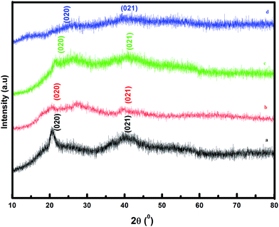
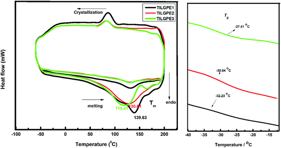
The XRD patterns of pure PVdF-co-HFP, TILGPE-1, TILGPE-2 and TILGPE-3 respectively are shown in Fig. 1. The peaks observed at 2θ = 20.38, 39.12 and 41.26 (corresponds to (1 0 0), (0 2 0) and (0 2 1) reflection planes respectively) reveal the partial crystallization of PVdF units present in the complexes, giving an overall semi crystalline morphology of PVdF-co-HFP.33,34 The XRD patterns of TILGPEs show decrease of intensity of the semi-crystalline peak of pure PVdF-co-HFP with the addition of electrolyte mixture content. This is due to the enhanced amorphicity of the prepared membranes. Furthermore, no peaks are found for electrolyte mixture (LiSCN/EMImSCN) reveals the completely dissolution of electrolyte mixture in the polymer matrix. This result is similar to the result obtained by Qingqing Zhang et al.35 The lowest intensity is achieved with incorporation of 80 wt% of rhodanide electrolyte mixture. Subsequently, the variation of intensity in gel polymer electrolytes after the addition of rhodanide electrolyte mixture can be expected as the evidence of complexation between PVdF-co-HFP polymer and rhodanide electrolyte mixture. The results suggest that adding electrolyte mixture into PVdF-co-HFP can reduce the crystallinity and increase the amorphous areas of polymer matrix thereby enhances ionic conductivity of the TILGPEs. In other words, the broadening of peak in the diffractogram is a clear evidence for amorphous nature (due to polymer segmental motion enhancement) which is responsible for ionic conductivity of TILGPEs which will be discussed later in the following sections.DSC analysis is performed to validate the XRD results as well as to evaluate change in crystallinity in gel polymer matrix in the temperature range between −50 and 200 °C. The DSC thermogram of pristine PVdF-co-HFP and electrolyte mixture (EMImSCN/LiSCN) in the temperature range are shown in Fig. S2 (see ESI†). It is observed from the thermogram that the pristine PVdF-co-HFP and electrolyte mixture shows a sharp melting endotherm (Tm) at 142 °C and 125 °C respectively. The glass transition temperature (Tg) of PVF-co-HFP appears around −35 °C. Fig. 2 represents the DSC thermogram of different ternary gel electrolytes namely TILGPE1, TILGPE2 and TILGPE3 in the temperature range between −50 °C and 200 °C. As shown in figure the Tm, Tg and % α (degree of crystallinity) of the prepared TILGPEs move towards lower temperature side upon the addition of different weight percent of electrolyte mixture in the polymer which is due to the plasticization effect of electrolyte mixture. The presence of electrolyte mixture in PVdF-co-HFP matrix weakened the interactive bonds between the chains within the gel electrolytes which in turn reduces the amount of energy consumed to break the bond.36,37 Among the prepared TILGPEs, the gel electrolyte with 80% electrolyte mixture shows a low value of melting temperature (Tm). i.e., it is clearly seen from Fig. 2(a) that the melting temperature (Tm) of pure host decreases from 142 to 115.41 °C which is usually detected in various PVdF-co-HFP based systems.38,39 Similarly the value of Tg and α also reduces further in the presence of electrolyte mixture as shown in Fig. 2(b). The inclusion of LiSCN/EMImSCN in polymer matrix not only elevates the Tg of TILGPEs (∼−35 °C) but also broadens the Tg zone. This is due to the fact that the flexibility of polymer chains in the immediate vicinity of the ion–polymer complex site may behave differently from that in the bulk polymer matrix network.40 Its resultant values are summarized in Table 1.8 The degree of crystallinity (% α) of the prepared TILGPEs are estimated from the ratio of the area under melting peak (which is a measure of melting heat (ΔHm) involved in the phase transition) to the melting heat ΔHm 100% of 100% crystalline PVdF-co-HFP as per equation,
| % α = ΔHm/ΔHm 100% × 100 | (3) |
The value of ΔHm 100% is heat of fusion of 100% crystalline PVF-co-HFP which is taken as 104.5 J g−1.8 As it is evident from the table that the value of % α decreases with increase in electrolyte mixture content which indicates the increase in flexibility and mobility of the polymer chain segment in PVdF-co-HFP. As a result, the amorphous fraction in TILGPEs increases gradually thereby leads to increase the ionic conductivity which will be discussed later.
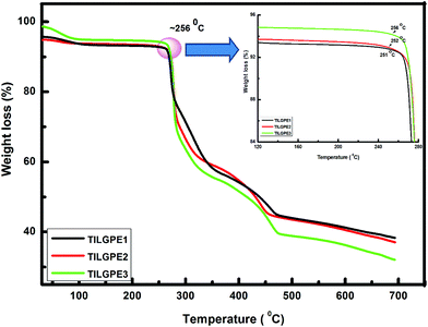
The thermal stability of the prepared ternary gel electrolytes was examined by thermogravimetric analysis (TGA) in the temperature range between 30 and 700 °C. The thermogram of pristine PVdF-co-HFP and electrolyte mixture LiSCN/EMImSCN are shown in Fig. S3 (see ESI†). For pure PVdF-co-HFP, there is no initial weight loss upto 406 °C whereas in the case of electrolyte mixture, the initial weight loss of 3–4% before 100 °C may due to absorption of moisture or water molecules during loading of sample. Moreover the electrolyte mixture is thermally stable up to 190 °C. Fig. 3 shows the TGA data for various ternary gel polymer electrolytes. On blending PVdF-co-HFP with different weight percentages of electrolyte mixture enhances the thermal stability of the gel electrolyte considerably. The TGA plots of all the TILGPEs show that steepest decomposition starts at a temperature higher than 250 °C. As can be seen, the TILGPEs shows a significant weight loss of 4% before 100 °C due to absorption of moisture and this little weight loss below 256 °C indicating a wide operating temperature range, which is important for many practical applications. Above 256 °C, there was a significant weight loss, which is attributed to the rupture of the electrolyte mixture from PVdF-co-HFP. The steepest weight loss was observed after 256 °C, which is attributed to both the degradation of the polymer backbone VdF and HFP.41 It is quite observed from the thermogram that the thermal stability of TILGPE3 is slightly higher than other two electrolytes. Such dissimilarity in thermal stability is attributed to the increase in content of electrolyte mixture in polymer matrix which is in concurrent with earlier reported result.26 Also, the temperature at around 256 °C for initiating thermal decomposition of TILGPEs is higher than the reported thermal stability of other imidazolium based ionic liquids complexed with PVdF-co-HFP.38
3.2. Confirmation of ion-polymer interactions in TILGPEs
In the present work, FT-IR analysis has been performed to investigate the ions and ionic liquid interaction within the PVdF-co-HFP host matrix. Fig. 4 depicts the FT-IR spectra of pure polymer host and different types of TILGPEs. As can be seen that the peaks appear at 1120 cm−1 and 1040 cm−1 belongs to asymmetrical stretch of CF2 group and bending of CF3 group of pure PVdF-co-HFP.42–44 Whereas FT-IR spectrum of electrolyte mixture (EMImSCN/LiSCN) shows characteristic peaks at 2600–2900, 2116, 1640 and 935 cm−1 corresponds to symmetrical CH2 stretching, asymmetrical C–N stretching (νa(C–N)), νa(CN) and symmetric SCN bending respectively32,45 (see ESI Fig. S4†). The inclusion of electrolyte mixture in to PVdF-co-HFP matrix preferably interacts with the free electron pairs of fluorine atom (CF2 and CF3 group) of host matrix which is evidenced by decrease in intensity of the vibrational peaks as represented in Fig. 4. Hence, to show the coordination between Li+ and EMIm+ ions with PVdF-co-HFP, the νa(CF2) and δ(CF3) vibrational modes will be examined for shift in wavenumbers towards right, which is an indicator for occurrence of cations (Li+ and EMIm+) interaction with the polymer host. Also the inclusion of electrolyte mixture in the PVdF-co-HFP matrix is further confirmed by the gradual enhancement of vibrational bands in the regions 2120 cm−1 (belongs to S–CN) and 910–930 cm−1 (δ(SCN)) which were quite absent in the case of pristine PVdF-co-HFP as displayed in Fig. 5(a). Its (δ(SCN)) corresponding deconvolution spectra are shown in Fig. 5(b). From figure, it can be seen that among the gel electrolytes, TILGE3 electrolyte shows an increase in intensity of SCN characteristic bands. The intensity of the five bands of TILGEs keeps increasing with increasing content of electrolyte mixture thereby confirm the presence of both anions and cations of electrolyte mixture in PVdF-co-HFP matrix. The results obtained are in concurrent with the result reported earlier by Arof et al.46,47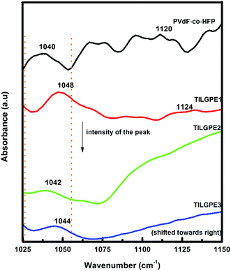 | ||
| Fig. 4 FT-IR spectrum of PVdF-co-HFP, TILGPE1, TILGPE2 and TILGPE3 in the wavenumber region 1025–1150 cm−1 (CF2 and CF3 stretching). | ||
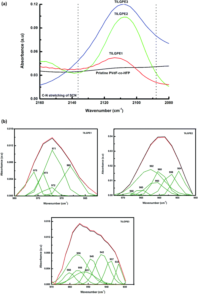 | ||
| Fig. 5 (a) C–N stretching of SCN in the wavenumber region 2160–2080 (b) Deconvoluted spectra of TILGPE1, TILGPE2 and TILGPE3. | ||
Fig. 6 shows the FTIR spectrum in two different regions namely 3000–2800 cm−1 and 980–840 cm−1 of pristine PVdF-co-HFP and TILGPEs containing different weight percentage of electrolyte mixture. These two regions are of our particular attentiveness because we have observed some crucial changes in the peak positions. It is observed from the Fig. 6 that almost all the intense vibrational peaks (2940 and 940 ∼ νas CH2 and δas(CF3)) belonging to pure polymer host start disappearing and or become weak. While, the characteristic vibrational peaks such as 2970, 2910, 2842, 950, 904 cm−1 of rhodanide electrolyte mixture become prominent as the concentration of electrolyte mixture increases in the polymer host matrix which indicates that electrolyte mixture increases the amorphicity of the polymer gel electrolytes.26 The obtained result strongly supports the result that we have found from XRD and DSC studies as discussed earlier.
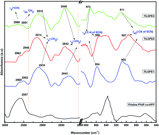 | ||
| Fig. 6 FT-IR spectrum of PVF-co-HFP, TILGPE1, TILGPE2 and TILGPE3 in the region between 3000 and 2800 cm−1 & 1000–840 cm−1. | ||
3.3. Ionic conductivity of TILGPEs
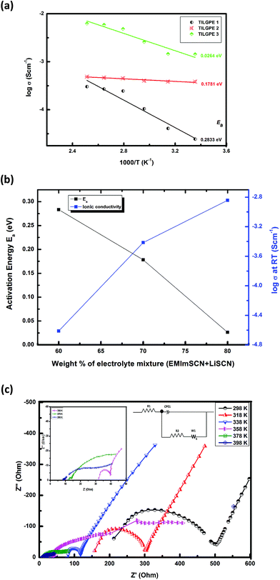
High ionic conductivity and wide potential electrochemical window are crucial requirement for electrolytes proposed to use for battery applications.8,14,48–50 In the present investigation, in order to validate the prospective for TILGPEs to be used as gel electrolyte in lithium ion battery and to determine the effect of electrolyte mixture on phase behavior, ionic conductivity measurement were performed for TILGPEs in the dry room at different temperatures. The temperature dependence of ionic conductivity for various TILGPEs in the temperature range between 298 and 398 K are depicted in Fig. 7(a). From the figure, it seems that it obeys Vogel–Taumann–Fulcher (VTF) relation49 as follows| σ = σ0e−Ea/R(T − T0) | (4) |
| σ = σ0e−Ea/RT | (5) |
It is observed from the Fig. 7(a) that the conductivity increases with increase in electrolyte mixture content in a linear fashion which is due to increased number of charge carriers in the host matrix. At 298 K, the conductivity values of TILGPE1, TILGPE2 and TILGPE3 are 2.4 × 10⁻⁵, 3.8 × 10⁻⁴ and 2.8 × 10⁻⁴ S cm−1 respectively. In addition for high temperature, the conductivity values increases phenomenonly for TILGPE1, TILGPE2 and TILGPE3 ranged from 3.5 × 10⁻⁴, 3.3 × 10⁻³ and 2.1 × 10⁻² S cm−1 respectively. As is common for typical gel electrolytes, the conductivity values enhances with increasing temperature. This indicates that the polymer chain segmental motion enhances and charge carriers are activated thermally at high temperature thereby favours the migration of lithium ions more faster in the polymer host matrix.51 Therefore, the ionic conductivity values of TILGPEs are found to be stable over the whole temperature range. Its corresponding values of σ and Ea for various TILGPEs are summarized in Table 1. As shown in Fig. 7(b), the value of Ea reduces gradually with increase in electrolyte mixture content which may due to the enhancement of flexibility of polymer chain thereby increases the amorphous nature and charge carriers in polymer host matrix.52 This result firmly strengthens the results obtained by XRD and DSC analyses as discussed earlier.
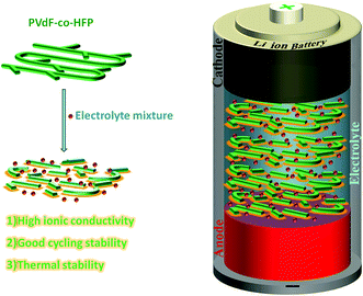
Further, it is also noticed that among the prepared electrolytes, TILGPE3 possess better conducting property compared to other two electrolytes. Its corresponding Nyquist plot with equivalent circuit is shown in Fig. 7(c). TILGPE3 provides ionic conductivities of the order of 10−4 S cm−1 at room temperature and achieved a maximum of 10−2 S cm−1 at 398 K respectively and it is found to be suitable in entire temperatures range. The results entail that the ionic conductivities of the TILGPE3 from 298 to 398 are all quite higher than that of other PVdF-co-HFP based gel electrolyte system.28 These obtained results of TILGPEs show an outstanding potential as a substitute for liquid electrolytes in electrochemical devices with wide range of operating temperatures. The salient features of prepared TILGPE3 is schematically represented in Scheme 1.
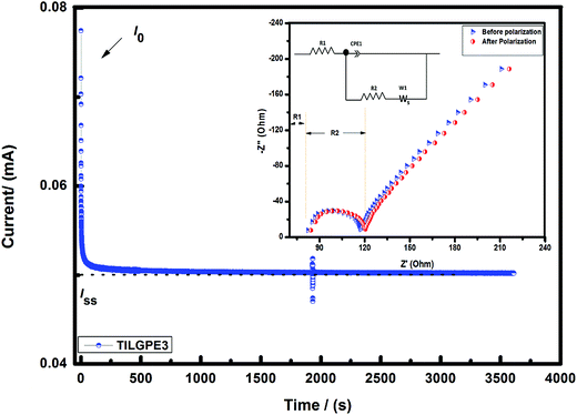
So as to improve the performance of the gel electrolytes especially rate and interfacial performance and to understand the migration of lithium ions in the gel matrix, the symmetric cell Li/TILGPE3/Li was subjected to chronoamperometry analysis at 333 K. The reason for choosing electrolyte TILGPE3 is that it yields high ionic conductivity at ambient and high temperatures compared to other two electrolytes. The tLi+ of TILGPE3 has been measured by a combining AC impedance and DC polarization method as proposed by Evans et al.53–55 Fig. 8 shows the variation of current as a function of time for TILGPE3 at a voltage of 20 mV. The value of tLi+ for TILGE3 is found to be 0.32 at 70 °C, which is quite comparable to that of other PVdF-co-HFP based systems reported in literature earlier.50 The tLi+ obtained in the present work is explained by means of a facile mechanism as follows: the Lewis acid sites of electrolyte mixture namely Li+ and EMIm+ can interact with the electron donor site CF2 of PVdF-co-HFP, SCN− and hence weakened the polymer backbone chain thereby increasing the amorphocity of gel electrolyte which in turn increase the electrical properties. Also, the result thus obtained is well matched with our conductivity results indicating that the increase in charge carriers in gel matrix play a key role in the ionic conductivity increment. Therefore, to conclude that the electrolyte mixture LiSCN/EMImSCN are incorporated to such network of the PVdF-co-HFP system, the overall conductivity of the system is high with appropriate transference number. Henceforth, the gel electrolyte TILGPE3 ought be a potential aspirant as separator for rechargeable lithium ion batteries. The observed findings are in concurrent with earlier reporter results by Yusong Zhu et al.18 The following sections will describe a profound idea about electrochemical and cycling stability of high conducting TILGPE3 and the details are presented below.
3.4. Electrochemical stability of TILGPEs
Electrochemical stability plays a key role to determine the potential application of polymer electrolytes for battery applications. In the present work, we have checked the electrochemical stability window (ESW) of the prepared electrolytes using linear sweep voltammetry analysis in the potential range between 0 and +5 V at 298 K which is the indicator to determine the working voltage range above which the prepared TILGPEs electrolytes remain safe and stable. With that intention, LSV analysis of the TILGPEs was performed by subjecting the symmetrical cell to LSV by means of sandwiching the TILGPE3 electrolyte between lithium electrodes (Li/TILGPE3/Li) and its corresponding results are plotted in Fig. 9(a). In the case of TILGPE1, the anodic stability is around 3.40 V. When the concentration of electrolyte mixture increases from 60 to 80%, the anodic stability limit is further lengthened into 3.60 V, however the catholic current is observed around 2.35 V (given in inset figure and marked as dotted circle in the main figure). Concerning the lithium anode and LiFePO4 cathode, it shows charge discharging profile plateau in the range between 2.4 and 3.8 V which exactly lies in the TILGPEs electrochemical potential range thereby demonstrates that the prepared TILGPEs are suitable for lithium anode and LiFePO4 cathode leading to battery applications. The observed results are in strongly concurrent with the earlier reported literatures.19,50,56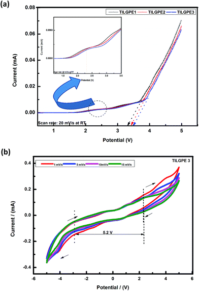 | ||
| Fig. 9 (a) Linear sweep voltammogram of TILGPE1, TILGPE2 and TILGPE3 (b) cyclic voltammogram of high conducting TILGPE3 at different scan rates. | ||
In order to validate our obtained LSV results as well as to understand the ESW of gel polymer electrolyte, we have performed cyclic voltammetry (CV) measurement at 298 K. Among the three electrolytes, TILGPE3 is of an ultimate interest due to its high conducting property at ambient and elevated temperatures. Hence, in order to understand the ESW of electrolyte system and to know the effect of electrolyte mixture LiSCN/EMImSCN upon this stability, a symmetrical cell Li/TILGPE3/Li coin cell was subjected to CV analysis. Fig. 9(b) shows the typical cyclic voltammograms of TILGPE3 electrolyte system recorded at different scan rates (1, 5, 10, and 15 mV s−1). The TILGPE3 must not suffer any redox reaction and it doesn't contain any peaks in the operating potential range of the battery, which is set by the potential difference between anode and cathode. Also, it is observed from the voltammogram that it does not show any breakdown or abrupt current enhancement during cycling. This result indicates that the prepared TILGPE3 is electrochemically stable in the operating voltage of battery (1 to 3.5 V) which is in accordance with earlier reported results by Ravi et al.32 Further, CV graph clearly demonstrate that an increase in the scan rate doesn't affect the position and intensity of the voltammogram curve an remains almost constant, which denotes the good reversibility of the TILGPE3. The obtained result suggests that the TILGPE3 is electrochemically active and it is perfectly fit for battery applications. The acquired findings are in consistent with the result reported earlier.42,44,57
3.5. Battery performance of LiFePO4/TILGPE/Li cell
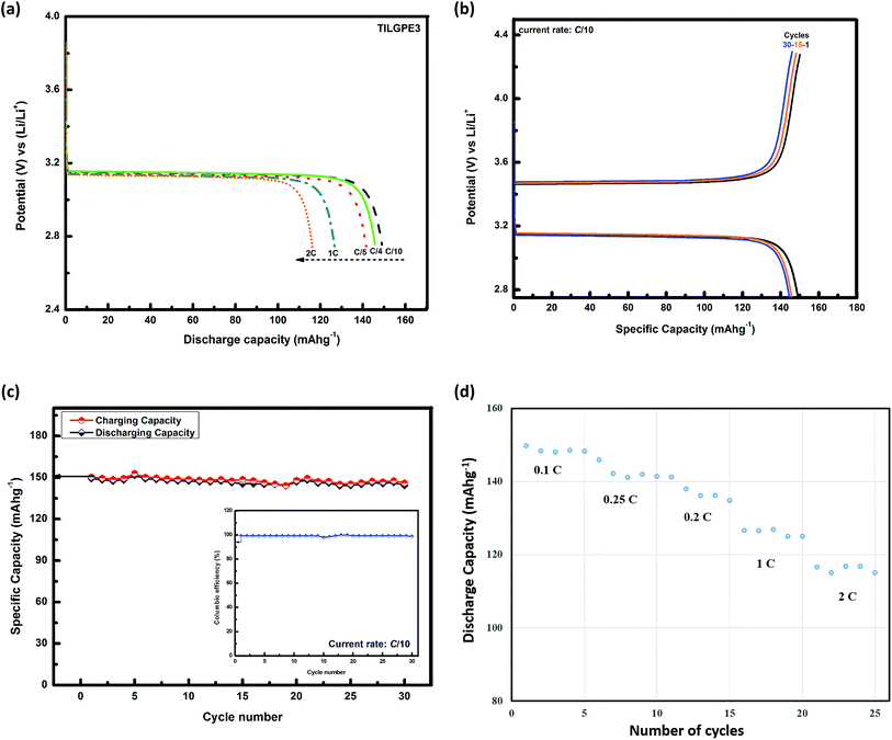
The high conducting nature of TILGPE3 and their high thermal an electrochemical stability paves way to be a promising candidate along with lithium anode and LiFePO4 cathode in the lithium ion batteries. Taking into consideration of the promising practical applications of the TILGPE3 electrolyte, it was assembled in a LiFePO4/Li coin cell. In order to explore the rate performance of the prepared gel electrolyte, the high conducting TILGPE3 was cycled at different current (C) rates at 298 K as shown in Fig. 10(a). As shown in Fig. 10(a), as the C-rate increases, the specific discharge capacity decreases slightly. In brief, in the first cycle, the cell delivers discharge capacities of 149.2, 145.8, 141.8, 126.4 and 115.8 mA h g−1 respectively for C/10, C/4, C/5, 1C and 2C current rates which is about 87.6 to 68.1% of the theoretical capacity of the active material LiFePO4.58 The decrease in discharge capacities of gel electrolytes may occur due to the formation of passive layers over the lithium electrode surface during cycling.59Fig. 10(b) shows the typical charge–discharge curves of the assembled lithium ion cells with TILGPE3 membranes at the C-rate of 0.1C. The charge and discharge plateaus are around 3.4 V and 3.1 V respectively which is quite resembles with already reported literature using LiFePO4/Li electrodes.58 Upon continuous cycling, the discharge capacity decreases slightly and the cell to end with a discharge capacity of 144.3 mA h g−1 on thirtieth cycle. Furthermore, a small drop from 149.8 mA h g−1 to 144.3 mA h g−1 in the discharge capacity may due to the formation of a solid electrolyte interface at the surface or electrodes. This is clearly represented in capacity retention curve at C/10 rate as shown in Fig. 10(c). Also, the columbic efficiency of the first cycle is merely 99.2% which increases steadily upon cycling and attains a value of 98.7% in the thirtieth cycle as shown in the inset of Fig. 10(c). Also, the capacity retention curve at different C-rates of LiFePO4/TILGPE3/Li cell is displayed in Fig. 10(d). The prepared LiFePO4/TILGPE3/Li cell possesses very good capacity retention compared to conventional liquid electrolyte (shown in ESI, Fig. S5 and S6†) and it provides a maximum of 149.8 mA h g−1 at C/10 rate. These results clearly demonstrate that the LiFePO4/TILGPE3/Li has a good room temperature cycling performance. The observed findings are in consistent with the earlier reported results.60,61
4. Conclusions
In summary, for the first time, we have prepared a new class of rhodanide anion based ternary gel polymer electrolyte system and characterized for its application in LIBs. Interactions between ions and polymer are confirmed by the IR shifting of the ν(SCN) mode of electrolyte mixture as well as the νa(CF2) mode of PVdF-co-HFP. The thermal stability of the TILGPEs is marginally increased from 251 to 258 °C upon the introducing of electrolyte mixture and TILGPE3 provides better thermal stability over other two electrolytes. It displays a high ionic conductivity of 2.8 × 10⁻² S cm−1 at 398 K along with an electrochemical stability of 5.2 V. Besides, the transference number of gel electrolyte at ambient temperature is much increased. Henceforth, the prepared TILGPEs are thermal stable and electrochemically active, which holds great promise for to lithium-ion battery requiring high safety with excellent electrochemical properties. The prepared LiFePO4/TILGPE3/Li cell possesses very good capacity retention and it provides a maximum of 149.8 mA h g−1 at C/10 rate. We expect that our ternary gel electrolyte system will spur investigation in the scientific community regarding its potential as active separator for applications in future large scale LIBs.Acknowledgements
This work is supported by Global Frontier R&D Program on Center for Multiscale Energy System funded by the National Research Foundation under the Ministry of Science, ICT & Future Planning, Korea (2011-0031570) and by the Korea Center for Artificial Photosynthesis (KCAP) located in Sogang University funded by the Minister of Science, ICT and Future Planning (MSIP) through the National Research Foundation of Korea (No. 2009-0093883) and also supported by the Human Resources Development program (No. 20114010203090) of the Korea Institute of Energy Technology Evaluation and Planning (KETEP) grant funded by the Korea Government Ministry of Trade, Industry and Energy. The author Dr K. K. S. thankfully remembered the help rendered by Dr Amol Uttam Pawar and Kim Katey, Sogang University for their continuous support in characterization studies. The one of the author Dr K. K. S. thankfully acknowledges Dongguk University-Seoul for their financial support.References
- J. M. Tarascon, A. S. Gozdz, C. Schmutz, F. Shokoohi and P. C. Warren, Solid State Ionics, 1996, 86–88, 49–54 CrossRef CAS.
- J. B. Goodenough and Y. Kim, Chem. Mater., 2010, 587–603 CrossRef CAS.
- F. Groce, F. Gerace, G. Dautzemberg, S. Passerini, G. B. Appetecchi and B. Scrosati, Electrochim. Acta, 1994, 39, 2187–2194 CrossRef.
- S. Ferrari, E. Quartarone, P. Mustarelli, A. Magistris, M. Fagnoni, S. Protti, C. Gerbaldi and A. Spinella, J. Power Sources, 2010, 195, 559–566 CrossRef CAS.
- A. Fernicola, F. C. Weise, S. G. Greenbaum, J. Kagimoto, B. Scrosati and A. Soleto, J. Electrochem. Soc., 2009, 156, A514–A520 CrossRef CAS PubMed.
- V. Gentili, S. Panero, P. Reale and B. Scrosati, J. Power Sources, 2007, 170, 185–190 CrossRef CAS.
- M. Li, L. Yang, S. Fang, S. Dong, S. I. Hirano and K. Tachibana, Polym. Int., 2012, 61, 259–264 CrossRef CAS.
- (a) G. T. Kim, G. B. Appetecchi, M. Carewska, M. Joost, A. Balducci, M. Winter and S. Passerini, J. Power Sources, 2010, 195, 6130–6137 CrossRef CAS; (b) W. Wen, J. M. Wu, Y.-Z. Jiang, J.-Q. Bai and L.-L. Lai, J. Mater. Chem. A, 2016, 4, 10593–10600 RSC; (c) W. Wen, J. M. Wu and M.-H. Cao, Nano Energy, 2016, 2, 1383–1390 CrossRef.
- M. Armand, F. Endres, D. R. MacFarlane, H. Ohno and B. Scrosati, Nat. Mater., 2009, 8, 621–629 CrossRef CAS PubMed.
- M. A. Navarra, MRS Bull., 2013, 38, 548–553 CrossRef CAS.
- M. A. Navarra, J. Manzi, L. Lombardo, S. Panero and B. Scrosati, ChemSusChem, 2011, 4, 125–130 CrossRef CAS PubMed.
- S. R. Sivakkumar and D.-W. Kim, J. Electrochem. Soc., 2007, 154, A134–A139 CrossRef CAS.
- D. R. MacFarlane, N. Tachikawa, M. Forsyth, J. M. Pringle, P. C. Howlett, G. D. Elliott, J. H. Davis, M. Watanabe, P. Simon and C. A. Angell, Energy Environ. Sci., 2014, 7, 232–250 CAS.
- G. B. Appetecchi, M. Montanino, A. Balducci, S. F. Lux, M. Winter and S. Passerini, J. Power Sources, 2012, 219, 371 CrossRef CAS.
- N. K. Karan, O. K. Pradhan, R. Thomas, B. Natesan and R. S. Katiyar, Solid State Ionics, 2008, 179, 689–696 CrossRef CAS.
- G. Derrien, J. Hassoun, S. Sacchetti and S. Panero, Solid State Ionics, 2009, 180, 1267–1271 CrossRef CAS.
- H. Lee, M. Yanilmaz, O. Toprakci, K. Fu and X. Zhang, Energy Environ. Sci., 2014, 7, 3857–3886 CAS.
- Y. Zhu, F. Wang, L. Liu, S. Xiao, Y. Yang and Y. Wu, Sci. Rep., 2013, 3, 3187 Search PubMed.
- C. M. Costa, M. M. Silva and S. Lanceros-Méndez, RSC Adv., 2013, 3, 11404–11417 RSC.
- S. M. Seidel, S. Jeschke, P. Vettikuzha and H.-D. Wiemhöfer, Chem. Commun., 2015, 51, 12048–12051 RSC.
- A. Kumar, R. Sharma, M. K. Das, P. Gajbhiye and K. K. Kar, Electrochim. Acta, 2016, 215, 1–11 CrossRef CAS.
- H. Gao, B. Guo, J. Song, K. Park and J. B. Goodenough, Adv. Energy Mater., 2015, 5, 1–8 Search PubMed.
- N. Zebardastan, M. H. Khanmirzaei, S. Ramesh and K. Ramesh, Electrochim. Acta, 2016, 220, 573–580 CrossRef CAS.
- K. Karuppasamy, H. W. Rhee, P. A. Reddy, D. Gupta, L. Mitu, A. R. Polu and X. Sahaya Shajan, J. Ind. Eng. Chem., 2016, 40, 1–9 CrossRef.
- S. K. Chaurasia, R. K. Singh and S. Chandra, J. Phys. Chem. B, 2013, 117, 897–906 CrossRef PubMed.
- S. K. Chaurasia, V. K. Singh and R. K. Singh, J. Mater. Chem. C, 2015, 3, 7305–7318 RSC.
- G. P. Pandey, T. Liu, C. Hancock, Y. Li, X. S. Sun and J. Li, J. Power Sources, 2016, 328, 510–519 CrossRef CAS.
- K. Karuppasamy, P. A. Reddy, G. Srinivas, A. Tewari, R. Sharma, X. S. Shajan and D. Gupta, J. Membr. Sci., 2016, 514, 350–357 CrossRef CAS.
- A. S. Pensado, M. Brehm, J. Thar, A. P. Seitsonen and B. Kirchner, ChemPhysChem, 2012, 13, 1845–1853 CrossRef CAS PubMed.
- G. Hua Sun, K. Xi Li and C. Gong Sun, J. Power Sources, 2006, 162, 1444–1450 CrossRef.
- M. Ravi, S. Song, J. Wang, R. Nadimicherla and Z. Zhang, Ionics, 2016, 22, 661–670 CrossRef CAS.
- (a) M. Ravi, S. Song, K. Gu, J. Tang and Z. Zhang, Mater. Sci. Eng., B, 2015, 195, 74–83 CrossRef CAS; (b) A. Hauch and A. Georg, Electrochim. Acta, 2001, 46, 3457–3466 CrossRef CAS; (c) J. Zhang, X. Huang, H. Wei, J. Fu, W. Liu and X. Tang, New J. Chem., 2011, 35, 614–621 RSC.
- R. M. Silverstein, F. X. Webster and D. J. Kimele, Spectroscopic Identifications of Organic Compounds, 7th edn, 2005 Search PubMed.
- P. Periasamy, K. Tatsumi, M. Shikano, T. Fujieda, Y. Saito, T. Sakai, M. Mizuhata, A. Kajinami and S. Deki, J. Power Sources, 2000, 88, 269–273 CrossRef CAS.
- Q. Zhang, F. Ding, W. Sun and L. Sang, RSC Adv., 2015, 5, 65395–65401 RSC.
- S. Rajendran, O. Mahendran and T. Mahalingam, Eur. Polym. J., 2002, 38, 49–55 CrossRef CAS.
- M. Suleman, Y. Kumar and S. A. Hashmi, Mater. Chem. Phys., 2015, 1–11 Search PubMed.
- S. Ganesan, B. Muthuraaman, V. Mathew, M. K. Vadivel, P. Maruthamuthu, M. Ashokkumar and S. A. Suthanthiraraj, Electrochim. Acta, 2011, 56, 8811–8817 CrossRef CAS.
- S. Shalu, L. Balo, H. Gupta, V. kumar Singh and R. K. Singh, RSC Adv., 2016, 6, 73028–73039 RSC.
- R. He and T. Kyu, Macromolecules, 2016, 49, 5637–5648 CrossRef CAS.
- S. U. Hong, D. Park, Y. Ko and I. Baek, Chem. Commun., 2009, 7227–7229 RSC.
- M. Suleman, Y. Kumar and S. A. Hashmi, J. Phys. Chem. B, 2013, 117, 7436–7443 CrossRef CAS PubMed.
- W. Li, Y. Xing, X. Xing, Y. Li, G. Yang and L. Xu, Electrochim. Acta, 2013, 112, 183–190 CrossRef CAS.
- D. Kumar and S. A. Hashmi, Solid State Ionics, 2010, 181, 416–423 CrossRef CAS.
- H. Kim, S. Park and M. Cho, Phys. Chem. Chem. Phys., 2012, 14, 6233 RSC.
- L. N. Sim, S. R. Majid and A. K. Arof, Solid State Ionics, 2012, 209–210, 15–23 CrossRef CAS.
- M. H. Abdul Rahaman, M. U. Khandaker, Z. R. Khan, M. Z. Kufian, I. S. M. Noor and A. K. Arof, Phys. Chem. Chem. Phys., 2014, 16, 11527–11537 RSC.
- K. Karuppasamy, S. Thanikaikarasan, R. Antony, S. Balakumar and X. S. Shajan, Ionics, 2012, 18, 737–745 CrossRef CAS.
- (a) K. Karuppasamy, C. Vijil Vani, R. Antony, S. Balakumar and X. Sahaya Shajan, Polym. Bull., 2013, 70, 2531–2545 CrossRef CAS; (b) S. Abbrent, J. Lindgren, J. Tegenfeldt and A. Ê. Wendsjo, Electrochim. Acta, 1998, 43, 1185–1191 CrossRef CAS.
- (a) P. Yang, W. Cui, L. Li, L. Liu and M. An, Solid State Sci., 2012, 14, 598–606 CrossRef CAS; (b) H. Akashi, K. Tanaka and K. Sekai, J. Electrochem. Soc., 1998, 145, 881–886 CrossRef CAS.
- J. R. Kim, S. W. Choi, S. M. Jo, W. S. Lee and B. C. Kim, J. Electrochem. Soc., 2005, 152, A295 CrossRef CAS.
- P. Raghavan, X. Zhao, H. Choi, D. H. Lim, J. K. Kim, A. Matic, P. Jacobsson, C. Nah and J. H. Ahn, Solid State Ionics, 2014, 262, 77–82 CrossRef CAS.
- J. Evans, C. A. Vincent and P. G. Bruce, Polymer, 1987, 28, 2324–2328 CrossRef CAS.
- J. R. Nair, D. Cíntora-Juárez, C. Pérez-Vicente, J. L. Tirado, S. Ahmad and C. Gerbaldi, Electrochim. Acta, 2016, 199, 172–179 CrossRef CAS.
- J. H. Shin, W. A. Henderson and S. Passerini, Electrochem. Commun., 2003, 5, 1016–1020 CrossRef CAS.
- I. Stepniak, E. Andrzejewska, A. Dembna and M. Galinski, Electrochim. Acta, 2014, 121, 27–33 CrossRef CAS.
- J. K. Chang, M. T. Lee, W. T. Tsai, M. J. Deng, H. F. Cheng and I. W. Sun, Langmuir, 2009, 25, 11955–11960 CrossRef CAS PubMed.
- Y. Wang, P. He and H. Zhou, Energy Environ. Sci., 2011, 4, 805–817 CAS.
- T. Eriksson, A. M. Andersson, A. G. Bishop, C. Gejke, T. Gustafsson and J. O. Thomas, J. Electrochem. Soc., 2002, 149, A69–A78 CrossRef CAS.
- Y. Lin, J. Li, Y. Lai, C. Yuan, Y. Cheng and J. Liu, RSC Adv., 2013, 3, 10722 RSC.
- J. Zhang, B. Sun, X. Huang, S. Chen and G. Wang, Sci. Rep., 2014, 4, 6007 CrossRef CAS PubMed.
Footnote |
| † Electronic supplementary information (ESI) available. See DOI: 10.1039/c7ra01081h |
| This journal is © The Royal Society of Chemistry 2017 |

![[thin space (1/6-em)]](https://www.rsc.org/images/entities/char_2009.gif)
