
 Open Access Article
 This Open Access Article is licensed under a
 Creative Commons Attribution 3.0 Unported Licence
A high rate and stable electrode consisting of a Na3V2O2X(PO4)2F3−2X–rGO composite with a cellulose binder for sodium-ion batteries†
P. Ramesh Kumara,
Young Hwa Jung b,
Syed Abdul Ahada and
Do Kyung Kim*a
b,
Syed Abdul Ahada and
Do Kyung Kim*a
aDepartment of Materials Science and Engineering, Korea Advanced Institute of Science and Technology (KAIST), 291 Daehak-ro, Yuseong-gu, Daejeon 34141, Republic of Korea. E-mail: dkkim@kaist.ac.kr
bBeamline Division, Pohang Accelerator Laboratory (PAL), Pohang 37673, Republic of Korea
First published on 19th April 2017
Abstract
Sodium ion batteries are a promising alternative to conventional lithium-ion batteries, mostly for large scale energy storage applications. In this paper, we report sodium vanadium oxy-fluorophosphate as a cathode material for sodium-ion batteries with 8.0 wt% reduced graphene oxide (rGO), synthesized via solid state reaction followed by a hydrothermal method. The newly reported Na3V2O2X(PO4)2F3−2X–rGO (NVOPF–rGO) composite with a hydrophilic carboxymethyl cellulose sodium (CMC-Na) binder shows enhanced rate performance and highly stable cyclability; it delivers a stable reversible capacity of 108 mA h g−1 in a sodium half-cell, and it exhibits 98% capacity retention at a 0.1C rate over 250 cycles. Furthermore, the as-prepared NVOPF–rGO composite exhibits discharge capacities of 98 mA h g−1 and 64 mA h g−1 at 0.2C and 2C rates, respectively, in a full-cell configuration with a NaTi2(PO4)3–MWCNT (NTP–M) anode for 1000 cycles.
1. Introduction
Lithium ion batteries (LIBs) have been employed widely in portable electronic devices. Still, these face some challenges for use in automotive applications. The challenges in the development of LIBs for the potential markets of electric vehicles (EVs) and hybrid electric vehicles (HEVs) are the low abundance of lithium in the earth’s crust resulting in a high cost, and the low safety, average energy density and low rate capability.1 In the process of finding a lithium alternative high energy storage system, researchers have focused on sodium ion batteries because sodium resources are abundant and available everywhere around the world.2 Furthermore, the electrochemical reaction behaviors and standard potential of sodium are more suitable for battery applications, therefore sodium-ion batteries are beginning to receive widespread attention. In sodium ion batteries, the cathode is the costliest component of the cell, which is typically a transition metal oxide with high electronic and ionic conductivity. Presently, phosphate polyanionic open framework materials have been investigated as cathode materials for high-energy sodium ion batteries due to their structural and thermal stability.3,4 In a phosphate polyanionic structure, oxygen atoms are fixed in the [PO4]3− structure to limit oxygen liberation, which leads to high thermal stability. Also, the incorporation of [PO4]3− groups can raise the redox potential of the materials by an inductive effect. Altogether these factors are quite capable of contributing an exceptional electrochemical and structural stability as compared to other metal oxides. To date, several sodium fluorophosphates have been investigated as possible cathodes of a Na-ion battery: NaVPO4F, Na3V2O2(PO4)2F, Na3V2O2X(PO4)2F3−2X, Na2MPO4F [M = Fe, Mn & Co], Na3V2(PO4)2F3, Na3V2O2(PO4)2F, and Li1.1Na0.4VPO4.8F0.7.5–10 Among these, Na3V2O2X(PO4)2F3−2X is particularly attractive because of its high theoretical capacity (130 mA h g−1), with two Na+ per formula unit and high structural stability (<2% volume change during cycling).Rojo et al. reported Na3V2O2X(PO4)2F3−2X (0 ≤ X ≤ 1) for the first time, and they have synthesized it using different amounts and types of carbon with the aim of studying the influence of carbon on the properties of these materials.11,12 At the same time, the Kang group used a combined theoretical and experimental approach to determine the detailed reaction mechanisms of Na3V2O2X(PO4)2F3−2X cathodes.13 Nevertheless, oxy-fluorophosphates suffer from low electronic conductivity at room temperature and bigger particle sizes when obtained through a conventional solid state reaction, which is the only process adopted to synthesize these materials to date. Recently, our group has reported a Na3V2O2X(PO4)2F3−2X–MWCNT composite as a cathode material for rechargeable non-aqueous and aqueous sodium-ion batteries, which was made by a combination of solid state and hydrothermal reactions.14 In addition to the electrochemical properties of the electro-active material, the binder also plays a significant role in stabilizing the electrode during continuous electrochemical cycling. A literature survey suggests that the nature of the bonding of the active particles in the electrodes is important for rate capability and cyclic stability.15
In current non-aqueous alkali ion battery technologies, polyacrylic acid (PAA), polyvinylidene fluoride (PVDF), polyvinyl pyrrolidone (PVP), carboxymethyl cellulose lithium or sodium (CMC-Li, Na), and Na-alginate have been used as binders to prepare electrodes.16–18 Among these, CMC has a higher stiffness, which can make it the most appropriate binder for a positive intercalation electrode design. CMC is a derivative of cellulose, consisting of β-linked glucopyranose residues with varying levels of carboxymethyl (–CH2COO–) substitution. CMC contains a higher concentration of carboxylic functional groups, which offers superior performance as a binder by maintaining the integrity of the whole electrode during cycling.19 Researchers found that negative electrodes made with CMC-Na showed less irreversible capacity loss and higher conductivity than other conventional binders.20–23
In this work, a composite with reduced graphene oxide (rGO) was prepared to boost the electrochemical properties of the cathode material, Na3V2O2X(PO4)2F3−2X, via a combination of solid state and hydrothermal reactions. The Na3V2O2X(PO4)2F3−2X–rGO composite was prepared in the shape of micro-squares and has been characterized using different techniques like XRD, Raman, TEM, and NMR. Furthermore, electrochemical properties were analyzed using two different binders, one was conventional polyvinylidene fluoride (PVDF), and the other one was carboxymethyl cellulose (CMC-Na). The CMC binder provides a stable chemical interaction with Na3V2O2X(PO4)2F3−2X–rGO composites and could enhance the electrochemical performance through combining with rGO for these low electronic conductivity electrode materials. Finally, we have shown the NaTi2(PO4)3–MWCNT (NTP–M)//Na3V2O2X(PO4)2F3−2X–rGO (NVOPF–rGO) full-cell to confirm the possibility for real Na-ion battery applications.
2. Experimental section
2.1. Synthesis and characterization of the NVOPF–rGO composites
The NVOPF–rGO composite was prepared under mild hydrothermal conditions by reacting NaF and [V(PO3)3]n in a 3.3![[thin space (1/6-em)]](https://www.rsc.org/images/entities/char_2009.gif) :1 molar ratio. The reaction mixture was sealed in a polytetrafluoroethylene (PTFE)-lined steel pressure vessel, which was kept at 170 °C for 72 h. The rGO prevents complete oxidation from V3+ to V4+ in an aqueous medium. Before this, we prepared the [V(PO3)3]n–rGO composite using a solid state reaction with stoichiometric amounts of V2O5 and NH4H2PO4, and GO which acts as a reducing agent. The graphene oxide was prepared by a modified Hummers’ method.20 This mixture was annealed twice under an N2 atmosphere at 300 and 850 °C for 6 h. All of the chemicals were procured from Sigma-Aldrich and used without any further purification. Illustration of the NVOPF–rGO composite synthesis process is shown in Fig. 1. The preparation of the Na3V2O2X(PO4)2F3−2X–rGO composite can be explained using the following reactions:
:1 molar ratio. The reaction mixture was sealed in a polytetrafluoroethylene (PTFE)-lined steel pressure vessel, which was kept at 170 °C for 72 h. The rGO prevents complete oxidation from V3+ to V4+ in an aqueous medium. Before this, we prepared the [V(PO3)3]n–rGO composite using a solid state reaction with stoichiometric amounts of V2O5 and NH4H2PO4, and GO which acts as a reducing agent. The graphene oxide was prepared by a modified Hummers’ method.20 This mixture was annealed twice under an N2 atmosphere at 300 and 850 °C for 6 h. All of the chemicals were procured from Sigma-Aldrich and used without any further purification. Illustration of the NVOPF–rGO composite synthesis process is shown in Fig. 1. The preparation of the Na3V2O2X(PO4)2F3−2X–rGO composite can be explained using the following reactions:| 0.5V2O5 + 3NH4H2PO4 + GO → [(VPO3)3]n/rGO + 3NH3 + CO + 4.5H2O |
| 4[(VPO3)3]n/rGO + 6NaF + 22xO2 + 44xH2O → 2Na3V2O2X(PO4)2F3−2X/rGO + 4xHF + 8H3PO4 |
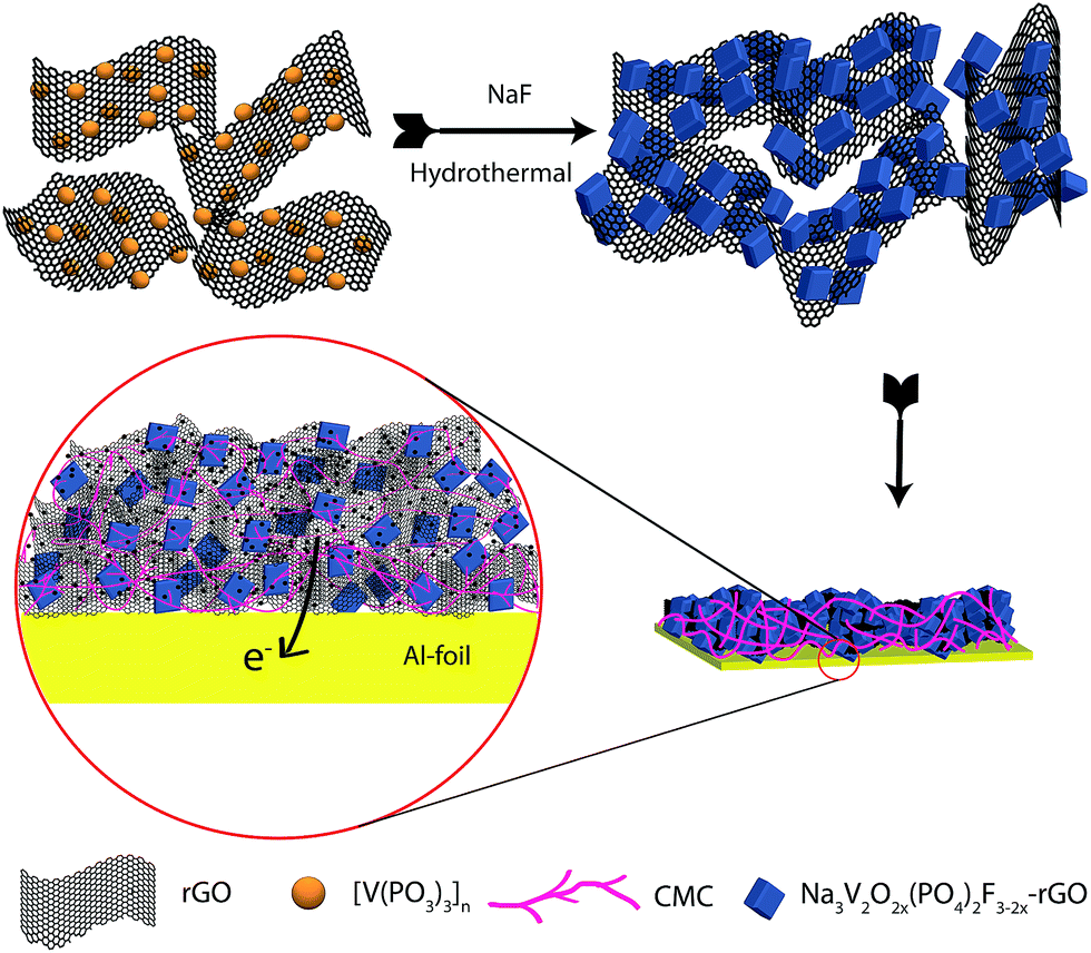 | ||
| Fig. 1 An illustration of the synthesis of the NVOPF–rGO composite from [V(PO3)3]n–rGO. | ||
2.2. Preparation of the NTP–M composite anode material
Stoichiometric amounts of NaH2PO4·H2O, TiO2, and NH4H2PO4 were mixed with 10 wt% multi-walled carbon nanotubes (CM 95, Iljin Nanotech Co. Ltd). It is worth mentioning that there are no metallic impurities in the carbon nanotubes according to the information from the manufacturer. After grinding and mixing the reagents in a mortar for 1 h, the mixture was placed in a ceramic crucible covered with graphite foil to avoid contamination and was fired at 900 °C for 10 h under an argon atmosphere.2.3. Characterization
X-ray analysis was employed in order to confirm the purity of the NVOPF–rGO and NTP–M composite powders using a powder X-ray diffractometer (Rigaku D/Max-2500) with a Cu X-ray (λ = 1.5418 Å) at room temperature. The final and exact phase of the Na3V2O2X(PO4)2F3−2X/rGO composite was confirmed using high resolution synchrotron powder X-ray diffraction (SPXRD) data from the 9B HRPD beamline of PLS-II (Pohang, Republic of Korea). The SPXRD data were collected at room temperature with 2θ ranging from 10° to 130° with a step size of 0.01° at a wavelength of λ = 1.5177 Å. The particle sizes and morphologies were characterized using a field emission scanning electron microscope (FE-SEM Hitachi S-4800, Japan). The Raman spectra of the powders were recorded at room temperature on a HR 800 Raman spectrophotometer (Jobin Yvon-Horiba, France) using a monochromatic He–Ne laser (514 nm) operating at 20 mW. Elemental analysis was carried out using a Thermo Scientific Flash 2000 Series element analyser. 23Na solid state NMR spectra were recorded on a Bruker Advance 400 MHz spectrometer at room temperature.2.4. Electrochemical testing
The electrochemical studies of the as-synthesized NVOPF–rGO composite were conducted in CR2032 coin cells. The composite electrode was prepared by mixing 80 wt% of the active materials with 10 wt% Super P carbon and 10 wt% polyvinylidene fluoride (PVDF) or carboxymethyl cellulose sodium (CMC-Na) binders in a suitable solvent. The obtained slurry was coated on Al foil and cut into circular electrodes with diameters of 12 mm. Sodium metal was used as an anode, and 1 M NaClO4 in propylene carbonate (PC) with 2 v/v% fluoroethylene carbonate (FEC) was used as the electrolyte. The coin cells were assembled in an argon-filled dry glove box using a borosilicate glass fibre separator (Whatman GF/D). For the full-cell tests, the NTP–M composite on the 14 mm Al foil was used as the anode for testing the Na-ion full-cells. The cathode loading and area for the NVOPF–rGO composite electrode were ∼1.3 mg and 1.13 cm−2, respectively, and the anode loading and area for the NTP–M composite electrode were ∼2.2 mg and 1.54 cm−2, respectively.Cyclic voltammetry and galvanostatic cycling of the Na-ion full-cells were measured using a potentiostat VMP3 (Biologic, France). The Na coin half-cells were galvanostatically cycled between 2.5 V and 4.5 V using an automatic battery cycle tester WBCS3000 (Wonatech, Korea). The NTP–M//NVOPF–rGO full-cell was cycled from 1.0 V to 2.5 V at rates of 0.2C and 2C based on the cathode active material weight.
3. Results & discussion
3.1. Structural & microstructural characterization
Fig. S1† shows the XRD patterns of the [V(PO3)3]n–rGO and NVOPF–rGO composites along with their JCPDS data. No impurities or residues have been detected in the XRD patterns, as shown in Fig. S1,† indicating the high purity of the prepared material. In order to more accurately analyse the phase of the as-prepared composites, full-pattern matching was performed on the synchrotron XRD patterns using the pseudo-Voigt profile function in the FullProf Suite24 as shown in Fig. 2.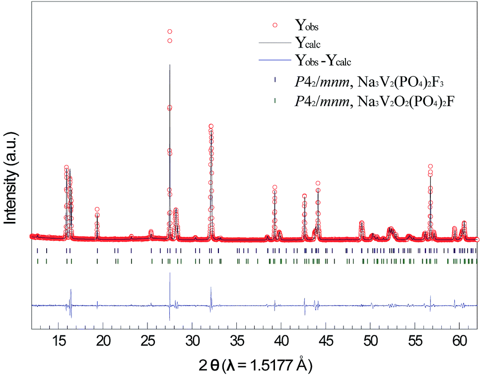 | ||
| Fig. 2 Synchrotron XRD data and whole pattern fitting of the NVOPF–rGO composite. | ||
The fitting was initiated from two phases, Na3V2(PO4)2F3 (P42/mnm)5 and Na3V2O2(PO4)2F (P42/mnm),25 as previously reported. The lattice parameters in the whole pattern fitting of Na3V2O2X(PO4)2F3−2X/rGO are refined to be a = 9.02694(5) Å, c = 10.71806(8) Å, and V = 873.368(10) Å3 in P42/mnm (Na3V2(PO4)2F3) and a = 9.03393(2) Å, c = 10.61518(6) Å, and V = 866.324(5) Å3 in P42/mnm (Na3V2O2(PO4)2F). Therefore, the as-prepared Na3V2O2X(PO4)2F3−2X/rGO composite is a mixed phase of both Na3V2(PO4)2F3 and Na3V2O2(PO4)2F, indicating that the oxidation state of V is between +3 and +4. This oxidation state may have originated from the two-step synthesis of the composite as explained in the experimental section.26,27
The SEM and TEM images are presented in Fig. 3 at different magnifications. From Fig. 3a it is clearly observed that there is a uniform distribution of rGO in the Na3V2O2X(PO4)2F3−2X squares, which will help to increase the electronic conductivity of the electrode materials. The average diagonal length of the smooth edge Na3V2O2X(PO4)2F3−2X squares is around 2 μm. Furthermore, the TEM image in Fig. 3b also shows the square-particle and the interaction between the rGO and the Na3V2O2X(PO4)2F3−2X in this composite. The carbon percentage in the composite was measured using an Element Analyser, and the value is ca. 8 wt%.
 | ||
| Fig. 3 (a) SEM and (b) TEM images of the NVOPF–rGO composite. | ||
The Raman spectroscopy results for both [V(PO3)3]n–rGO and the NVOPF–rGO composite are shown in Fig. S2.† Both samples exhibit the same set of peaks in the spectra. At the higher end, peaks at 2700 and 2910 cm−1 correspond to the G′ and D + G bands. Another two high intensity bands at 1350 and 1580 cm−1 appear, corresponding to the disordered (D) and graphite (G) bands of carbon-based materials. Both samples display a similar ratio of D-band and G-band intensities for [V(PO3)3]n–rGO (ID/IG = 1.36) and NVOPF–rGO (ID/IG = 1.22), which indicates the relatively small size of the ordered domains.28 In addition to these peaks, an additional two peaks were observed in the Raman spectrum of the NVOPF–rGO composite at 930 and 1040 cm−1, due to the symmetric P–O stretching vibration and anti-symmetric stretching band of PO4, respectively.8
Fig. S3† shows the 23Na solid-state NMR spectrum of the NVOPF–rGO composite (ESI†). The three top signals at 95, 126, and 172 ppm are fitted with relative intensities of 44%, 31%, and 25%, respectively. The observed chemical shifts indicate the presence of hyperfine interactions between the 23Na and the paramagnetic V ions.29,30 Three signals observed in the spectrum were assigned to the V4+–V4+ (100 ppm), V3+–V4+ (128 ppm), and V3+–V3+ (169 ppm) pairs. After fitting the data, we obtain an average oxidation state of the vanadium in the NVOPF–rGO composite of V3.54+.
Finally, based on the NMR results we have proposed Na3V2O1.08(PO4)2F1.92 as the final formula for the as-prepared composite material.11
Hence, the XRD, SEM, TEM, Raman, and 23Na solid-state NMR results confirm the phase, purity, and uniform distribution of rGO over the Na3V2O2X(PO4)2F3−2X micro squares.
3.2. Electrochemical properties
Fig. 4 shows the charge/discharge capacities of the NVOPF–rGO cathode with a PVDF binder in a Na half-cell for 60 cycles. NVOPF–rGO delivers an initial discharge capacity of 103 mA h g−1 at the 0.1C (13 mA g−1) rate, and the discharge capacity value is 87 mA h g−1 after 60 cycles (84% of the initial capacity retained). The inset of Fig. 4 presents the corresponding capacity–voltage profiles of the NVOPF–rGO composite with a PVDF binder. The charge/discharge profiles show that there are two plateaus with average voltages of about 3.6 V and 4.1 V. The average voltage of NVOPF–rGO (∼3.9 V) is one of the highest among cathode materials. The oxidation and reduction potentials were further confirmed by the CV plot for the NVOPF–rGO composite with a PVDF binder, which is shown in Fig. S4.†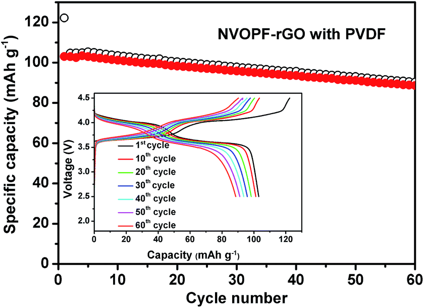 | ||
| Fig. 4 Cyclability of the NVOPF–rGO cathode with a PVDF binder in a Na half-cell for 60 cycles. The charge/discharge curves are shown in the inset figure. | ||
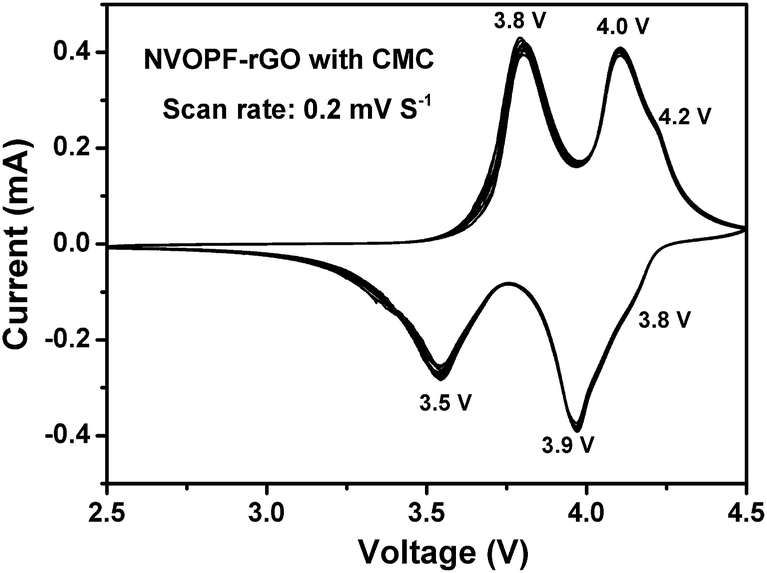
Fig. 5 shows the CV plot for the NVOPF–rGO composite with a CMC binder for 20 cycles. In Fig. 5, three sets of anodic and cathodic peaks are observed. The three redox peaks at 4.1/4.2 V, 3.8/4.0 V, and 3.5/3.8 V indicate the presence of the mixed phase between Na3V2O2(PO4)2F and Na3V2(PO4)2F3, as confirmed by the XRD and NMR results, like our previous paper.14
 | ||
| Fig. 5 The CV plot for the NVOPF–rGO composite with a CMC-Na binder for 20 cycles at a scan rate of 0.2 mV S−1. | ||
The cycling performance of the NVOPF–rGO composite with a CMC-Na binder is shown in Fig. 6. From Fig. 6a, it can be seen that the NVOPF–rGO composite with a CMC binder maintained a stable discharge capacity of 108 mA h g−1 with 98% capacity retention over 250 cycles. The charge–discharge profiles for the NVOPF–rGO composite with a CMC binder for 250 cycles are represented in Fig. 6b. The voltage profile shows two significant plateau regions. The electrode with a CMC binder shows a considerable performance even at different high current rates. The discharge capacity at various current rates of 130 mA g−1 (1C), 260 mA g−1 (2C), 650 mA g−1 (5C), 1300 mA g−1 (10C), and 2600 mA g−1 (20C), and then reverting back to the 1C rate for each 10 cycles is shown in Fig. 7.
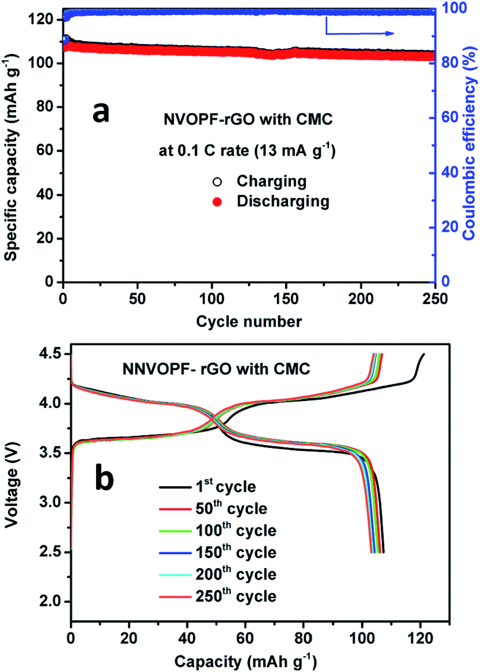 | ||
| Fig. 6 (a) Cycling performance and (b) charge–discharge cycles of the NVOPF–rGO composite with a CMC-Na binder for 250 cycles. | ||
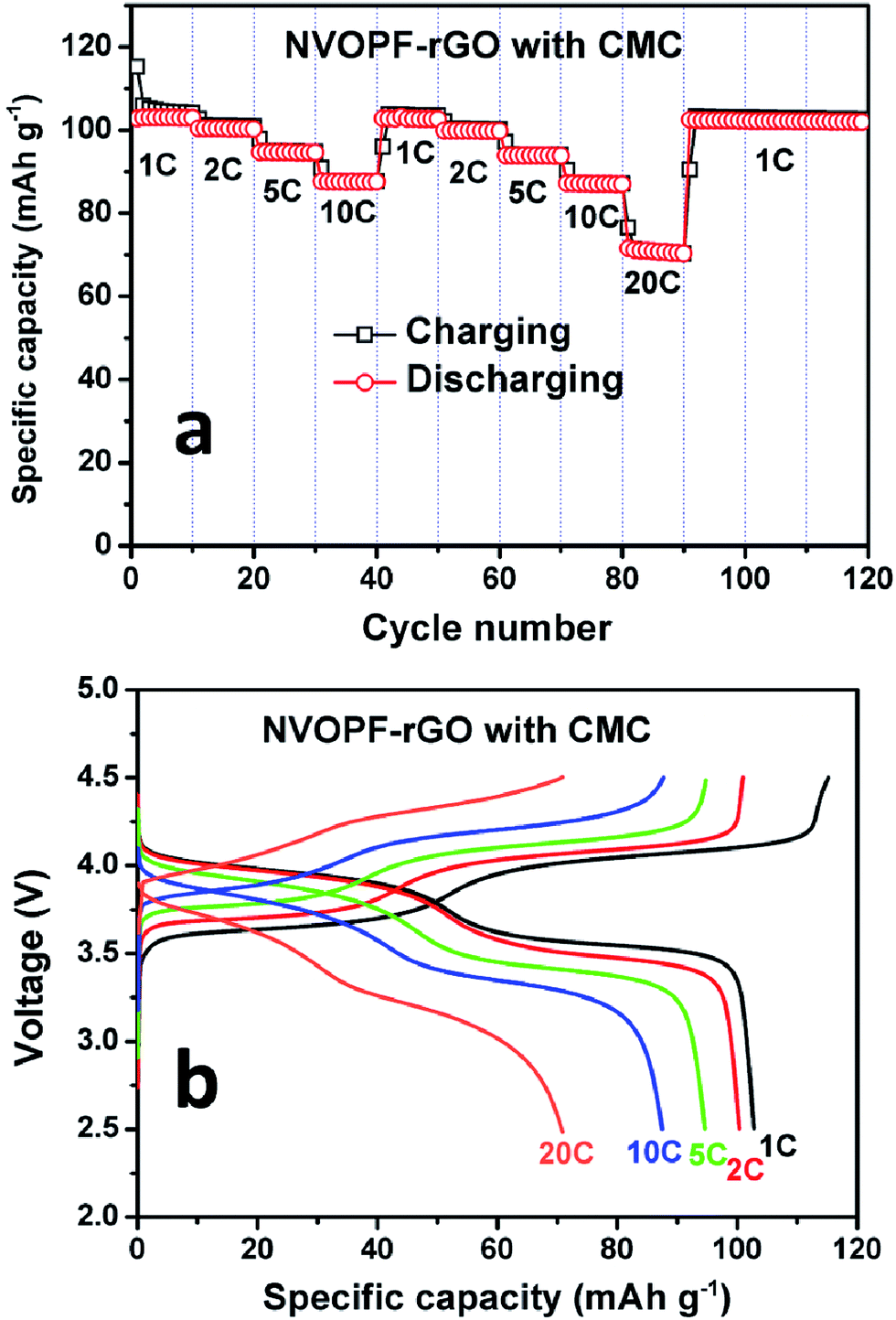 | ||
| Fig. 7 (a) Rate capability and (b) charge–discharge cycles of the NVOPF–rGO composite with CMC at different C-rates. | ||
Even at a very high current rate (20C), the NVOPF–rGO composite with a CMC-Na binder shows a stable capacity of 72 mA h g−1. Such impressive sodium storage properties with the CMC-Na binder may be attributed to better adherence between the active material surfaces and the binder as well as the highly conductive nature of the reduced graphene oxide. Wang et al. suggested that CMC as the binder mixed with cathode material in the water can improve the electronically percolating network.19 The hydrophilic nature of the binder could improve the electrolyte accessibility. Furthermore, CMC-Na will shorten the diffusion pathway to the cathode microparticle surface and improve the efficiency through increasing the amount of freely moving Na+ ions in the cell. Hence, enhancement of the electrochemical properties in the NVOPF–rGO composite with a CMC-Na binder might be due to the Na3V2O2X(PO4)2F3−2X micro squares being well embedded in the highly conductive rGO, the formation of an electronically percolating network during cycling, and strong ester-like bonding between submicron crystalline Na3V2O2X(PO4)2F3−2X materials and the carboxyl groups of the CMC-Na binder.31,32
Electrochemical impedance spectroscopy (EIS) measurements were carried out during the first cycle at different potentials, as shown in Fig. S5.† In Fig. S5† symbols represent the experimental data points and the fitted data are represented by continuous lines for the NVOPF–rGO composite with a CMC binder. The obtained data were analysed via fitting with an equivalent electrical circuit consisting of resistors and constant phase elements, which is shown in Fig. S6.† The equivalent electrical circuit consists of the electrolyte resistance (Re), the separable surface film (RSF) and charge transfer (RCT) resistances, the constant phase elements CPESF and CPECT, and the finite Warburg impedance (Wd). The depressed semi-circles in the spectra (shown in the Fig. S5 insets †) represent a parallel combination of constant phase elements (CPEs) and resistance. The experimental data were fitted using Z-fit software with successful fitting except at low frequencies.
In Fig. S5a,† the NVOPF–rGO with CMC impedance results showed that the electrolyte resistance (Re) remained almost constant at 5.4 Ω while charging. From Fig. S5a,† it can be seen that the Nyquist plot of the cell at OCV consists of a depressed semi-circle followed by a Warburg element at low frequencies. The depressed semi-circle observed in the high-frequency range is related to the formation of the passivation film on the surface (SF) and the charge transfer process at the interface (CT).
At OCV, only the surface film contribution will occur, and this depends on the concentration of the electrolyte. Also, solid electrolyte interphase (SEI) formation/partial dissolution/re-formation takes place on cycling. This is reflected in the changes in the value of the surface film impedance (RSF) upon cycling.33 Also at 3 and 3.5 V, the impedance plots consist of a single semi-circle with a sloping line like that at OCV. At 3.7 V and 4.2 V, the Nyquist plots contain two semi-circles in the high and intermediate frequency range and a sloping line in the low-frequency region, and this indicates de-intercalation of Na ions from the cathode structure. Upon further charging to 4.6 V, the size of the high-frequency semi-circle reduced and the second semi-circle disappears. The Nyquist plots of the NVOPF–rGO with CMC-Na anode during the first discharging state are shown in Fig. S5b.† From Fig. S5b,† it can be seen that at 4 V and 3.7 V, the Nyquist plots contain a high-frequency semi-circle along with a low frequency depressed semi-circle, which is due to intercalation of Na ions into the electrode material. Upon further discharging down to 3.3 V and 2.5 V, the surface film and charge transfer impedances are merged and form one depressed semi-circle. Hence, we concluded that the electrochemical impedance studies could support the observed electrochemical results.
3.3. The NTP–M//NVOPF–rGO Na-ion full-cell
Through the above results, the cathode (NVOPF–rGO) material has shown much improved electrochemical properties with a CMC binder. The Na-ion full-cell was assembled using NTP–M as an anode to demonstrate the feasibility of the NVOPF–rGO micro-squares as a cathode material for real Na-ion battery systems. Fig. 8a shows the cycling performance of an NTP–M//NVOPF–rGO full-cell. The full cell delivers an initial discharge capacity of 98 mA h g−1 at a rate of 0.2C (26 mA g−1). The discharge capacity decreased to 89 mA h g−1 after 100 cycles; however, the charge/discharge efficiency gradually increased to 99% from the first efficiency of 97%.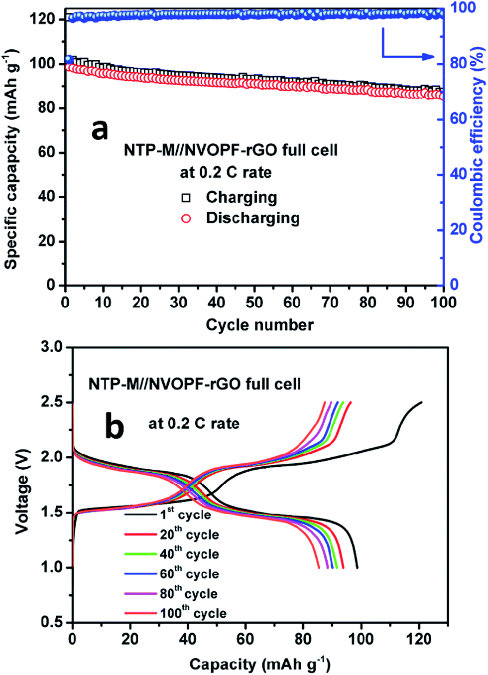 | ||
| Fig. 8 (a) The cycling performance and (b) charge–discharge cycles of the NTP–M//NVOPF–rGO full-cell for 100 cycles at a 0.2C rate. | ||
The cycling stability for a Na-ion full-cell should be enhanced, and this result indicates the feasibility of the NVOPF–rGO electrode as a cathode for Na-ion batteries. The charge–discharge voltage profiles for the full-cell during cycling are presented in Fig. 8b. The typical charge–discharge curves of NVOPF–rGO and NTP–M are shown in Fig. S7.† The average voltage of NVOPF–rGO and NTP–M were about 3.8 and 2.1 V, respectively, thus the expected voltage of the full-cell was around 1.7 V. The window of the working voltage for a full battery was 1.0–2.5 V, which was determined by analysing the working voltages of the cathode and anode. The NTP–M//NVOPF–rGO full-cell showed an average discharging voltage of ∼1.7 V, and the typical voltage profile is well matched with the voltage difference of the NVOPF–rGO and NTP–M half-cell results. NTP–M has shown a flat plateau at ∼2.1 V vs. Na+/Na,34 while Na3V2O2X(PO4)2F3−2X–rGO exhibits two flat plateaus in the voltage profile as shown in Fig. 6b.
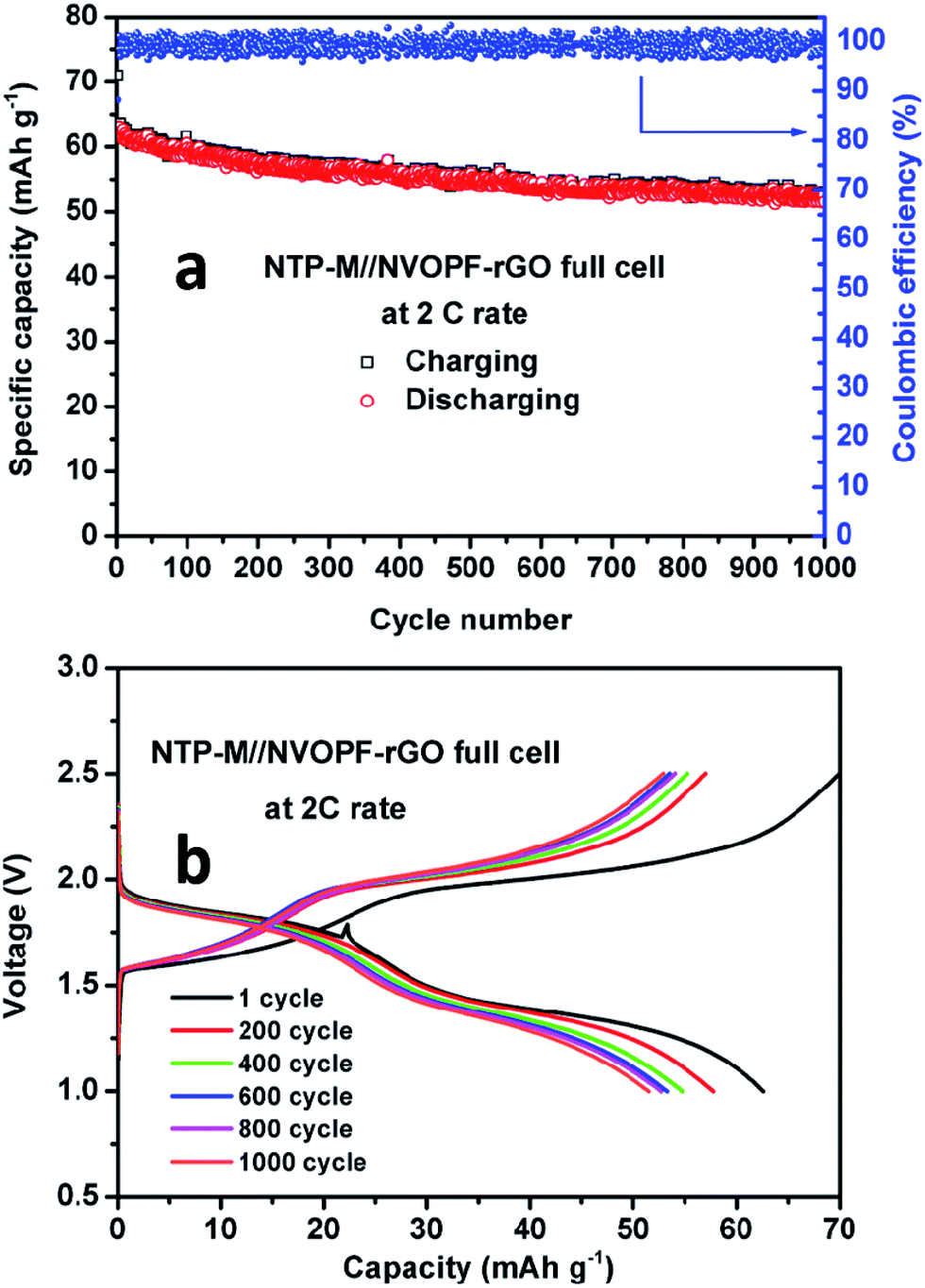
The SEM image and cyclic voltammetry results of the NTP–M sample are shown in Fig. S6.† Furthermore, to confirm the longer cyclability of NTP–M//NVOPF–rGO Na-ion full-cell, we have run this full-cell for 1000 charge–discharge cycles at a 2C (260 mA g−1) rate. The cycling performance and charge–discharge voltage profile plots are shown in Fig. 9. Fig. 9b shows the voltage profiles of the full-cell for 1000 charge and discharge cycles at the 2C rate. This full-cell delivers an initial discharge capacity of 64 mA h g−1 and retains 84% of its initial capacity after 1000 cycles. The high rate capability and excellent cycling performance of the present NTP–M//NVOPF–rGO Na-ion full-cell is mainly attributed to the high-rate electrode materials, which are supported by their structural stability and good electronic conductivity, as well as the highly interactive effect of the CMC binder.
 | ||
| Fig. 9 (a) Cycling performance and (b) charge–discharge cycles of the NTP–M//NVOPF–rGO full-cell for 1000 cycles at a 2C rate. | ||
4. Conclusions
This work reports a stable, high capacity, and high voltage cathode consisting of a Na3V2O2X(PO4)2F3−2X micro-squares–rGO composite synthesized via simple solid state and hydrothermal reactions. The NVOPF–rGO composite with a CMC-Na binder delivered a stable discharge capacity of 108 mA h g−1 with 99% coulombic efficiency, and 98% of the initial discharge capacity was retained after 250 cycles, showing high cyclability. The enhanced electrochemical performance is mainly due to (1) the Na3V2O2X(PO4)2F3−2X micro squares being embedded in rGO, which will increase the electronic conductivity, and (2) interaction between the hydrophilic CMC-Na binder and an active material can facilitate the electron conduction path by maintaining the integrity of the electrode during charge–discharge cycling. Finally, we have demonstrated an NTP–M//NVOPF–rGO full-cell with excellent cyclability, retaining 84% of its initial capacity at 2C after 1000 cycles.Acknowledgements
The authors gratefully acknowledge financial support from the Program to Solve Climate Changes (NRF-2010-C1AAA001-2010-0029031) of Korea (NRF) funded by the Ministry of Science, ICT & Future Planning, Republic of Korea. This research was also supported by the Climate Change Research Hub of KAIST (Grant No. N01170224).References
- Z. Yang, J. Zhang, M. Kintner-Meyer, X. Lu, D. Choi, J. Lemmon and J. Liu, Chem. Rev., 2011, 111, 3577–3613 CrossRef CAS PubMed.
- S. Kim, D. Seo, X. Ma, G. Ceder and K. Kang, Adv. Energy Mater., 2012, 2, 710–721 CrossRef CAS.
- C. Masquelier and L. Croguennec, Chem. Rev., 2013, 113, 6552–6591 CrossRef CAS PubMed.
- C. Deng and S. Zhang, ACS Appl. Mater. Interfaces, 2014, 6, 9111–9117 CAS.
- J. M. Le Meins, M. P. Crosnier-Lopez, A. Hemon-Ribaud and G. Courbion, J. Solid State Chem., 1999, 148, 260–277 CrossRef CAS.
- F. Sauvage, E. Quarez, J. Tarascon and E. Baudrin, Solid State Sci., 2006, 8, 1215–1221 CrossRef CAS.
- R. Shakoor, D. Seo, H. Kim, Y. Park, J. Kim, S. Kim, H. Gwon, S. Lee and K. Kang, J. Mater. Chem., 2012, 22, 20535 RSC.
- M. Xu, L. Wang, X. Zhao, J. Song, H. Xie, Y. Lu and J. Goodenough, Phys. Chem. Chem. Phys., 2013, 15, 13032 RSC.
- P. Moreau, D. Guyomard, J. Gaubicher and F. Boucher, Chem. Mater., 2010, 22, 4126–4128 CrossRef CAS.
- H. Kim, R. Shakoor, C. Park, S. Lim, J. Kim, Y. Jo, W. Cho, K. Miyasaka, R. Kahraman, Y. Jung and J. Choi, Adv. Funct. Mater., 2012, 23, 1147–1155 CrossRef.
- P. Serras, V. Palomares, J. Alonso, N. Sharma, J. López del Amo, P. Kubiak, M. Fdez-Gubieda and T. Rojo, Chem. Mater., 2013, 25, 4917–4925 CrossRef CAS.
- P. Serras, V. Palomares, A. Goñi, I. Gil de Muro, P. Kubiak, L. Lezama and T. Rojo, J. Mater. Chem., 2012, 22, 22301 RSC.
- Y. Park, D. Seo, H. Kim, J. Kim, S. Lee, B. Kim and K. Kang, Adv. Funct. Mater., 2014, 24, 4603–4614 CrossRef CAS.
- P. Kumar, Y. Jung, C. Lim and D. Kim, J. Mater. Chem. A, 2015, 3, 6271–6275 CAS.
- P. Kumar, Y. Jung and D. Kim, J. Solid State Electrochem., 2017, 21, 223–232 CrossRef CAS.
- T. Jaumann, J. Balach, M. Klose, S. Oswald, U. Langklotz, A. Michaelis, J. Eckert and L. Giebeler, Phys. Chem. Chem. Phys., 2015, 17, 24956–24967 RSC.
- A. Magasinski, B. Zdyrko, I. Kovalenko, B. Hertzberg, R. Burtovyy, C. Huebner, T. Fuller, I. Luzinov and G. Yushin, ACS Appl. Mater. Interfaces, 2010, 2, 3004–3010 CAS.
- U. Sen and S. Mitra, ACS Appl. Mater. Interfaces, 2013, 5, 1240–1247 CAS.
- Z. Wang, N. Dupré, A. C. Gaillot, B. Lestriez, B. J. F. Martin, L. Daniel, S. Patoux and D. Guyomard, Electrochim. Acta, 2012, 62, 77–83 CrossRef CAS.
- N. Aarne, E. Kontturi and J. Laine, Cellulose, 2012, 19, 2217–2231 CrossRef CAS.
- U. S. Vogl, P. K. Das, A. Z. Weber, M. Winter, R. Kostecki and S. F. Lux, Langmuir, 2014, 30, 10299–10307 CrossRef CAS PubMed.
- S. L. Chou, Y. Pan, J. Z. Wang, H. K. Liu and S. X. Dou, Phys. Chem. Chem. Phys., 2014, 16, 20347–20359 RSC.
- J. Bridel, T. Azaïs, M. Morcrette, J. Tarascon and D. Larcher, Chem. Mater., 2010, 22, 1229–1241 CrossRef CAS.
- J. Rodríguez-Carvajal, Abstracts of the Satellite Meeting on Powder Diffraction of the XV IUCr Congress, Toulouse, France, 1990, p. 127 Search PubMed.
- A. A. Tsirlin, R. Nath, A. M. Abakumov, Y. Furukawa, D. C. Johnston, M. Hemmida, H.-A. Krug von Nidda, A. Loidl, C. Geibel and H. Rosner, Phys. Rev. B: Condens. Matter Mater. Phys., 2011, 84, 014429–014445 CrossRef.
- Y. U. Park, D. H. Seo, B. Kim, K. P. Hon, H. Kim, S. Lee, R. A. Shakoor, K. Miyasaka, J. M. Tarascon and K. Kang, Sci. Rep., 2012, 2, 704–711 Search PubMed.
- Y. Qi, L. Mu, J. Zhao, Y. S. Hu, H. Liu and S. Dai, Angew. Chem., Int. Ed., 2015, 54, 9911–9916 CrossRef CAS PubMed.
- L. Tang, H. Chang, Y. Liu and J. Li, Adv. Funct. Mater., 2012, 22, 3083–3088 CrossRef CAS.
- V. Di Noto, E. Negro, S. Polizzi, F. Agresti and G. Giffin, ChemSusChem, 2012, 5, 2451–2459 CrossRef CAS PubMed.
- C. Grey and N. Dupré, Chem. Rev., 2004, 104, 4493–4512 CrossRef CAS PubMed.
- T. Yim, S. J. Choi, J. H. Park, W. Cho, Y. N. Jo, T. H. Kim and Y. J. Kim, Phys. Chem. Chem. Phys., 2015, 17, 2388–2393 RSC.
- D. Mazouzi, B. Lestriez, L. Roué and D. Guyomard, Electrochem. Solid-State Lett., 2009, 12, A215 CrossRef CAS.
- Y. Sharma, N. Sharma, G. Subbarao and B. Chowdari, Solid State Ionics, 2008, 179, 587–597 CrossRef CAS.
- W. Wu, J. Yan, A. Wise, A. Rutt and J. Whitacre, J. Electrochem. Soc., 2014, 161, A561–A567 CrossRef CAS.
Footnote |
| † Electronic supplementary information (ESI) available: Raman, NMR, CV, and properties of the NaTi2(PO4)3 sample. See DOI: 10.1039/c7ra01047h |
| This journal is © The Royal Society of Chemistry 2017 |