 Open Access Article
Creative Commons Attribution 3.0 Unported Licence
High-yield colloidal synthesis of monometallic Au nanorod–Au nanoparticle dimers and their application in SERS†
Suli Chen,
Lei Chen,
Huicheng Hu,
Qipeng Liu,
Yong Xu,
Fei Ji,
Feng Bao,
Jian Fan * and
Qiao Zhang
 *
*
Institute of Functional Nano and Soft Materials (FUNSOM), Jiangsu Key Laboratory for Carbon-Based Functional Materials & Devices, Collaborative Innovation Center of Suzhou Nano Science and Technology, SWC for Synchrotron Radiation Research, Soochow University, Suzhou 215123, PR China
First published on 21st February 2017
Abstract
Dimeric nanostructures have attracted much attention owing to their unique structure and excellent physiochemical properties. However, it has been very difficult to make monometallic nanodimers. In this work, we report a simple colloidal approach to synthesize high-yield monometallic Au nanorod–Au nanoparticle dimers by using a negatively charged polyelectrolyte, poly(sodium-p-styrenesulfonate) (PSS), to modify the positively charged Au nanorods. The growth process is studied by systematically tuning the reaction parameters. The as-obtained dimers can serve as a great SERS substrate for the detection of organic molecules because of the existence of “hot-spots”. The analytical enhancement factor (AEF) of the as-prepared dimers is up to 106, which is two magnitudes higher than that of Au nanorods.
Introduction
Over the past decades, dimeric nanostructures, especially noble metal-based nanostructures, have received considerable attention because of their unique structure and the resulting physical and chemical properties as well as their potential applications in diverse fields, such as catalysis,1,2 sensing,3 biological detection,4 and surface-enhanced Raman spectroscopy (SERS).5,6 Since the particular physicochemical properties of dimeric nanostructures are strongly dependent on their morphologies and components,7–9 great efforts have been devoted to synthesizing dimeric nanostructures with controllable morphology and tunable composition.9–15 Among various synthetic approaches developed to date, seed-mediated colloidal synthesis method has proven to be one of the most versatile methods.16,17Many different types of dimeric structures, including metal–metal (Pt–Au,18 Au–Pd,19–21 Pt–Ag, Pd–Ag,22) and metal–oxide (Pt–CdO, Pd–CdO, Au–CdO,23 Au–Fe3O4,24 Ag–Fe3O4 25) have been prepared through the seeded growth approach. Most of the reported examples are based on the heterogeneous nucleation and growth mechanism.26,27 It has been widely accepted that the lattice difference between the two components is critical for the formation of such dimeric structures. When the lattices between two components are very close (usually within 3–5%),28 core–shell nanostructures can be obtained through a continuous epitaxial growth. Larger lattice mismatch will lead to the island growth, in which island-like structure will be formed on the seed surface, resulting in the formation of dimers or multimers.
It is therefore very difficult to make dimeric nanostructures with the same component, such as Au–Au, Ag–Ag and Pt–Pt, or two different components with similar lattice constants, i.e., Au–Ag, where only core–shell structures can be obtained through conventional colloidal seeded growth approaches. Some interesting work has been done to achieve this goal. For instance, Sun and co-worker have developed a seed-mediated, surface-confined asymmetric overgrowth strategy to synthesize high-quality Au–Ag heterodimer.29 Chen group30 and Han group31 have reported that the deposition of Ag or Au onto the pre-existing Au seeds by modifying the seed surface with thiol ligands. Although much progress has been made, the challenge remains. For example, it is difficult to make such dimers in a large scale and cost-effective way because most reported examples involved complex treatment process. In some cases, strong capping ligands, such as thiol, have to be used to modify the surface. However, the strong Au–S bond will hinder the applications of such nanostructures because the surface has been fully occupied by the capping ligands.32 It is thus highly desired to develop a new protocol that can make monometallic nanodimers in a controllable manner.
Herein, we report that a unique dimeric Au nanorod–Au nanoparticle (AuNR–AuNP) nanostructure can be easily obtained through a seed-mediated growth method. Hexadecyltrimethylammonium bromide (CTAB)-capped Au nanorods were first treated with negatively charged poly(sodium-p-styrenesulfonate) (PSS) polyelectrolyte, followed by the reduction of HAuCl4 using tri-sodium citrate (TSC) as the reducing agent.33 Monometallic AuNR–AuNP dimers were successfully prepared in a very high yield (>90%). To figure out the growth mechanism, the growth process has been carefully studied. Additionally, the reaction parameters, including the polyelectrolyte concentration, the pH value, and the addition amount of precursors, have been systematically varied. Based on the experimental results, a plausible growth mechanism has been proposed, in which the existence of negatively charged PSS molecules is believed to be the critical factor. The as-prepared dimers showed great performance in SERS application because of the existence of “hot-spots” in the dimeric structure. The analytical enhancement factor (AEF) of the as-prepared dimers is up to 2.01 × 10⁶, which is much higher than that of Au nanorods.
Experimental
Materials
Hexadecyltrimethylammonium bromide (CTAB, >98.0%) and sodium oleate (NaOL, >97.0%) were purchased from TCI (China). Gold(III) chloride trihydrate (HAuCl4·3H2O, ≥49.0% Au basis), L-ascorbic acid (AA assay: 99.7–100.5%), sodium hydroxide (NaOH, AR, ≥97%), sodium citrate tribasic dehydrate (TSC, ACS reagent, ≥99%), and sodium borohydride (NaBH4, >99%) were purchased from Sigma Aldrich. Poly(sodium-p-styrenesulfonate) (PSS, average Mw ∼ 70![[thin space (1/6-em)]](https://www.rsc.org/images/entities/char_2009.gif) 000), hydrochloric acid (HCl, 37 wt% in water), sodium chloride (NaCl, AR), and silver nitrate (AgNO3, >99%) were purchased from Sinopharm. Ultrapure water with a resistivity of 18.2 MΩ cm was obtained from a Milli-Q system. All glassware was cleaned using aqua regia (VHCl
000), hydrochloric acid (HCl, 37 wt% in water), sodium chloride (NaCl, AR), and silver nitrate (AgNO3, >99%) were purchased from Sinopharm. Ultrapure water with a resistivity of 18.2 MΩ cm was obtained from a Milli-Q system. All glassware was cleaned using aqua regia (VHCl![[thin space (1/6-em)]](https://www.rsc.org/images/entities/char_2009.gif) :
:![[thin space (1/6-em)]](https://www.rsc.org/images/entities/char_2009.gif) VHNO3 = 3
VHNO3 = 3![[thin space (1/6-em)]](https://www.rsc.org/images/entities/char_2009.gif) :
:![[thin space (1/6-em)]](https://www.rsc.org/images/entities/char_2009.gif) 1 ratio), followed by rinsing with copious amounts of ultrapure water. All chemicals were used as received without further treatment.
1 ratio), followed by rinsing with copious amounts of ultrapure water. All chemicals were used as received without further treatment.
Synthesis of AuNRs
AuNRs were prepared according to Ye and co-workers' report, in which a binary surfactant mixture composed of hexadecyltrimethylammonium bromide (CTAB) and sodium oleate (NaOL) was used as the capping ligand.34 In general, the seed solution was freshly prepared as follows: 0.364 g of CTAB was dissolved in 10 mL of ultrapure water in a 20 mL vial. And 0.1 mL of 25.4 mM HAuCl4 was then added. 0.6 mL of fresh 0.01 M NaBH4 was diluted to 1 mL with water and was then quickly injected into the Au(III)–CTAB solution under vigorous stirring (1150 rpm). The solution colour changed from yellow to brownish and the stirring was stopped after 2 min. The seed solution was aged at room temperature for 90 min before use.To prepare the growth solution, 2.1 g (0.037 M in the final growth solution) of CTAB and 0.373 g of NaOL were dissolved in 250 mL of ultrapure water and 6.3 mL of 4 mM AgNO3 solution was added. The mixture was kept undisturbed at 30 °C for 30 min after which 2.945 mL of 25.4 mM HAuCl4 solution was added. The solution colour became colourless after 30 min of stirring (500 rpm). 0.9 mL of HCl (37 wt% in water, 12.1 M) was then introduced to adjust the pH. After another 30 min of slow stirring at 500 rpm, 0.375 mL of 0.064 M ascorbic acid (AA) was added and the solution was vigorously stirred for 30 s. Finally, 0.18 mL of seed solution was injected into the growth solution. The resultant mixture was stirred for 30 s and left undisturbed at 30 °C for 6 h for AuNRs growth. The final products were isolated by centrifugation at 7000 rpm for 10 min followed by removal of the supernatant and then washed once by ultrapure water.
Synthesis of AuNR–AuNP dimers
Positively charged CTAB-capped AuNRs were firstly treated with the negatively charged PSS polymer. In a typical experiment, 5 mL (2.1 mM, counted by gold atomic concentration) of as-prepared CTAB-capped Au NRs dispersion was added to 1 mL of aqueous PSS solution (0.06 g mL−1 with 30 mM NaCl) and stirred overnight. The solution was centrifuged at 7000 rpm for 10 min and redispersed in 5 mL of ultrapure water for use.The as-prepared 5 mL of AuNRs solution was mixed with 0.6 mL of NaOH aqueous solution (24 mM) and 0.3 mL of 5 wt% TSC solution at room temperature for 10 min and in a water bath at 30 °C for 5 min. Subsequently, 0.565 mL of HAuCl4 aqueous solution (25.4 mM) was injected into the solution. This reaction system was kept in a water bath at 30 °C for a designed period without stirring.
Preparation for SERS measurement
The SERS performance of the AuNR–AuNP dimer was tested using R6G as the probe molecule. All the samples were tested on the Si substrate which was plasma-treated before use. Firstly, the AuNR–AuNP dimers were dispersed in Milli-Q water with a concentration around 20 mM and then 10 μL of the colloid AuNR–AuNP dimer solution was dropped onto the Si substrate. After dried, 10 μL of R6G solution with desired concentration (10−4 M, 10−5 M, 10−6 M, and 10−7 M) was distributed onto the Si substrate. The samples were left undisturbed for several hours and washed with ethanol to remove extra R6G molecules.FDTD simulations
The simulation of localized electromagnetic field distributions was performed by a software package, FDTD Solution 8.0. The geometric parameters of the dimer were consistent with TEM images. The length of Au nanorod was set as 103 nm. The diameter of Au nanorod and nanoparticle has been set as 30 nm and 18 nm, respectively, during simulation. Laser excitation wavelength was 805 nm for the dimer. The refractive index of Milli-Q water was taken to be 1.0 as background. The dielectric permittivity of gold was taken from previous reported work.35 In this work, it should be noticed that a circularly polarized electromagnetic plane wave was launched to simulate the light interacting with the nanostructures. Furthermore, the simulation regions were divided into meshes of 0.5 nm in size.Characterization
Transmission electron microscopy (TEM) characterization was conducted by using a LaB6 TEM (TECNAI G2, FEI), operating at 200 kV. High resolution transmission electron microscope (HRTEM) images were obtained at 200 kV by using the TECNAI G2 F20 from FEI, USA. All the samples are centrifuged and washed with water twice before dropping it onto the TEM grid. The UV-vis spectra were obtained by using the LAMBDA 750 spectrograph (PERKINELMER, USA) in a range of 300–1000 nm.Results and discussion
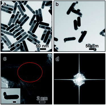
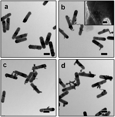
The dimeric AuNR–AuNP nanoparticles were obtained through a seed-mediated growth process. As shown in Fig. 1a, the diameter and length of the as-obtained AuNRs are 24 nm and 103 nm, respectively. The prepared AuNRs are positively charged with a surface charge of +29.2 mV because of the existence of excessive CTAB (Fig. S1†). To induce the anisotropic growth of Au nanoparticles, the positively charged AuNRs were treated with negatively charged PSS polyelectrolyte solution and then used as the seed. After surface treatment, the surface charge became −16.4 mV, indicating the successful surface modification (Fig. S1†). The as-prepared AuNRs solution was then mixed with NaOH aqueous solution and tri-sodium citrate (TSC) solution and kept in a water bath at 30 °C. Subsequently, HAuCl4 aqueous solution was injected into the mixture and kept at 30 °C for 3 hours without stirring. Fig. 1b shows the TEM image of the product, from which one can clearly see that dimeric AuNR–AuNP nanostructures were formed. It is worth pointing out that most dimers consist of one nanorod and one Au nanoparticle. The Au nanoparticle has a relatively broad size distribution from ∼6 nm to ∼20 nm. Meanwhile, the diameter of Au nanorods increased to ∼30 nm. As shown in Fig. 1b, AuNR and AuNP were directly-fused together, which is hardly achievable with reported methods, where two nanocrystals were linked through functionalized ligands. As shown in Fig. 1c, rich defects can be observed at the interface between the AuNR and AuNP. The FFT diffractogram corresponding to the red circle in Fig. 1c also confirmed the rich defects at the interface.To investigate the growth mechanism of AuNR–AuNP dimers, the evolution process has been carefully monitored by taking aliquots out from the reaction solution at different reaction stages. As shown in Fig. 2a, the smooth surface become very rough after reacted for 15 min as some rugged Au bumps can be observed on the surface of AuNRs. Both the HR-TEM image and the corresponding FFT diffractogram (Fig. S2†) confirmed the existence of rich defects. When the reaction time was prolonged to 30 min, a long tail (up to 35 nm) can be seen on each nanorod and some bumps are still existing (Fig. 2b). The stacking faults can be clearly observed in the HR-TEM image (the inset in Fig. 2b) when the interface between the tail and the nanorod was enlarged. The long and thin tail became shorter and fatter gradually with prolonged reaction time, as shown Fig. 2c and d. It is worth pointing out that the surface gradually became smooth again after reacted for 1 hour. With the disappearance of some bumps, the diameter of AuNRs increased gradually to 30 nm eventually.
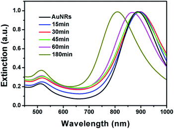
It is well known that the surface plasmon resonance (SPR) properties of Au nanoparticles are highly dependent on their morphologies. The morphological change has significant impact on their SPR properties. As shown in Fig. 3, the original AuNRs have a sharp extinction peak at 890 nm, which red shifted to around 896 nm after reacted for 15 min. The slight red-shift might be attributed to the growth of small bumps on the tip that make higher aspect ratio of the AuNRs. Although long tails have been observed when the system was kept for 30 min, no much red-shift has been observed. The SPR peak slightly red shifted to about 898 nm, which might be ascribed to the fact that the products are branched nanostructures rather than straight nanorods. With the shorter and fatter branch nanostructures, the extinction peak blue-shifted significantly. As depicted in Fig. 3, the final product has an extinction peak at 805 nm, which is in good agreement with its lower aspect ratio. It is worth pointing out that no sharp peak at ∼520 nm has been observed during the whole process, implying that no free gold nanoparticles have been formed in the solution.
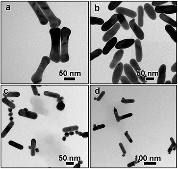
To further figure out the growth mechanisms of the monometallic dimers, a series of experiments have been carried out. The influence of PSS polyelectrolyte was examined first. Without the PSS treatment, a “dog-bone” shaped nanostructure can be obtained, as depicted in Fig. 4a. These phenomena can be explained by the fact that the density of CTAB bilayer at the end is lower than that on the side because the curvature of the end is larger than that at the side surface.36 As a result, Au atoms nucleated and grew preferentially at the end of AuNR seeds, leading to the formation of “dog-bone” shaped nanoparticles.37–39 Rich stacking defects have also been observed in the TEM image (Fig. S3a†). When AuNRs were first treated with low concentration of PSS solution (3 mg mL−1 in the final solution), only irregular nanorods can be obtained and the dog-bone shaped nanostructures disappeared (Fig. 3b), suggesting the important role of PSS treatment. Dimeric AuNR–AuNP can be obtained when the AuNRs were treated with higher PSS concentration (10 mg mL−1, Fig. 1b). Further increasing the PSS concentration to 20 mg mL−1 led to the formation of free Au nanoparticles, while no dimeric nanostructures can be observed (data not shown). Higher coverage of PSS on the AuNRs surface might inhibit the deposition of Au atoms, resulting in the formation of free Au nanoparticles. From the above results, we can conclude that the PSS treatment is critical to the formation of dimeric nanostructures.
It is widely accepted that the reaction kinetics plays an important role in the seeded growth process. In general, slow reaction rate favours the seeded growth as self-nucleation process will be eliminated and less free secondary nanoparticles will be formed. In this work, the reaction kinetics can be controlled by several factors, such as pH, temperature, reducing agent, and the concentration of precursors. The role of pH was studied carefully. The concentration of NaOH was applied to tune pH of solution. It was reported that the reduction potential of Au(III) complexes was strongly related to the pH of solution. The highly reactive [AuCl3(OH)]− complex can be converted to less reactive [AuCl2(OH)2]− and [AuCl(OH)3]− species when the pH value was higher than about 6.2, leading to lower reactivity upon increasing pH.40 In the absence of NaOH, the pH value is around 5.5. The solution became reddish quickly, suggesting the formation of free Au nanoparticles, which has been confirmed by the TEM characterization. As shown in Fig. 4c, although some dimeric nanostructures can still be obtained, large amount of free Au nanoparticles can be observed. When the NaOH concentration was increased to 1.0 mM, no red or purple colour has been observed and the colour change slowly, suggesting no free Au nanoparticles were formed. The pH value was around 7.9. Dimeric AuNR–AuNP nanostructures can be prepared under this condition (Fig. 4d), confirming that higher pH value favours the formation of dimers.
The addition amount of HAuCl4 solution also plays an important role in determining the final morphology of product. We varied the addition amount of HAuCl4 solution and kept the other parameters being constant. As shown in Fig. 5a, when the molar ratio of HAuCl4 and AuNRs was 0.7![[thin space (1/6-em)]](https://www.rsc.org/images/entities/char_2009.gif) :
:![[thin space (1/6-em)]](https://www.rsc.org/images/entities/char_2009.gif) 1, a long tail can be observed on the surface of each AuNR after kept at 30 °C for 3 hours, which is like the intermediate shown in Fig. 2b. Correspondingly, the extinction peak red-shifted to 903 nm (Fig. 5d). When more gold precursor was added, the long tail disappeared and a branch-like structure can be obtained. The corresponding extinction peak blue shifted to 835 nm. Further increasing the molar ratio between HAuCl4 and AuNRs to 1.75
1, a long tail can be observed on the surface of each AuNR after kept at 30 °C for 3 hours, which is like the intermediate shown in Fig. 2b. Correspondingly, the extinction peak red-shifted to 903 nm (Fig. 5d). When more gold precursor was added, the long tail disappeared and a branch-like structure can be obtained. The corresponding extinction peak blue shifted to 835 nm. Further increasing the molar ratio between HAuCl4 and AuNRs to 1.75![[thin space (1/6-em)]](https://www.rsc.org/images/entities/char_2009.gif) :
:![[thin space (1/6-em)]](https://www.rsc.org/images/entities/char_2009.gif) 1 led to the formation of free Au nanoparticles, as confirmed by both the TEM characterization (Fig. 5c) and the sharp extinction peak at ∼520 nm (Fig. 5d).
1 led to the formation of free Au nanoparticles, as confirmed by both the TEM characterization (Fig. 5c) and the sharp extinction peak at ∼520 nm (Fig. 5d).
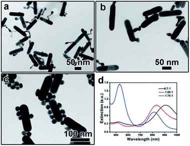 | ||
Fig. 5 (a–c) TEM images showing the product obtained by tuning the molar ratio of HAuCl4 and AuNRs: (a) 0.7![[thin space (1/6-em)]](https://www.rsc.org/images/entities/char_2009.gif) : :![[thin space (1/6-em)]](https://www.rsc.org/images/entities/char_2009.gif) 1, (b) 1.05 1, (b) 1.05![[thin space (1/6-em)]](https://www.rsc.org/images/entities/char_2009.gif) : :![[thin space (1/6-em)]](https://www.rsc.org/images/entities/char_2009.gif) 1, (c) 1.75 1, (c) 1.75![[thin space (1/6-em)]](https://www.rsc.org/images/entities/char_2009.gif) : :![[thin space (1/6-em)]](https://www.rsc.org/images/entities/char_2009.gif) 1; (d) UV-vis spectra corresponding to (a–c). 1; (d) UV-vis spectra corresponding to (a–c). | ||
Based on the above results, a plausible growth mechanism has been proposed. Since the surface of AuNRs is covered with CTAB bilayers, the original AuNRs were positively charged. After repeating washing and additional treatment using negatively charged PSS solution, the surface became negatively charged because of both the weak binding between CTAB bilayer and Au surface and the long chain of PSS polyelectrolyte. The negatively charged surface as well as the polyelectrolyte is critical for the following anisotropic deposition of Au atoms. When PSS chain partially wrapped AuNR surface, the negative charged long chain repelled the deposition of negatively charged Au atoms, which can be confirmed by the fact that free Au nanoparticles were formed and no dimeric nanostructures could be obtained when the PSS concentration was increased to 20 mg mL−1. After treated with low concentration of PSS solution, the AuNR surface was partially wrapped, leaving some parts available for Au atom deposition. As a result, a lot of rugged bumps can be observed after reacted for 15 min (Fig. 2a). When more Au atoms were reduced, some small bumps can grow anisotropically to form long tails, as shown in Fig. 2b. The anisotropic growth might be attributed to the existence of PSS polyelectrolyte and the resulted defects. However, the thin and long tail is not thermodynamically stable because of the high surface energy. To minimize the surface energy, the long tail might go through an Ostwald ripening process, leading to the formation of branched and eventually the spherical shaped nanoparticles. The reaction kinetics is important in the formation of monometallic nanodimers. High pH value and low concentration of Au precursor can slow down the reaction rate, favouring the formation of AuNR–AuNP dimers.
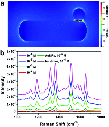
It was well known that dimers can possess superior SERS performance to single particles because of the existence of “hot-spots” formed between two adjacent nanoparticles.41–45 The finite-difference time-domain (FDTD) method has been applied to understand the possible enhancement mechanism in the dimeric nanostructure. As shown in Fig. 6a, a clear enhancement in the interface region has been observed, implying the potential application of such nanoparticles in SERS. This simulation results have been further confirmed by the experimental results. In this work, Rhodamine 6G (R6G) molecules were used as the target molecules. As shown in Fig. 6b (black line), no signal could be detected when naked silicon wafer was used as the substrate ([R6G] = 10−4 M). When Au nanorods were used as the substrate, characteristic peaks of R6G could be observed, confirming the enhancement of Au nanoparticles. When the as prepared AuNR–AuNP dimers were used as the substrate, significant enhancement of the intensity could be observed. It should be noted that the amount of AuNRs and the dimers were kept the same. The detection limit of R6G by using the AuNR–AuNP dimers is around 10−7 M. The analytical enhancement factor (AEF) of the as-prepared dimers is about 2.01 × 10⁶, which is two magnitudes higher than that of Au nanorods (∼1.6 × 10⁴). It is worth noting that although the dimers show much better SERS performance than single Au nanorods, the AEF of the as-prepared dimers is still lower than some of the best results reported by the literature. For example, Hakonen and co-workers reported an AEF up to 1011 by using dimer-on-mirror gold nanostructures as the substrates.44 This result might be attributed to the fact that the density of “hot-spots” in the obtained dimer structure is not so high as that in the reported results. Since our synthetic approach is much simpler than many reported lithography method, it is believed that this method can be used to prepare highly efficient SERS substrate by modifying the structure and composition. More research efforts are being devoted to optimizing the dimeric structure and to improving its SERS performance.
Conclusions
In summary, monometallic AuNR–AuNP dimers have been successfully prepared via a simple colloidal approach. The reaction parameters, such as the reaction time, PSS concentration, pH value, and precursor amount, have been systematically tuned to study the growth process. A plausible growth mechanism has been proposed, in which the surface treatment with negatively charged polyelectrolyte is believed to be critical to the formation of dimeric nanostructures. The as-obtained dimers can serve as a great SERS substrate for the detection of organic molecules because of the existence of “hot spots”. This simple synthesis approach may provide a potential direction for the synthesis of different shaped Au dimers by using other shaped Au nanocrystal as seeds. This research is important because it not only point out a new direction for the preparation of monometallic dimeric nanostructure, but also help to promote the applications of nanomaterials.Acknowledgements
This work was supported by the National Natural Science Foundation of China (21401135, 21673150, 21472135) and the Natural Science Foundation of Jiangsu Province (BK20140304, BK20151216). This project is funded by the Priority Academic Program Development of Jiangsu Higher Education Institutions (PAPD).Notes and references
- C. Wang, H. F. Yin, S. Dai and S. H. Sun, Chem. Mater., 2010, 22, 3277–3282 CrossRef CAS.
- X. Wang, G. Li, T. Chen, M. Yang, Z. Zhang, T. Wu and H. Chen, Nano Lett., 2008, 8, 2643–2647 CrossRef CAS PubMed.
- Y. Cheng, M. Wang, G. Borghs and H. Chen, Langmuir, 2011, 27, 7884–7891 CrossRef CAS PubMed.
- J. S. Choi, Y. W. Jun, S. I. Yeon, H. C. Kim, J. S. Shin and J. Cheon, J. Am. Chem. Soc., 2006, 128, 15982–15983 CrossRef CAS PubMed.
- G. Chen, Y. Wang, M. Yang, J. Xu, S. J. Goh, M. Pan and H. Chen, J. Am. Chem. Soc., 2010, 132, 3644–3645 CrossRef CAS PubMed.
- M. Ringler, T. A. Klar, A. Schwemer, A. S. Susha, J. Stehr, G. Raschke, S. Funk, M. Borowski, A. Nichtl, K. Kurzinger, R. T. Phillips and J. Feldmann, Nano Lett., 2007, 7, 2753–2757 CrossRef CAS PubMed.
- K. D. Gilroy, A. Ruditskiy, H.-C. Peng, D. Qin and Y. Xia, Chem. Rev., 2016, 114, 10412–10472 Search PubMed.
- X. Song, X. Zhang and P. Yang, RSC Adv., 2016, 6, 107433–107441 RSC.
- Y. Sun, Natl. Sci. Rev., 2015, 2, 329–348 CrossRef.
- B. Ni and X. Wang, CrystEngComm, 2015, 17, 6796–6808 RSC.
- Y. Liu and Y. Sun, Nanoscale, 2015, 7, 13687–13693 RSC.
- Z. Aabdin, J. Y. Lu, X. Zhu, U. Anand, N. D. Loh, H. B. Su and U. Mirsaidov, Nano Lett., 2014, 14, 6639–6643 CrossRef CAS PubMed.
- R. Sardar, T. B. Heap and J. S. Shumaker-Parry, J. Am. Chem. Soc., 2007, 129, 5356–5357 CrossRef CAS PubMed.
- W. Li, P. H. Camargo, L. Au, Q. Zhang, M. Rycenga and Y. Xia, Angew. Chem., 2010, 49, 164–168 CrossRef CAS PubMed.
- H. Hu, F. Ji, Y. Xu, J. Yu, Q. Liu, L. Chen, Q. Chen, P. Wen, Y. Lifshitz, Y. Wang, Q. Zhang and S. T. Lee, ACS Nano, 2016, 10, 7323–7330 CrossRef CAS PubMed.
- C. Gao, J. Goebl and Y. Yin, J. Mater. Chem. C, 2013, 1, 3898 RSC.
- Y. Xia, X. Xia and H. C. Peng, J. Am. Chem. Soc., 2015, 137, 7947–7966 CrossRef CAS PubMed.
- C. A. Garcia-Negrete, B. R. Knappett, F. P. Schmidt, T. C. Rojas, A. E. H. Wheatley, F. Hofer and A. Fernandez, RSC Adv., 2015, 5, 55262–55268 RSC.
- C. C. Crane, J. Tao, F. Wang, Y. Zhu and J. Chen, J. Phys. Chem. C, 2014, 118, 28134–28142 CAS.
- B. Lim, H. Kobayashi, T. Yu, J. Wang, M. J. Kim, Z.-Y. Li, M. Rycenga and Y. Xia, J. Am. Chem. Soc., 2010, 132, 2506–2507 CrossRef CAS PubMed.
- S. E. Habas, H. Lee, V. Radmilovic, G. A. Somorjai and P. Yang, Nat. Mater., 2007, 6, 692–697 CrossRef CAS PubMed.
- S. U. Lee, J. W. Hong, S. I. Choi and S. W. Han, J. Am. Chem. Soc., 2014, 136, 5221–5224 CrossRef CAS PubMed.
- X. Ye, D. Reifsnyder Hickey, J. Fei, B. T. Diroll, T. Paik, J. Chen and C. B. Murray, J. Am. Chem. Soc., 2014, 136, 5106–5115 CrossRef CAS PubMed.
- H. Yu, M. Chen, P. M. Rice, S. X. Wang, R. L. White and S. H. Sun, Nano Lett., 2005, 5, 379–382 CrossRef CAS PubMed.
- L. Zhang, Y. H. Dou and H. C. Gu, J. Colloid Interface Sci., 2006, 297, 660–664 CrossRef CAS PubMed.
- M. Casavola, R. Buonsanti, G. Caputo and P. D. Cozzoli, Eur. J. Inorg. Chem., 2008, 837–854 CrossRef CAS.
- L. Carbone and P. D. Cozzoli, Nano Today, 2010, 5, 449–493 CrossRef CAS.
- F.-R. Fan, D.-Y. Liu, Y.-F. Wu, S. Duan, Z.-X. Xie, Z.-Y. Jiang and Z.-Q. Tian, J. Am. Chem. Soc., 2008, 130, 6949–6951 CrossRef CAS PubMed.
- Y. Hu, Y. Liu, Z. Li and Y. Sun, Adv. Funct. Mater., 2014, 24, 2828–2836 CrossRef CAS.
- Y. Feng, J. He, H. Wang, Y. Y. Tay, H. Sun, L. Zhu and H. Chen, J. Am. Chem. Soc., 2012, 134, 2004–2007 CrossRef CAS PubMed.
- J. Huang, Y. Zhu, C. Liu, Z. Shi, A. Fratalocchi and Y. Han, Nano Lett., 2016, 16, 617–623 CrossRef CAS PubMed.
- M. Watari, R. A. McKendry, M. Vogtli, G. Aeppli, Y. A. Soh, X. Shi, G. Xiong, X. Huang, R. Harder and I. K. Robinson, Nat. Mater., 2011, 10, 862–866 CrossRef CAS PubMed.
- M. A. H. Muhammed, M. Doeblinger and J. Rodriguez-Fernandez, J. Am. Chem. Soc., 2015, 137, 11666–11677 CrossRef CAS PubMed.
- X. Ye, C. Zheng, J. Chen, Y. Gao and C. B. Murray, Nano Lett., 2013, 13, 765–771 CrossRef CAS PubMed.
- E. D. Palik, Handbook of Optical Constants of Solids, Academic Press, 1997, vol. 1 Search PubMed.
- F. Wang, S. Cheng, Z. Bao and J. Wang, Angew. Chem., Int. Ed., 2013, 52, 10344–10348 CrossRef CAS PubMed.
- F. Ratto, P. Matteini, F. Rossi and R. Pini, J. Nanopart. Res., 2009, 12, 2029–2036 CrossRef.
- X. Xu and M. B. Cortie, Adv. Funct. Mater., 2006, 16, 2170–2176 CrossRef CAS.
- J. H. Song, F. Kim, D. Kim and P. Yang, Chem.–Eur. J., 2005, 11, 910–916 CrossRef CAS PubMed.
- X. Ji, X. Song and J. Li, J. Am. Chem. Soc., 2007, 129, 13939–13948 CrossRef CAS PubMed.
- P. H. C. Camargo, M. Rycenga, L. Au and Y. N. Xia, Angew. Chem., Int. Ed., 2009, 48, 2180–2184 CrossRef CAS PubMed.
- C. E. Talley, J. B. Jackson, C. Oubre, N. K. Grady, C. W. Hollars, S. M. Lane, T. R. Huser, P. Nordlander and N. J. Halas, Nano Lett., 2005, 5, 1569–1574 CrossRef CAS PubMed.
- J. P. Camden, J. A. Dieringer, Y. M. Wang, D. J. Masiello, L. D. Marks, G. C. Schatz and R. P. Van Duyne, J. Am. Chem. Soc., 2008, 130, 12616–12617 CrossRef CAS PubMed.
- A. Hakonen, M. Svedendahl, R. Ogier, Z. Yang and M. Käll, Nanoscale, 2015, 7, 9405–9410 RSC.
- H. Xu and M. Käll, Phys. Rev. Lett., 2002, 89, 246802 CrossRef PubMed.
Footnote |
| † Electronic supplementary information (ESI) available: Experimental details and additional TEM image. See DOI: 10.1039/c7ra01039g |
| This journal is © The Royal Society of Chemistry 2017 |

