
 Open Access Article
 This Open Access Article is licensed under a Creative Commons Attribution-Non Commercial 3.0 Unported Licence
Collective generation of milliemulsions by step-emulsification†
Xing Huanga,
Max Eggersdorferb,
Jinrong Wub,
Chun-Xia Zhaoc,
Zhongbin Xu *ab,
Dong Chen*abd and
David A. Weitz*b
*ab,
Dong Chen*abd and
David A. Weitz*b
aInstitute of Process Equipment, College of Energy Engineering, Zhejiang University, Zheda Road No. 38, Hangzhou, 310027, China. E-mail: xuzhongbin@zju.edu.cn; chen_dong@zju.edu.cn
bJohn A. Paulson School of Engineering and Applied Sciences, Harvard University, Cambridge, Massachusetts 02138, USA. E-mail: weitz@seas.harvard.edu
cAustralian Institute for Bioengineering and Nanotechnology, The University of Queensland, St Lucia, QLD, Australia 4072
dState Key Laboratory of Fluid Power and Mechatronic Systems, Zhejiang University, Zheda Road No. 38, Hangzhou, 310027, China
First published on 7th March 2017
Abstract
Emulsification is a key step in many processes for the production and functionalization of dispersed liquid systems. Here, we report a versatile and robust device that generates monodisperse milliemulsions by step-emulsification. In contrast to the conventional design in which each channel is physically separated, we use a shallow plateau sandwiched between two parallel glass strips to connect all channels in a microcapillary film (MCF) before emerging in a deep reservoir. Because of the open plateau that connects different channels, the flow tips from neighboring channels may get immediately in contact with each other; this interaction may lead to the relative movement and deformation of the flow tips, to repulsion or even coalescence, enabling droplet generations from different channels to synchronize. By simply tuning the interaction, we achieve Janus droplets, drops of fluids mixed at different ratios and mixed drops of different compositions. The in situ generation of droplets with excellent control is essential for various applications.
Introduction
Fine emulsions with controlled droplet size and composition is critical for chemical synthesis and production of components in pharmaceuticals, cosmetics or foods.1–3 Techniques generating monodisperse droplets mainly include T-junctions,4 flow focusing,5 and step-emulsification.6 In a T-junction device, the dispersed phase is sheared off by the continuous phase at a junction perpendicular to the dispersed phase, while in a flow focusing device, the continuous phase co-flows with the dispersed phase and is focused to shear the dispersed phase into a thin thread, which ruptures via Rayleigh–Plateau instability. The step-emulsification, discovered about 20 years ago,7 is a low shear method by virtue of the spontaneous breakup of a quasi-two-dimensional liquid stream at an abrupt widening of the channel. A step-emulsification device usually combines a shallow channel and an abrupt (step-like) opening to a deep and wide reservoir.8 Within the device, a dispersed phase is pushed into the shallow channel and the inflated flow tip grows radially outwards. When the flow tip enters the wide reservoir, it is no longer confined and expands in three dimensions, reducing its Laplace pressure. The difference in Laplace pressure between the dispersed phase in the shallow channel and in the deep reservoir induces a flow that rapidly depletes the dispersed phase from the shallow channel. A neck forms between the tip and the dispersed phase in the channel that breaks via a Rayleigh–Plateau instability.9,10 Drops produced by step-emulsification are exceptionally monodisperse. The size of the drops barely depends on the flow rates of the dispersed and continuous phases below a critical capillary number and is mainly determined by the geometry of the device, such as the width and height of the shallow channel.11Compared with T-junction and flow focusing, step-emulsification provides excellent monodispersity, scalable production frequency, the possibility to produce emulsions with high volume fraction of the dispersed phase, low energy consumption with low shear stress, suitable for shear sensitive components, and simple handling of the device.12–14 In addition, combining step-emulsification with the classical flow-focusing junction, people have achieved nanodrops with a well calibrated size15 and double emulsions with an ultra-thin shell.16 Step-emulsification has also been used to synchronize two individual production channels to produce pairs of different droplets with a well-defined volume for controlled bio-chemical reactions17 or been developed as equivalents of membrane emulsification to achieve high throughput of monodisperse emulsions.18,19 Nevertheless, the advantage of step-emulsification has not fully been explored yet.
Here, we demonstrate a facile design to manipulate the droplets that are produced by step-emulsification via the interactions between neighboring production channels. To achieve this, we add a shallow plateau at the end of a microcapillary film (MCF) that contains an array of hollow capillaries embedded in a plastic film.20,21 The shallow plateau, therefore, connects all channels and it is found to synchronize the droplet production of different channels through the interactions of flow tips within the plateau. The device allows the high-throughput generation of monodisperse droplets with easily adjustable volume, production rate and composition.
Materials and methods
The microcapillary film (MCF) is fabricated by polymer extrusion. The shallow plateau at the end of MCF is created by two parallel glass strips. The height of the plateau is h ∼ 300 μm and the width is L ∼ 1.4 mm. The surface of the device is treated using Aquapel (PPG Industries) that renders it hydrophobic. The whole device is submerged in a silicon oil reservoir. A picture of the setup is shown in Fig. 1a. The dispersed phase is DI water. The continuous phase is silicone oil (20 cSt, Gelest) with 5 wt% Dow Corning 749 (Dow Corning). The surface tension is 8.0 mN m−1. The dispersed phase is injected by syringe pumps (Harvard Apparatus) into individual channels and flows through the shallow plateau into the oil reservoir. The oil reservoir is stationary and gravity slowly carries the drops to the bottom of the container, as water is heavier than the silicone oil. Drop formation is monitored with a camera. We measure the drop size using image analysis software (ImageJ).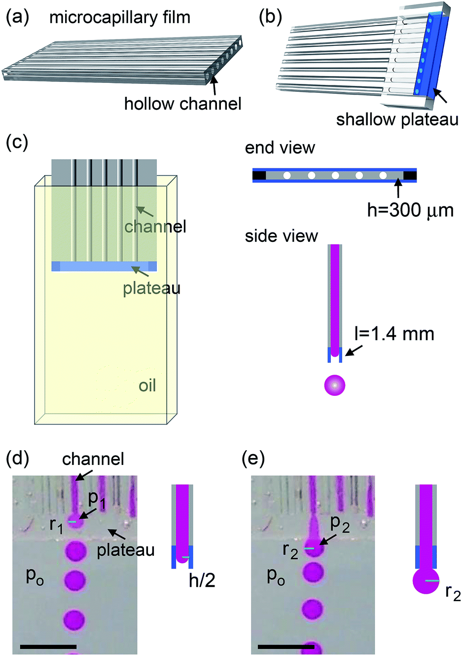 | ||
| Fig. 1 Millifluidic device fabricated using a microcapillary film. Schematic drawing of (a) the microcapillary film, (b) the device and (c) the experimental setup. The millifluidic device consists of a microcapillary film between two parallel glasses at the end, which are colored blue. The parallel glasses create a plateau of height h ∼ 300 μm and width l ∼ 1.4 mm and generate millidrops by step-emulsification. (d) When the fluid comes in, the plateau squeezes the fluid tip into a flat pancake with radius r1 and height h. (e) When the fluid exists the plateau, the fluid tip forms a spherical shape with radius r2. Laplace pressure, therefore, drives the formation of monodisperse droplets. The scale bars are 3 mm in (d) and (e). | ||
Experiments and discussions
The microcapillary film (MCF) is consisted of an array of parallel hollow channels embedded in a thin plastic film (Fig. 1a) and is fabricated by polymer melt extrusion within a slit die with a gas-entrainment assembly that has a row of hollow needles.22 To fabricate the step-emulsification device, two parallel glass strips are attached at the end of a MCF, which create a shallow plateau, as shown in Fig. 1b. The shallow plateau confines the fluids injected from individual channels in quasi-two dimensions before they enter the wide reservoir. There are no walls that separate individual channels within the shallow plateau; therefore, the fluids from neighboring channels can interact within the shallow plateau. The device is submerged in a stationary oil reservoir and water is pumped through the microcapillary channel into the oil phase, as shown in Fig. 1c. We first run the device as a single drop generator. The dispersed phase is confined in a shallow plateau when it exits the microcapillary channel and expands radially outwards within the plateau, forming a pancake-like shape. Assuming equilibrium conditions, the internal pressure of the flow tip is p1 = γ(2/h + 1/r1), where γ is the surface tension, h is the height of the plateau and r1 is the radius of the flow tip, as shown in Fig. 1d. Because h is much smaller than r1, the pressure is approximated as p1 ∼ 2γ/h. As r1 increases in size, p1 remains roughly the same. When the flow tip enters the oil reservoir, the horizontal confinement is released and the internal pressure due to the interfacial curvature suddenly drops to p2 ∼ 2γ/r2, where r2 is the radius of the flow tip, as shown in Fig. 1e. Because h ≪ r2, p1 ≫ p2; the pressure difference quickly drives the dispersed phase from the shallow plateau into the oil reservoir, forming a neck in the plateau that eventually breaks up. Gravity then slowly carries the droplets to the bottom and the step-emulsification process repeats periodically at frequency f. The motion of the continuous fluid within the plateau during the step-emulsification process is directly visualized through an air bubble stuck in the plateau that moves synchronously back and forth as the flow tip grows and breaks into drops, as shown in Fig. S1.†The droplets generated by the device are monodisperse with d ∼ 1.14 ± 0.06 mm, as shown in Fig. 2d. Though the droplets are relatively large and water (ρwater = 1 g cm−3) is denser than oil (ρoil = 0.95 g cm−3), gravity is not the main force that leads to the droplet breakup, as evidenced by the spherical shape of the droplet right before breakup (Fig. 2a). Consistent with step-emulsification, two distinct regimes occurs depending on the flow rate of the dispersed phase. When the flow rate is below a critical value, the size of the drops barely changes as the flow rate of the dispersed phase increases, as shown in Fig. S2.† This regime is usually called “dripping regime”. When the flow rate increases above the critical value, step-emulsification transitions to a second regime which is usually named “continuous outflow regime”;23 the droplet remains monodisperse but the size jumps to a much larger value of d ∼ 4.0 mm. The critical flow rate is 58 mL h−1, corresponding to a critical capillary number of 0.042, which is consistent with the critical capillary number reported previously.24 In the continuous outflow regime, the breakup is no longer dominated by Laplace pressure; gravity also plays an important role, as suggested by the non-spherical shape of the drop before pinch-off, as shown in Fig. S2.† Below, we will focus on the collective generation of droplets through the interactions between neighboring channels in the dripping regime.
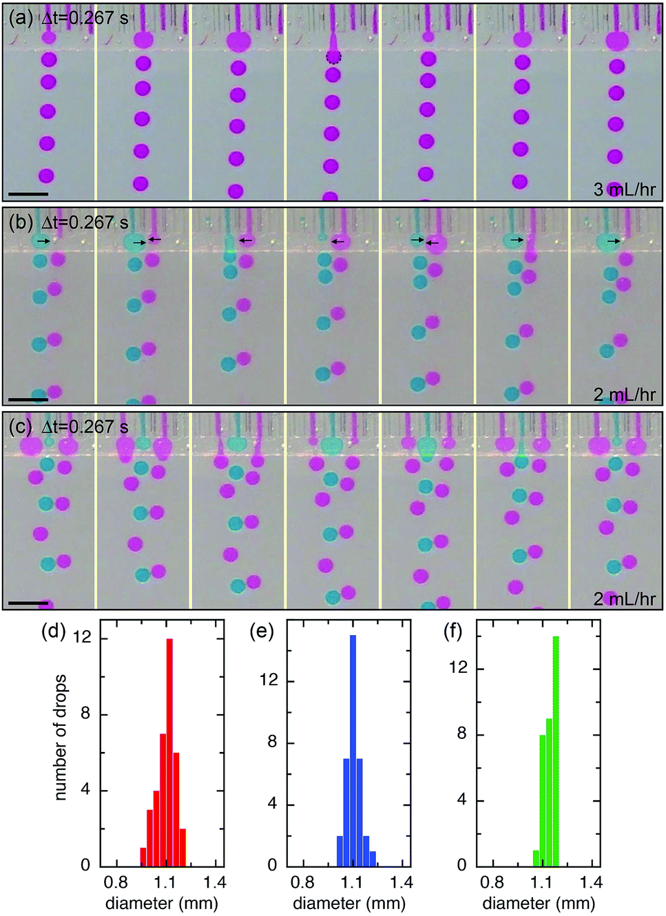 | ||
| Fig. 2 Time sequences of optical images showing the formation of monodisperse droplet by step-emulsification of (a) a single channel, (b) two channels and (c) three channels. Collective generations of milliemulsions are observed in two channels and three channels due to the interaction between neighboring channels. The black arrows in (b) suggest the expanding directions of the flow tips within the shallow plateau. (d), (e) and (f) Size distribution of droplets generated in (a), (b) and (c), respectively. The average size of drop is d ∼ 1.14 mm ± 0.06 mm. For better visibility, the red fluid is dyed with sulfur rhodomine B and the green fluid with Nile blue. The scale bars are 3 mm in (a)–(c). | ||
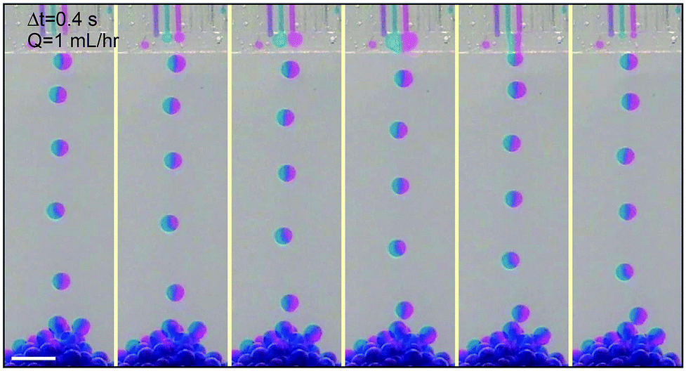
We extend the use of the device from a single channel to multiple channels; each channel retains all relevant properties of a single step-emulsification unit and is connected through the joint shallow plateau. The synchronization of drop generation between two neighboring channels is achieved by a cross talk of the flow tips within the shallow plateau. For example, in the case of two neighboring channels running simultaneously, the flow tip of the left channel expands radially outward in two dimensions when it reaches the plateau, expelling the fluid next to it. Subsequently, the fluid from the right channel reaches the plateau and also expands within the plateau, pushing the left flow tip into the oil reservoir. When the left flow tip enters the reservoir, its Laplace pressure changes rapidly and the fluid is quickly retracted from the plateau into the reservoir; this, in turn, aids the expansion of the right flow tip within the plateau, as the volume of the left fluid shrinks quickly and pulls neighboring fluid inward. When a droplet is pinched off from the left channel, a new flow tip emerges and expands within the plateau, expelling the right flow tip. Next, a droplet will be formed from the right channel, and the cycle is repeated, resulting in an alternating droplet production, as shown in Fig. 2b. When the number of channels increases to three or more, the productions of droplets are synchronized; even-numbered channels generate drops at the same time while odd-numbered channels generate drops between the intervals, as shown in Fig. 2c and S3.† The synchronized motion of multiple channels generates monodisperse droplets with a narrow size distribution, as shown in Fig. 2e and f. The collective motion maintains at high flow rates, up to Q = 54 mL h−1 of each channel. The size and dispersity of drops generated by the collective motion is comparable to that of a single emulsifier but at a much higher throughput, as shown in Movie S1.†
The interactions of the flow tips within the shallow plateau may lead to relative movement and deformation of the interfaces, to repulsing or coalescence of the droplets, respectively; therefore, droplets can be manipulated through these interactions. When neighboring channels are infused with the same volumetric flow rate (QL = QR = 2 mL h−1), droplet production is automatically synchronized and their corresponding production frequencies, fL and fR, are equal (50![[thin space (1/6-em)]](https://www.rsc.org/images/entities/char_2009.gif) :50), as shown in Fig. 3a. When we keep the flow rate of the right channel at QR = 2 mL h−1 and slightly increase the flow rate of the left channel to QL = 2.5 mL h−1, left and right channels still produce drops at nearly the same frequency (50:47) and the small difference in the flow rates causes a slight difference in the drop sizes, one at d = 1.07 mm and the other d = 1.11 mm, as shown in Fig. 3b and f. This suggests that the synchronization of neighboring channels helps eliminate the disturbances like an impulsive increase of flow rate and keep the drop formation of the neighboring channels in the same pace. However, when the flow rate of the left channel further increases, the rate of drop production increases because the sizes of drops produced through step-emulsification changes very slightly at different infused flow rates of the dispersed phase, as shown in Fig. 3c and d. For example, when the flow rate of the left channel increases to QL = 3 mL h−1, both left and right channels produce monodisperse drops but at different frequencies with a ratio of fL:fR = 4:3 (or 50:38), as shown in Fig. 3c and g. When the flow rate of the left channel is 3.5 mL h−1, the frequency ratio of the two channels is fL:fR = 3:2 (or 50:32). When the flow rate of the left channel (QL = 4 mL h−1) is double of that of the right channel (QR = 2 mL h−1), the production frequency of the left channel also doubles (fL:fR = 2:1 (or 50:27)), as shown in Fig. 3e and h.
:50), as shown in Fig. 3a. When we keep the flow rate of the right channel at QR = 2 mL h−1 and slightly increase the flow rate of the left channel to QL = 2.5 mL h−1, left and right channels still produce drops at nearly the same frequency (50:47) and the small difference in the flow rates causes a slight difference in the drop sizes, one at d = 1.07 mm and the other d = 1.11 mm, as shown in Fig. 3b and f. This suggests that the synchronization of neighboring channels helps eliminate the disturbances like an impulsive increase of flow rate and keep the drop formation of the neighboring channels in the same pace. However, when the flow rate of the left channel further increases, the rate of drop production increases because the sizes of drops produced through step-emulsification changes very slightly at different infused flow rates of the dispersed phase, as shown in Fig. 3c and d. For example, when the flow rate of the left channel increases to QL = 3 mL h−1, both left and right channels produce monodisperse drops but at different frequencies with a ratio of fL:fR = 4:3 (or 50:38), as shown in Fig. 3c and g. When the flow rate of the left channel is 3.5 mL h−1, the frequency ratio of the two channels is fL:fR = 3:2 (or 50:32). When the flow rate of the left channel (QL = 4 mL h−1) is double of that of the right channel (QR = 2 mL h−1), the production frequency of the left channel also doubles (fL:fR = 2:1 (or 50:27)), as shown in Fig. 3e and h.
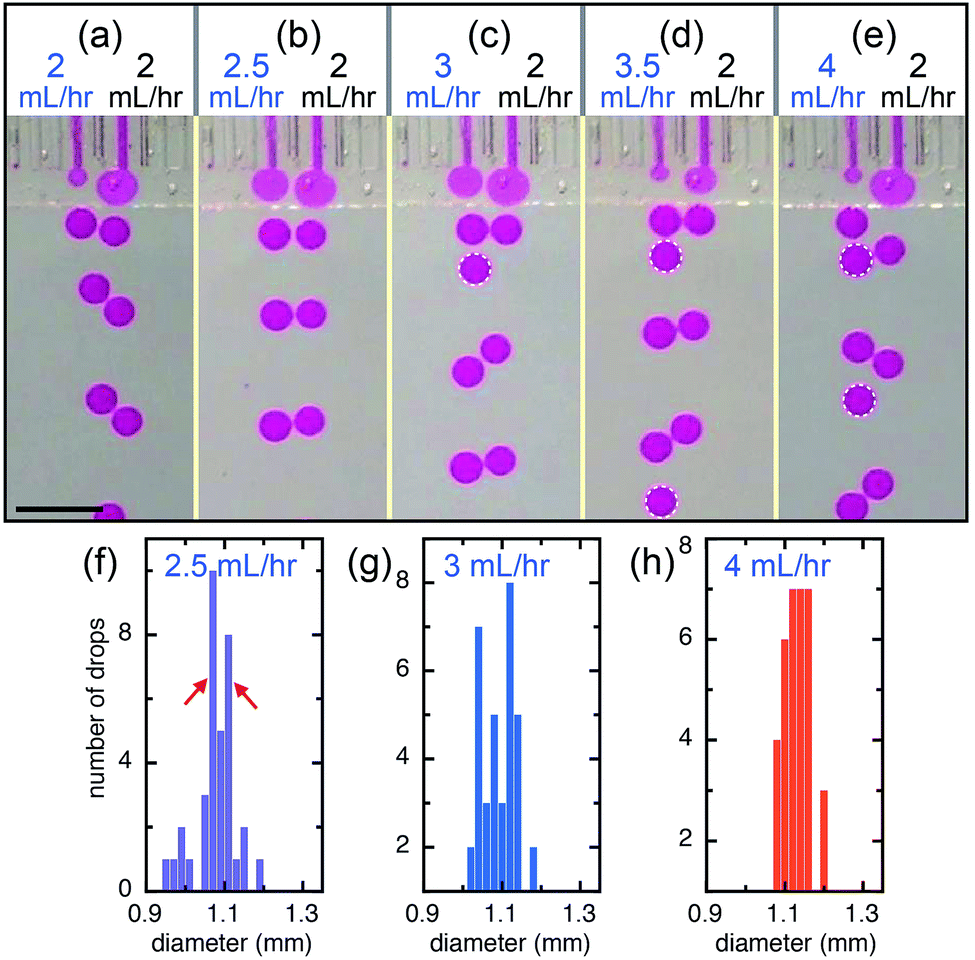 | ||
| Fig. 3 Interaction between two neighboring channels. (a) Synchronized generation of monodisperse droplets between two neighboring channels infused with flows of same rate, QL = QR = 2 mL h−1. (b) When the flow rate of the left channel increases to QL = 2.5 mL h−1, interaction between neighboring channels keep droplets generated at the same rate from the two channels. When the flow rate increases to (c) QL = 3 mL h−1, (d) QL = 3.5 mL h−1 and (e) QL = 4 mL h−1, the left channel generates one extra drop every three drops, two drops and one drop, respectively. The extra drops are highlighted by the white dashed outlines. (f), (g) and (h) Size distribution of drops generated in (b), (c) and (e), respectively. The red arrows in (f) suggest the very small size difference due to the difference in flow rate in (b). The scale bar is 3 mm. | ||
The behavior observed in two channels can be generalized to multiple channels. In a device of three channels operating simultaneously, the left and right channels generate drops at the same time while the middle channel generates drops in the interval in between, as shown in Fig. 4a. When keeping the flow rates of the left and right channels constant at QL = QR = 2 mL h−1 and changing the flow rate of the middle channel, different ratio of the production frequencies between the channels can be achieved, e.g. fL:fM:fR = 1:1:1 for QM = 2.5 mL h−1, fL:fM:fR = 3:4:3 for QM = 3 mL h−1, fL:fM:fR = 2:3:2 for QM = 3 mL h−1 and fL:fM:fR = 1:2:1 for QM = 4 mL h−1, as shown in Fig. 4b–e.
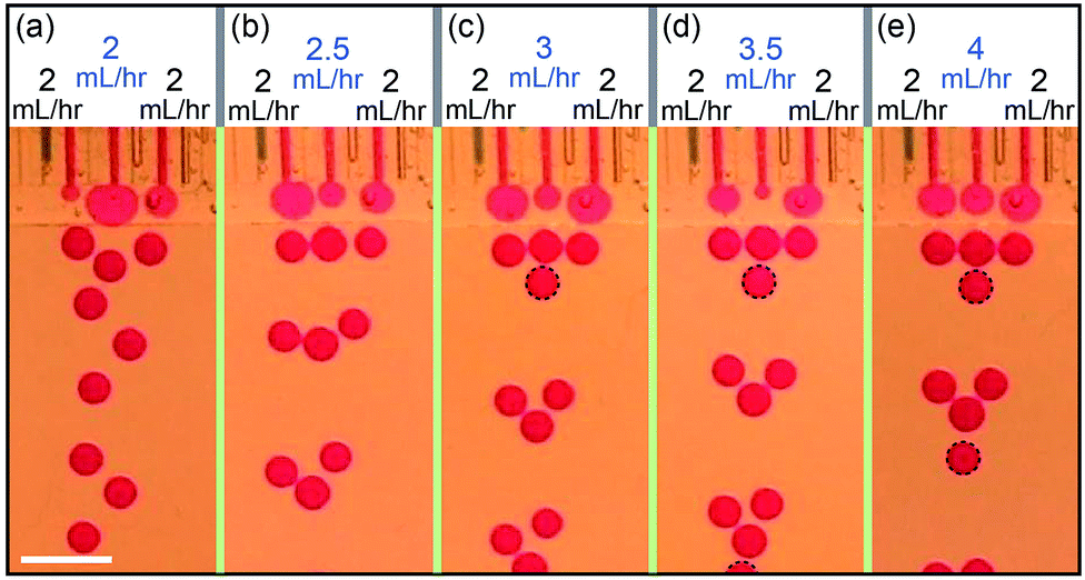 | ||
| Fig. 4 Interaction between three neighboring channels. The behavior of three channels is similar to that of two channels. When the flow rate of the middle channel (QM = 2.5 mL h−1) is slightly larger that of the left and right channels (QL = QR = 2 mL h−1), droplets are generated at same frequency. When the flow rate of the middle channel increases to QM = 3 mL h−1, QM = 3.5 mL h−1 and QM = 4 mL h−1, the middle channel generates an extra droplet every three droplets, two droplets and one droplet, respectively. The extra drops are highlighted by the black dashed outlines. The scale bar is 3 mm. | ||
The main influence of the direct contact of the flow tips of neighboring channels in the shallow plateau is physico-chemical interactions25 and strongly depends on the contact time,26 which directly impacts the features of the final emulsions. For example, at a relatively low flow rate, the flow tips of two closely spaced channels have more time in contact while expelling each other and are, therefore, more susceptible to coalescence. Eventually, the two flow tips merge together within the plateau, forming monodisperse Janus drops, as shown in Fig. 5. The drops generated by the merged flow of left and right channels (QL = QR = 1 mL h−1) are monodisperse and are slightly larger (d ∼ 1.35 mm) than that produced from a single channel (d ∼ 1.1 mm), as shown in Fig. 6a and f. By keeping the flow rate of the right channel at QR = 1 mL h−1 and increasing the flow rate of the left channel, we achieve monodisperse drops of fluids mixed at different volume ratios, e.g. VL:VR = 5:4 for QL = 1.25 mL h−1 and VL:VR = 3:2 for QL = 1.5 mL h−1, as shown in Fig. 6b, c and g. However, when the flow rate of the left channel further increases to QL = 1.75 mL h−1 and QL = 2 mL h−1, the device produces alternatively one drop from the left channel and one drop of mixed fluids from both left and right channels (Fig. 6d, e and Movie S2†); drops of mixed fluids are generally larger than that from a single channel, which shows a bimodal size distribution (Fig. 6h). In contrast to other devices containing shallow plateaus before the deep reservoir, such as the edge-based droplet generator27 and the asymmetric through-hole-array devices,28 this design allows adjustable interactions of the independently controlled different dispersed phases. Therefore, multi-component droplets can be produced by step emulsification and the composition can be tailored by virtue of the interaction occurred in the shallow plateau.
 | ||
| Fig. 5 Time sequences showing the flows of two closely spaced neighboring channels merging at the plateau and forming monodisperse Janus drops. At low flow rate, the tips of neighboring flows have more time touching each other and are more susceptible to dewetting. The fluids from the left and right channels are colored with different dyes to render them visible. The scale bar is 3 mm. | ||
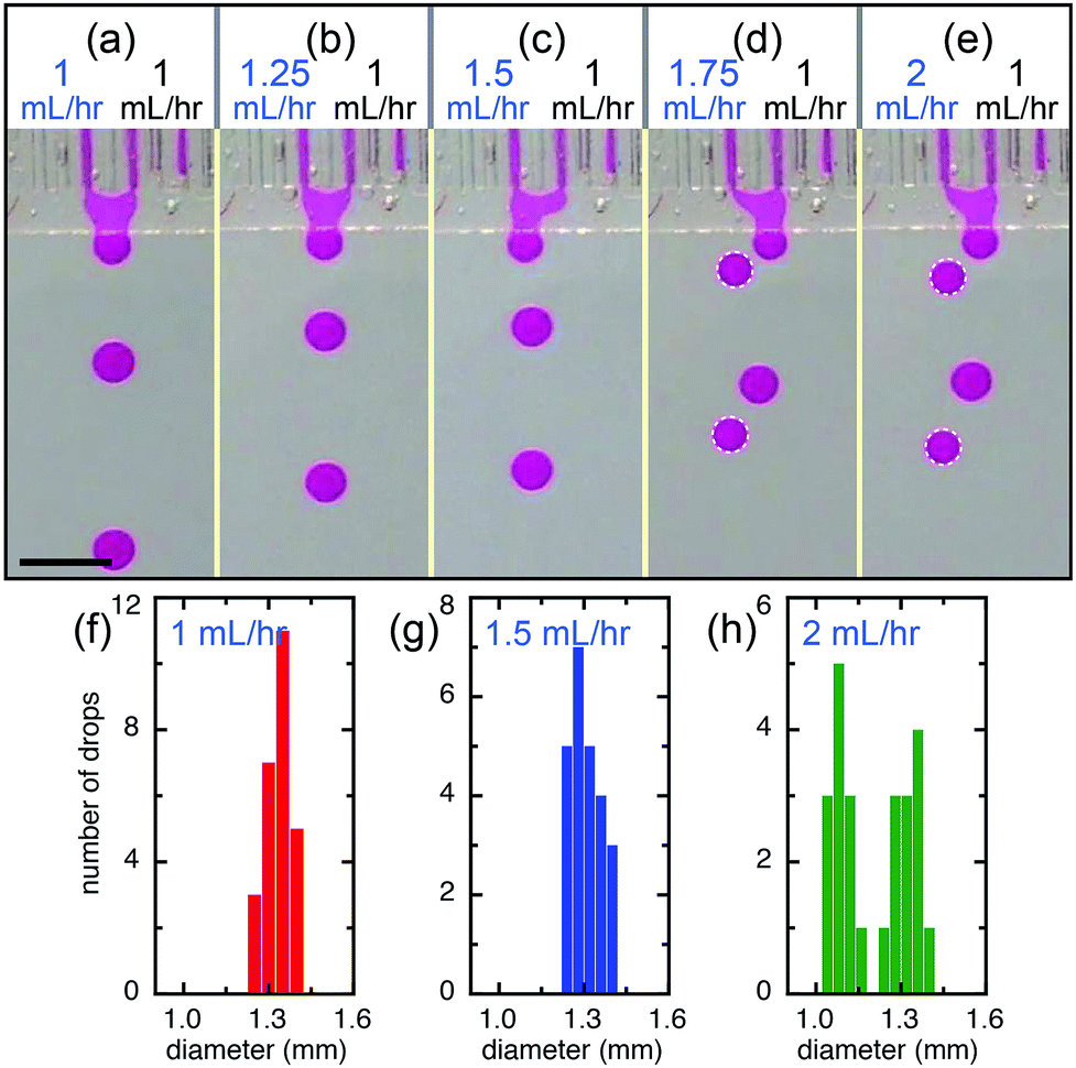 | ||
| Fig. 6 Flow dependence. The flows from neighboring channels tend to merge together before they break up. (a) The drop size of mixed fluid (flow rate QL = QR = 1 mL h−1 and volume ratio VL:VR = 1:1) is monodisperse. By increasing the flow rate of the left channel to (b) QL = 1.25 mL h−1 and (c) QL = 1.5 mL h−1, monodisperse drops of fluid mixed at different volume ratio, VL:VR = 5:4 and VL:VR = 3:2, are achieved, respectively. When the flow rate increases to (d) QL = 1.75 mL h−1 and (e) QL = 2 mL h−1, drops of fluid from left channel only and drops of mixed fluid are generated alternatively, showing bimodal distributions of drop size. The edges of drops from the left channel only are highlighted by white dashed circles. (f), (g) and (h) Size distribution of drops generated in (a), (c) and (e), respectively. The scale bar is 3 mm. | ||
The coalescence of the flow tips of neighboring channels in the shallow plateau strongly depends on the device parameters, mainly the width of the plateau, L, and the spacing of the two channels, S. In experiments, the widths of plateau are varied from 1 to 2 mm, while the spacing of the two channels is adjusted from to 1.2 to 2.8 mm. The height of the plateau is kept ∼200 μm. When S > L, it is generally considered that neighboring flow tips are not able to coalesce, since the distance between them is larger than their diameters. However, the experiments show that neighboring flow tips are pushed towards each other spontaneously and coalesce even when S > L. The phenomenon can be attributed to the fact that the continuous fluid between the neighboring tips is dragged by the two flow tips and has a higher velocity, leading to a lower pressure in the middle region. Therefore, neighboring flow tips are pushed towards each other, as shown in Fig. 7a, and the flow tips of same flow rate can always coalesce when S/L is less than 1.2, as shown in Fig. 7b. When S/L is between 1.2 and 1.7, the behavior of neighboring flow tips strongly depends on their flow rates. When the flow rates are low, the “push” effect is weak and neighboring flow tips break up into droplets alternatively. When the flow rates increase, the “push” effect becomes stronger and neighboring flow tips are able to coalesce again, as shown in Fig. 7b. The coalescence disappears, when the flow rates are too high that the flow tips do not have enough contact time. When S/L is larger than 1.7, it is too far for neighboring flow tips to coalesce. The flow behaviors eventually transition from the coalescence and alternative dripping regimes to the continuous outflow regime as the capillary number increases, as shown in Fig. 7b.
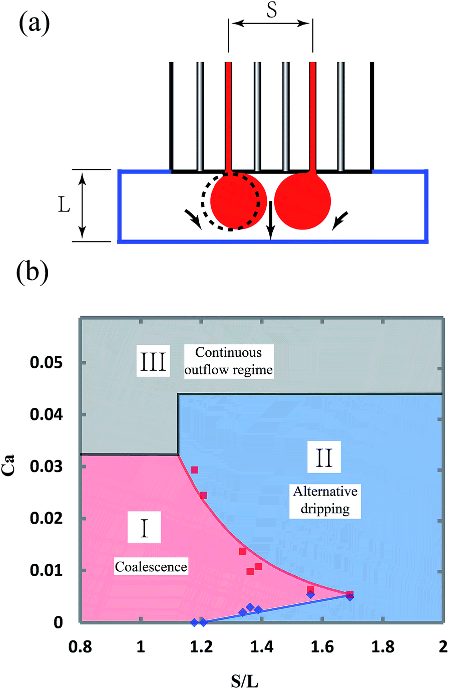 | ||
| Fig. 7 Dependence of droplet coalescence on flow rate and device geometry. (a) The flow tips from neighboring channels are pushed towards each other in the plateau, which is caused by the fact that the fluid between the flow tips has a higher velocity and thus a lower pressure than the fluid on the two sides. The black dashed line depicts the left flow tip when generated in a single channel emulsifier. (b) Three regions of flow behaviors that depend on the capillary number, Ca, and the device geometry, S/L: (I) the flow tips coalesce and break up in the dripping regime; (II) the flow tips do not coalesce and break up into droplets alternatively in the dripping regime; (III) the flow rates are too high that the step emulsification transitions to the continuous outflow regime. | ||
The conditions, at which droplets from neighboring channels coalesce, are useful in two aspects. First, in the case of producing droplets in high throughput, it is expected to put the parallel channels as closely as possible. However, the coalescence conditions indicate that the spacing of the channels must be larger than 1.2L to prevent unexpected coalescence which may lead to a high polydispersity. Second, when Janus droplets are to be produced, these coalescence conditions also show that the device parameters and the flow rates are strictly limited.
The facile device designed in this paper is robust for collective generation of milliemulsions. Fluids with different properties and compositions can be dispersed in the same device. For example, air bubbles and water droplets can also be synchronized, as shown in Fig. S4.† Because of the simple design of each production unit, mass production of monodisperse droplets that meets the industrial requirement can be achieved by parallelizing droplet generation that incorporates a large number of droplet generation units.29 Meanwhile, microcapillary films are much cheaper than the widely used single crystal silicone or PDMS chips, which is meaningful in parallelization of such milliemulsion generator. The monodisperse droplets produced by the device are useful templates for producing uniform microcapsules30 and microparticles for various applications.31–34
Conclusions
We describe a microfluidic device using a microcapillary film that offers an adjustable control of droplet production. We use a shallow plateau to join all microcapillary channels together and introduce droplet interactions including contact, bouncing and coalescence during the step-emulsification process; this cannot be achieved in isolated channels. In the shallow plateau, flow tips of neighboring channels can directly contact each other; this interaction results in self-synchronized generation of droplets in an alternating way between neighboring channels. Depending on the contact time, it is possible to manipulate the droplets' composition by coalescence to facilitate complex chemical or biological processing. In addition, because fluids are mixed at the exit, blockages due to the formation of precipitates are avoided. We anticipate that the device which produces droplets of millimeter size that are visible by naked eyes will significantly broaden the scope of applications.Acknowledgements
This work is supported by the National Natural Science Foundation of China (No. 51373153 and No. 21676244), National Basic Research Program of China (Grant No. 2015CB057301), the National Science Foundation (DMR-1310266), the Harvard Materials Research Science and Engineering Center (DMR-1420570) and the National Institutes of Health (R01EB014703). D. C. acknowledges the Youth Funds of the State Key Laboratory of Fluid Power and Mechatronic Systems (Zhejiang University) and “Thousand Talents Program” for Distinguished Young Scholars. C. X. Z. acknowledges financial support from Australian Research Council through the award of an 2014 ARC Future Fellowship (FT140100726).References
- L. L. Schramm, Emulsions, foams, and suspensions: fundamentals and applications, John Wiley & Sons, Weinheim, 2006 Search PubMed.
- A. B. Theberge, F. Courtois, Y. Schaerli, M. Fischlechner, C. Abell, F. Hollfelder and W. T. Huck, Angew. Chem., Int. Ed., 2010, 49, 5846–5868 CrossRef CAS PubMed.
- W. J. Duncanson, T. Lin, A. R. Abate, S. Seiffert, R. K. Shah and D. A. Weitz, Lab Chip, 2012, 12, 2135–2145 RSC.
- T. Thorsen, R. W. Roberts, F. H. Arnold and S. R. Quake, Phys. Rev. Lett., 2001, 86, 4163 CrossRef CAS PubMed.
- S. L. Anna, N. Bontoux and H. A. Stone, Appl. Phys. Lett., 2003, 82, 364–366 CrossRef CAS.
- Z. Li, A. Leshansky, L. Pismen and P. Tabeling, Lab Chip, 2015, 15, 1023–1031 RSC.
- T. Kawakatsu, Y. Kikuchi and M. Nakajima, J. Am. Oil Chem. Soc., 1997, 74, 317–321 CrossRef CAS.
- S. Sugiura, M. Nakajima, S. Iwamoto and M. Seki, Langmuir, 2001, 17, 5562–5566 CrossRef CAS.
- R. Dangla, E. Fradet, Y. Lopez and C. N. Baroud, J. Phys. D: Appl. Phys., 2013, 46, 114003 CrossRef.
- E. van der Zwan, K. Schroën and R. Boom, Langmuir, 2009, 25, 7320–7327 CrossRef CAS PubMed.
- S. Sugiura, M. Nakajima and M. Seki, Langmuir, 2002, 18, 3854–3859 CrossRef CAS.
- C. Priest, S. Herminghaus and R. Seemann, Appl. Phys. Lett., 2006, 88, 024106 CrossRef.
- R. Dangla, S. C. Kayi and C. N. Baroud, Proc. Natl. Acad. Sci. U. S. A., 2013, 110, 853–858 CrossRef CAS PubMed.
- N. Mittal, C. Cohen, J. Bibette and N. Bremond, Phys. Fluids, 2014, 26, 082109 CrossRef.
- F. Malloggi, N. Pannacci, R. Attia, F. Monti, P. Mary, H. Willaime, P. Tabeling, B. Cabane and P. Poncet, Langmuir, 2009, 26, 2369–2373 CrossRef PubMed.
- L. Arriaga, E. Amstad and D. Weitz, Lab Chip, 2015, 15, 3335–3340 RSC.
- V. Chokkalingam, S. Herminghaus and R. Seemann, Appl. Phys. Lett., 2008, 93, 254101 CrossRef.
- I. Kobayashi, S. Mukataka and M. Nakajima, Langmuir, 2005, 21, 7629–7632 CrossRef CAS PubMed.
- I. Kobayashi, M. Nakajima, K. Chun, Y. Kikuchi and H. Fujita, AIChE J., 2002, 48, 1639 CrossRef CAS.
- B. Hallmark, F. Gadala-Maria and M. R. Mackley, J. Non-Newtonian Fluid Mech., 2005, 128, 83–98 CrossRef CAS.
- B. Hallmark, M. R. Mackley and F. Gadala-Maria, Adv. Eng. Mater., 2005, 7, 545–547 CrossRef CAS.
- J. Cao, Z. Xu, B. Wang and R. Chen, J. Mater. Sci., 2012, 47, 8188–8196 CrossRef CAS.
- G. T. Vladisavljevic, I. Kobayashi and M. Nakajima, Microfluid. Nanofluid., 2011, 10, 1199–1209 CrossRef CAS.
- S. Sugiura, M. Nakajima, N. Kumazawa, S. Iwamoto and M. Seki, J. Phys. Chem. B, 2002, 106, 9405–9409 CrossRef CAS.
- I. Akartuna, D. M. Aubrecht, T. E. Kodger and D. A. Weitz, Lab Chip, 2015, 15, 1140–1144 RSC.
- F. Krause, X. Li and U. Fritsching, Engineering Applications of Computational Fluid Mechanics, 2014, 5, 406–415 CrossRef.
- K. van Dijke, G. Veldhuis, K. Schroen and R. Boom, Lab Chip, 2009, 9, 2824–2830 RSC.
- I. Kobayashi, Y. Wada, K. Uemura and M. Nakajima, Microfluid. Nanofluid., 2008, 5, 677–687 CrossRef CAS.
- H. H. Jeong, D. Issadore and D. Lee, Korean J. Chem. Eng., 2016, 33, 1757–1766 CrossRef CAS.
- C. G. Yang, R. Y. Pan and Z. R. Xu, Chin. Chem. Lett., 2015, 26, 1450–1454 CrossRef CAS.
- Y. K. Chan, D. Wong, H. K. Yeung, P. K. Man and H. C. Shum, Invest Ophth Vis Sci, 2015, 56, 1014–1022 CrossRef PubMed.
- W. F. Lai and H. C. Shum, Nanoscale, 2016, 8, 517–528 RSC.
- Q. M. Ma, Y. Song, G. Baier, C. Holtze and H. C. Shum, J. Mater. Chem. B, 2016, 4, 1213–1218 RSC.
- W. Wang, M. J. Zhang and L. Y. Chu, Acc. Chem. Res., 2014, 47, 373–384 CrossRef CAS PubMed.
Footnote |
| † Electronic supplementary information (ESI) available: Sizes of droplets produced in different flow rates, process of step-emulsification by a single channel and four channels, time sequences showing three synchronized channel while the left channel is air bubble, and videos showing generation of droplets by three channels and alternatively production of mixed and unmixed droplets. See DOI: 10.1039/c7ra00935f |
| This journal is © The Royal Society of Chemistry 2017 |