
 Open Access Article
 This Open Access Article is licensed under a
 Creative Commons Attribution 3.0 Unported Licence
Real 3D microsphere lasers by femtosecond laser processing
Zhi-Shan Hou,
Qiu-Lan Huang,
Xue-Peng Zhan,
Ai-Wu Li * and
Huai-Liang Xu*
* and
Huai-Liang Xu*
State Key Laboratory on Integrated Optoelectronics, College of Electronic Science and Engineering, Jilin University, 2699 Qianjin Street, Changchun 130012, China. E-mail: liaw@jlu.edu.cn; huailiang.xu@gmail.com
First published on 15th March 2017
Abstract
In this article, we have mainly demonstrated the fabrication of a dye-doped polymer whispering gallery mode (WGM) microsphere by femtosecond laser two-photon polymerization, which shows good surface smoothness with a fabrication spatial resolution beyond the diffraction limit. The microcavity shows excellent lasing performance with a quality factor of ∼3000. We have found that the lasing behavior of the 3D microlaser depends strongly on the diameter of the microsphere, that is, the lasing output changes from multimode to single mode gradually with the shift of laser wavelength when the diameter of the fabricated microsphere decreases. Our results can provide an easier solution for fabricating 3D single-mode microlasers with controlled resonance wavelength.
Femtosecond laser processing is a complicated technology which involves an ultrafast laser,1 microscopy, high-precision positioning, three-dimensional graphics modeling and a photochemical reaction.2,3 Nevertheless, femtosecond laser processing, as a modern manufacturing technology, has superior advantages in many aspects, such as high resolution (due to the nonlinear interaction of the femtosecond laser and transparent materials, the prepared structures have resolution far beyond the optical diffraction limit4–8), low thermal damage (the pulse duration is short enough to minimize heat generation and accumulation), real 3D (any 3D structure can be easily fabricated by scanning point-by-point) and a low request for the working environment (the process can be achieved under mild conditions). Therefore, it has received considerable attention and has been widely used in many domains, such as optical storage9,10 and microfluidics.11–13 Until now, various two-dimensional and three-dimensional micro-nano photonic devices with high quality have been successfully demonstrated by femtosecond laser processing.14–17
Whispering gallery mode (WGM) microcavities which possess high quality factor (Q) and small volume have shown promising applications in many areas such as sensing,18 lasing5,6 and optical information processing.19 In addition, they have been widely used in fundamental researches, such as cavity quantum electrodynamics.20 High-Q WGM microcavities have been well-prepared in various materials by different technologies, such as fused taper technique and wet etching technology. With the development of laser technique, femtosecond two-photon micro-processing technology has also been reported on the fabrication of WGM microcavities in early 2010.21 However, those microcavities fabricated by femtosecond laser were mainly about two-dimensional or false three-dimensional (low space complexity).22
The microspheres (real 3D) have demonstrated higher Q-factor than the micro-rings or micro-disks, and wherever the pump light incident is on the microsphere, a suitable incidence angle will always achieve total reflection along the sphere boundary, herein, the femtosecond laser processing is adopted to fabricate dye-doped polymer microspheres. Different diameters (5–25 μm) of microspheres with high surface smoothness are easily achieved by taking advantage of the two-photon polymerization. Lasing behaviors of these microspheres are collected and investigated by spectrometer under picosecond laser pumping. In this way, the lasing behavior of the 3D microlaser depends strongly on the diameter of the microsphere are verified.
In the experimental process, SU-8 negative photoresist was used as the main material, with clean glass used as the substrate. Firstly, monomers was dissolved in cyclopentanone with a weight concentration ratio of 1![[thin space (1/6-em)]](https://www.rsc.org/images/entities/char_2009.gif) :2 to reduce the viscosity of photoresist and make the photoresist convenient for spin-coating. Secondly, rhodamine 6G (R6G, as gain medium in the microsphere laser in this work) were dissolved in ethanol solution at a concentration of 10 wt%. Thirdly, the two mentioned above were mixed to realize R6G doped SU-8 solution at a concentration of 1.5 wt%, the chosen concentration of 1.5 wt% is a trade-off between lasing action and fabrication process. In fact, concentrations between 1 wt% and 2 wt% are satisfying. The solution was spin-coated on a cover glass rinsed with acetone, ethanol, and deionized water. At last, the glass with photoresist was prebaked on a heating stage at 95 °C for 2 h to make the organic solvent volatilize to increase the surface adhesion.6 The laser pulses (central wavelength: 800 nm; pulse width: 120 fs; repetition rate: 80 MHz) were tightly focused on the sample by an oil objective, as shown in Fig. 1. The light spot scanned in three-dimensional (3D) were achieved in strict accordance with the blueprint by the mirrors and the piezoelectric platform. Two-photon absorption occurred on the focus spot region and photoinitiator would produce an acid, which induces intermolecular cross-linked of SU-8 during the post bake process (95 °C for 15 min).
:2 to reduce the viscosity of photoresist and make the photoresist convenient for spin-coating. Secondly, rhodamine 6G (R6G, as gain medium in the microsphere laser in this work) were dissolved in ethanol solution at a concentration of 10 wt%. Thirdly, the two mentioned above were mixed to realize R6G doped SU-8 solution at a concentration of 1.5 wt%, the chosen concentration of 1.5 wt% is a trade-off between lasing action and fabrication process. In fact, concentrations between 1 wt% and 2 wt% are satisfying. The solution was spin-coated on a cover glass rinsed with acetone, ethanol, and deionized water. At last, the glass with photoresist was prebaked on a heating stage at 95 °C for 2 h to make the organic solvent volatilize to increase the surface adhesion.6 The laser pulses (central wavelength: 800 nm; pulse width: 120 fs; repetition rate: 80 MHz) were tightly focused on the sample by an oil objective, as shown in Fig. 1. The light spot scanned in three-dimensional (3D) were achieved in strict accordance with the blueprint by the mirrors and the piezoelectric platform. Two-photon absorption occurred on the focus spot region and photoinitiator would produce an acid, which induces intermolecular cross-linked of SU-8 during the post bake process (95 °C for 15 min).
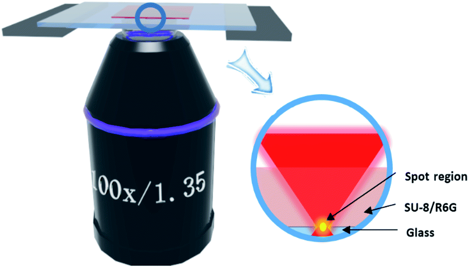 | ||
| Fig. 1 Schematic diagram of femtosecond laser processing system for preparing dye-doped polymer microsphere (insert: amplification of focus spot region). | ||
The designed microsphere lasers with different cavity diameters were “directly written” through the fabrication and post-bake treatment. As an example, the optical microscope and scanning electron microscope images of a fabricated microcavity (DIA 10 μm) are shown in Fig. 2(a) and (b), which exhibit the expected ultra-smooth surface and sphere structure (seen from (c), the surface roughness of the sphere was less than 80 nm) that are highly essential to reduce light scattering in the microcavity and thus remain a high Q-factor.23 As shown in the sketch (inserted in Fig. 2(d)), a pedestal was designed for the microsphere in order to reduce scattering loss from the glass substrate, which manifests relatively deeper red color in the central portion of the optical microscope image in Fig. 2(a). A 532 nm picosecond laser was focused on the microcavity and the lasing signal was collected by a lens and then sent to a spectrometer. The focal spot size was about 50 μm as shown by the green spot in Fig. 2(d), which is much larger than that of the microcavity and thus the intensity of pump laser around the device is distributed uniformly.
 | ||
| Fig. 2 (a) Top-view optical microscopic images of 10 μm microsphere laser, scale bar: 10 μm. (b, c) SEM image of 10 μm microsphere laser, scale bar: (b) 1 μm; (c) 100 nm. (d) Microspheres measured from CCD, green light: 532 nm pump, (insert: microsphere designed). | ||
With the 532 nm pump, the R6G-doped SU-8 can emit fluorescence in the spectral range of 580–680 nm, and thus resonant whispering gallery laser modes in this spectral region can be eventually formed in the microsphere cavities. Fig. 3(a) and (f) show the spectra of a microsphere (DIA 10 μm) pumped with different pump energy densities. It can be clearly seen that as the energy density is low (∼240 μJ cm−2), the microsphere results in weak fluorescence without lasing behavior, while as the pumping power is gradually increased, lasing occurs with some laser peaks appeared, which increase rapidly with the increase of the pump laser power. It is well known that free spectral range of WGM satisfies the formula: FSR ≈ λ2/2πnr,24 and thus for the prepared microsphere with n (refractive index) being 1.57 and λ (the lasing peak) being 601.64 nm, the FSR is calculated to be ∼7.34 nm, which is in a good agreement with the experimental result (∼7.46 nm) obtained from the insert in Fig. 3(a), which verifies the resonant WGM in the prepared microsphere. Similarly, lasing actions from different sizes of fabricated microspheres can also be observed, as shown in Fig. 3(b)–(e). The diameters of these microspheres are (b) 5 μm, (c) 15 μm, (d) 20 μm and (e) 25 μm, respectively. It can be seen from Fig. 3(b)–(e) that when the microcavity diameter is 5 μm, there is only one lasing peak appearing on the laser spectrum, while as the diameter increase to 15 μm, the number of lasing modes increase to 3, the number of lasing modes increases and the interval between the lasing peaks (FSR) becomes smaller. This can be understood from the relation of FSR ≈ λ2/2πnr, in which the FSR increases as the cavity length decreases. It can be seen from Fig. 3(a), when energy density is low (295–325 μJ cm−2), there is only one peak at ∼601.74 nm, when density higher (390–680 μJ cm−2), the mode at 590.5 nm, 596.1 nm, 609.1 nm, 611.3 nm appear. So the microsphere with diameter of 5 microns show only one lasing peak in this experiment, and we believe another modes would appear too if we continue to increase power density, however, such high power would bleach the dye and burnt the device. It can be seen from Fig. 4 that the main resonant wavelength is ∼598 nm for the microsphere with the diameter of 5 μm, which gradually increases as the microsphere diameter increases. The observed red shift of the main resonant peak as a function of the microsphere diameter is consistent with previous observations.10,25 In a WGM mode microcavity, the resonant wavelength (λ) and the radius of the resonant cavity (r) satisfy the relation: 2πnr = mλm, thus when the radius increases, the resonant wavelength would also increase to satisfy the above relation.
 | ||
| Fig. 3 (a) Lasing spectra of the microsphere with a diameter of 10 μm under different pumping energies (waterfall) (insets: detailed information for the spectrum under the pump of 545 μJ cm−2 energy density). (b–e) Lasing spectra from microspheres with diameters of 5 μm, 15 μm, 20 μm, 25 μm under the appropriate energy density respectively. (f) The lasing threshold characteristic in (a). | ||
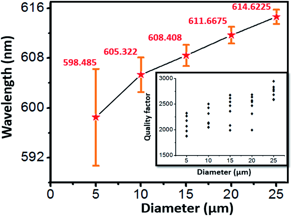 | ||
| Fig. 4 Main resonant laser wavelength vs. diameter of the microsphere (insert: Q-factors measured for the microspheres with different diameters). | ||
In addition, it can be noted from Fig. 4 that the main lasing spectrum peaks of the microspheres with the diameters of 10 μm, 15 μm, 20 μm and 25 μm approximately follow a linear relationship. The large uncertainties with the smaller microsphere diameter may caused by the micromachining resolution. Suppose that all the parameters remain constant in FsLDW and the accidental errors is about 0.5 μm, and thus the errors account for 10% for the 5 μm microsphere, which would become 5% for the 10 μm one. Fortunately, there is no doubt that the errors could be further decreased efficiently by optimizing the optical path and machining parameters.
The full width at half maximum (FWHM) of the lasing spectral line was measured to be ∼0.25 nm determined by a He–Ne laser and a spectrometer.6 Since the resolution of the spectrometer is ∼0.2 nm, which is comparable to the measured lasing line of the microsphere, the determined Q-factor has a large uncertainty. Even so, it is found that the microsphere with larger diameter is more likely to have a higher Q-factor, e.g. ∼2800 and ∼2100 for the 25 μm and 5 μm microscopheres, respectively, as shown by the inset in Fig. 4, in which the errors in microspheres are plotted.
Summary
In summary, we have fabricated dye-doped polymer 3D microspheres with smooth surface by femtosecond laser two-photon polymerization, and showed the whispering gallery mode lasing performance of these microstructures. The lasing behaviors of the 3D microlasers depend strongly on the diameter of the microsphere, that is, the lasing output changes from multimode to single mode with the blue shift of laser wavelength when the diameter of the fabricated microsphere decreases. Our results provide an easy solution for fabricating 3D single-mode microlaser with controlled resonance wavelength.Acknowledgements
This research was supported by the National Basic Research Program of China under grants no. 2014CB921302 and State Key Laboratory of Luminescence and Applications.Notes and references
- R. B. Gao, H. Y. Wang, Y. W. Hao, L. M. Fu, H. H. Fang, Y. Jiang, L. Wang, Q. D. Chen, H. Xia, L. Y. Pan, Y. G. Ma and H. B. Sun, J. Phys. Chem. B, 2010, 114, 128–134 CrossRef PubMed.
- Y. L. Zhang, L. Guo, S. Wei, Y. Y. He, H. Xia, Q. D. Chen, H. B. Sun and F. S. Xiao, Nano Today, 2010, 5, 15–20 CrossRef CAS.
- L. Guo, Y. L. Zhang, R. Q. Shao, S. Y. Xie, J. N. Wang, X. B. Li, F. Jiang, H. B. Jiang, Q. D. Chen, T. Zhang and H. B. Sun, Carbon, 2012, 50, 1667–1673 CrossRef CAS.
- S. Kawata, H. B. Sun, T. Tanaka and K. Takada, Nature, 2001, 412, 697–698 CrossRef CAS PubMed.
- X. P. Zhan, X. L. Zhang, H. H. Fang, Q. D. Chen, H. L. Xu and H. B. Sun, IEEE Photonics Technol. Lett., 2016, 28, 351–354 CrossRef.
- Q. L. Huang, X. P. Zhang, Z. S. Hou, Q. D. Chen and H. L. Xu, Opt. Commun., 2015, 362, 73–76 CrossRef.
- M. Schumann, T. Buckmann, N. Gruhler, M. Wegener and W. Pernice, Light: Sci. Appl., 2014, 3, e175, DOI:10.1038/lsa.2014.56.
- J. F. Ku, Q. D. Chen, X. W. Ma, Y. D. Yang, Y. Z. Huang, H. L. Xu and H. B. Sun, IEEE Photonics Technol. Lett., 2015, 27, 1157–1160 CrossRef.
- Z. Peter, W. M. C. James and G. Min, Nature, 2009, 459, 410–413 CrossRef PubMed.
- J. R. Qiu, K. Miura, H. Inouye, J. Nishii and K. Hirao, Nucl. Instrum. Methods Phys. Res., Sect. B, 1998, 141, 699–703 CrossRef CAS.
- D. Wu, Q. D. Chen, L. G. Niu, J. N. Wang, J. Wang, R. Wang, H. Xia and H. B. Sun, Lab Chip, 2009, 9, 2391–2394 RSC.
- Y. V. White, M. Parrish, X. X. Li, L. M. Davis and W. Hofmeister, Proc. SPIE, 2008, 7039 DOI:10.1117/12.799855.
- C. Hnatovsky, R. S. Taylor, E. Simova, V. R. Bhardwaj, D. M. Rayner and P. B. Corkum, Opt. Lett., 2005, 30, 1867–1869 CrossRef CAS PubMed.
- Y. L. Sun, W. F. Dong, L. G. Niu, T. Jiang, D. X. Liu, L. Zhang, Y. S. Wang, D. P. Kim, Q. D. Chen and H. B. Sun, Light: Sci. Appl., 2014, 3, e129, DOI:10.1038/lsa.2014.10.
- Y. L. Zhang, Q. D. Chen, H. Xia and H. B Sun, Nano Today, 2010, 5, 435–448 CrossRef CAS.
- H. Xia, J. Wang, Y. Tian, Q. D. Chen, X. B. Du, Y. L. Zhang, Y. He and H. B. Sun, Adv. Mater., 2010, 22, 3204–3207 CrossRef CAS PubMed.
- Z. S. Hou, S. M. Sun, B. Y. Zheng, R. Z. Yang and A. W. Li, RSC Adv., 2015, 5, 77847–77850 RSC.
- H. Li, L. Shang, X. Tu, L. Liu and L. Xu, J. Am. Chem. Soc., 2009, 131, 16612–16613 CrossRef CAS PubMed.
- M. T. Hill, H. J. S. Dorren, T. de Vries, X. J. M. Leijtens, J. H. den Besten, B. Smalbrugge, Y. S. Oei, H. Binsma, G. DjanKhoe and M. K. Smit, Nature, 2004, 432, 206–209 CrossRef CAS PubMed.
- S. M. Spillane, T. J. Kippenberg, O. J. Painter and K. J. Vahala, Phys. Rev. Lett., 2003, 91, 043902 CrossRef CAS PubMed.
- J. F. Ku, Q. D. Chen, R. Zhang and H. B. Sun, Opt. Lett., 2011, 36, 2871–2873 CrossRef CAS PubMed.
- H. L. Xu and H. B. Sun, Sci. China: Phys., Mech. Astron., 2015, 58, 114202 CrossRef.
- T. Grossmann, T. Wienhold, U. Bog, T. Beck, C. Friedmann, H. Kalt and T. Mappes, Light: Sci. Appl., 2013, 2, e82, DOI:10.1038/lsa.2013.38.
- H. H. Fang, R. Ding, S. Y. Lu, Y. D. Yang, Q. D. Chen, J. Feng, Y. Z. Huang and H. B. Sun, Laser Photonics Rev., 2013, 7, 281–288 CrossRef CAS.
- T. X. Liu and F. M. Li, Chin. J. Lasers, 1987, 14, 141–146 Search PubMed.
| This journal is © The Royal Society of Chemistry 2017 |