 Open Access Article
Creative Commons Attribution 3.0 Unported Licence
Numerical investigation on the elastic–plastic transition of a cylindrical coating/substrate composite under normal compression
Yongtao Mu ,
Ming Liu* and
Yongqiang Zhao
School of Mechatronics Engineering, Harbin Institute of Technology, Harbin 150001, People’s Republic of China. E-mail: liuming@hit.edu.cn; Tel: +86 451 86403799
First published on 9th March 2017
Abstract
In order to study the yielding resistance of a coated component in line contact, a cylindrical coating/substrate system contacting a rigid plane was simulated via a plane-strain model. For super-thick coatings, the critical load, contact width and interference were derived for the onset of plastic yielding on the axis of symmetry by a function approximation method. The results indicated the geometrical and mechanical properties of the loaded coating displayed an important influence on these threshold values. For thinner coatings, the Von Mises stress distribution along the axis of symmetry was investigated using a finite element method, of which a pronounced discontinuity at the interface was found by increasing the elasticity modulus of the coating relative to the substrate. Furthermore, an additional stress was induced by the binding constraints imposed at the coating/substrate interface, thus resulting in a weakened resistance to the plastic initiation in relatively thin coatings. In light of finite element results, the initial yield position may be located either within the coating, in the substrate or at the interface between them with the ratio t/R of coating thickness over the substrate radius changing. Besides, when t/R was very small, the total interference of the coated cylinder was mainly attributed to the substrate deformation. With t/R ratio becoming larger, the coating compression became comparable to the substrate value. When t/R had large values, the coating contraction served as a dominant contributor to the composite interference.
1. Introduction
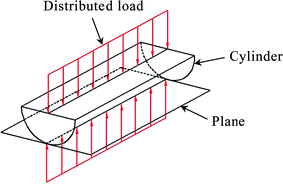
Thin film coatings are widely used in many engineering applications to enhance the tribological performance of metal parts in contact and in relative sliding.1–8 The elastic–plastic deformation of a coating/substrate system is a major factor that affects the tribology properties of a contact surface. The elastic–plastic transition may occur either within the coating, in the substrate or at their interface, accordingly it can lead to the fracture of the coating, or deformation of the substrate, or even coating delamination from the substrate. In many cases, the mechanical components interact with counterparts that are in line contact during a working process, such as cylindrical gears,9 bearings10 and clutches,11 etc., which have a complex stress and strain mechanism under normal loading. Therefore, it is imperative to study the plasticity inception of coating/substrate composites that are in line contact for the failure analysis of loaded elements.For line contact problems, a cylinder pressing a plane is commonly adopted as the basic model for researching the deformation mechanism of longitudinal objects, as shown in Fig. 1. Many mechanical investigations have been accomplished with regard to the line contact of uniform materials through the general model stated above. Liu et al. studied the adhesive contact mechanics of a long rigid cylinder on an infinite half space comprising incompressible elastic material based on small strain theory.12 Saito et al. investigated the critical conditions of rolling resistance in respect to an elastic micro-cylinder in adhesional contact with a rigid surface using a combined theoretical/computational approach.13 Jin et al. analytically studied the adhesive contact of a rigid cylinder on an elastic power-law graded half-space with the theory of a weakly singular integral equation and an orthogonal polynomial method.14 Zhupanska et al. presented an exact solution to the problem of indentation with friction of a rigid cylinder with an elastic half-space.15 Qiu et al. investigated the skew sliding of an elastic cylinder along an elastically similar half-plane and found the effect of surface strain on the local slip angle.16 Li et al. built a finite element model for the spatial contact behavior of a plate and a cylinder on account of gear transmission, which illustrated the influence of element size on contact force in different curvatures.17 Pereira et al. proposed an analytical model describing the cylindrical contact force as an explicit function of the penetration.18 Chiu et al. presented a solution for the three-dimensional cylindrical contact by a numerical iterative technique, which determined the contact pressure, as well as an elastic approach in considering the cylinder effect.19 Hunter studied the rolling contact of a rigid cylinder with a half space, considering the asymmetry through introducing viscoelastic effects.20 Doca et al. studied the frictional contact problems between a mild steel cylinder and an aluminium alloy block undergoing finite elastoplastic strains,21 and compared the predictions with experimental observations.22 Chen et al. found a possible rolling of an elastic cylinder adhering on an elastic substrate subject to a strain gradient and established a criterion for the initiation of rolling.23
With regards to the involved materials having a non-homogeneous characteristic, Meijers presented an asymptotic solution for the contact problem between a rigid cylinder and an elastic layer fastened to a rigid base, by assuming no friction and a long enough dimension to ensure a plane strain.24 Stupkiewicz et al. employed a plane-strain element to simulate the contact problem of a rigid cylinder sliding against a coated layer, where the elastohydrodynamic lubrication effect was taken into account.25 Proudhon et al. simulated the wear of a coated plate in contact with an elastic cylinder by a plain strain finite element method using an updated Lagrangian formulation.26 Saka et al. studied the contact behavior of a rigid cylinder indenting an elastoplastic two-layer half-space by a finite element method.27,28 Gupta et al. calculated the numerical solutions of the contact pressure and contact area by using an integral transform technique for the problem of a coated flat pressed by an elastic cylinder.29 Alinia et al. investigated the subsurface stress field in a functionally graded coating–substrate system induced by a rolling rigid cylinder with a Fourier transform technique, where the effects of the stiffness ratio and the interface shear modulus ratio of the coating and substrate on the stress distributions were analyzed throughout the system.30 Guler et al. investigated the frictional contact problem of a graded coating/substrate system under the action of a sliding cylinder,31 furthermore, the rolling contact problems were considered for all possible stick/slip regimes by comprehensive parametric analysis.32,33 Cole et al. studied the contact pressure distribution between a smooth cylinder and a coated flat, and they also found a numerical solution to the elastic stress field in a multi-layer system.34 Komvopoulos carried out an elastic–plastic finite element analysis on a TiN/Ti system indented by a rigid cylinder, finding that the coating thickness had a significant effect on the initiation and development of the plastic zone.35 Yang et al. performed a dynamic finite element analysis on an elastic–plastic multi-layered system indented by a rigid cylinder via a plane-strain model.36 Gong et al. researched the surface cracking in a multi-layered medium due to the sliding of a cylindrical rigid asperity using linear elastic fracture mechanics and a finite element method.37 Njiwa et al. modeled a coated flat under cylindrical indentation using a boundary element approach, demonstrating the sub-surface stress field and its discontinuity at the coating–substrate interface depended crucially on the relative Young’s moduli, film thickness and Poisson ratio of the coating and substrate.38 Djabella et al. performed a finite element analysis for the elastic contact between a coating/substrate flat and a rigid cylindrical indenter based on plane strain model, where the frictional sliding at the coated surface was considered under a combined normal and tangential load.39,40 Jahedi et al. carried out an elastic finite element investigation for a graded coated substrate in frictional contact with rigid cylindrical roller.41 Moreover, mechanical investigations about the line contact were studied by two coated cylinders in relative sliding or rolling.42,43
As can be seen from the aforementioned literature review, for a coating/substrate composite, most of the contact investigations in cylinder on plane model were focused on a coated flat and in the elastic range, but relatively few calculations have solved this for a coated cylinder, especially with regards to the plastic yielding. Therefore, in the current research the plasticity inception of a cylindrical coating/substrate composite in contact with a rigid flat was simulated in light of a plane strain model, as well as changing the ratio of the coating thickness over the substrate radius and the relative mechanical properties of the composite system. Some critical parameters were obtained for the large value of the coating thickness relative to substrate radius. Nevertheless, when the coating was relatively thin, the elastic–plastic transition along the axis of symmetry of the loaded cylinder was studied by a finite element method, and the additional stress and its discontinuity at the coating–substrate interface were observed under various simulation parameters. The present achievements may open the way for wider research on the contact mechanics of coated cylindrical components, thus avoiding the need of an inaccurate trial and error approach for designing the optimal coating.
2. Hertz contact model
2.1 Contact schematic
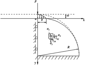
For the super coating thickness relative to the substrate radius, the substrate deformation is negligible due to its far distance from the contact zone, so the contact model of a coated cylinder and a rigid flat can consider only the coating strain on basis of Hertz theory. Fig. 2 schematically presents a plane-strain model for the cylindrical coating loaded by a rigid flat under perfect slip conditions. The coating material is assumed to be elastic and isotropic before the onset of plastic yielding, of which the Poisson’s ratio ν varies in the range of 0.2 to 0.5. Nothing but normal load is applied to the rigid flat. It is adequate to take only half of the semicircle into account due to the axisymmetric cylinder and loading. The degrees of freedom of the semicircular base are restricted in vertical and radial directions. Meanwhile, the degrees of freedom of the axis of symmetry are restricted in the radial direction. The rest of the quarter circle is free except for a normal compression exerted by the contacting rigid flat. The dashed and solid lines in the schematic denote the outlines of the bodies in contact with each other before and after loading, respectively. The contact area with a width 2b and an interference ω correspond to the normal load P. Both ω and b are supposed to be much smaller than the composite radius R. A Cartesian coordinate system is established on the quarter circle after loading, whose origin o is located at the center of the contact area and its x-axis, y-axis and z-axis are parallel to the radial, vertical and axial directions of the cylindrical plane, respectively.2.2 Stress distribution along the axis of symmetry
According to the Hertz solution,44 the contact pressure of the compressed coating has a semi-elliptical distribution in a plane-strain model, that is
 | (1) |
 | (2) |
The half width b of the contact area is written as
 | (3) |
 | (4) |
Since the axial deformation is restricted for the plane-strain model, the shear stress components τzx, τzy, τxz, τyz and the axial strain εz are equal to zero, that is
 | (5) |
So, based on Hooke’s law, the normal stress components σx, σy, σz in the plane-strain model satisfy a relation of
| σz = ν(σx + σy) | (6) |
Because the shear stress components τxy and τyx on the axis of symmetry of the coating are all equal to zero,44 combining eqn (5), the normal stress components σx, σy, σz on the axis of symmetry are the three principal stresses, and the directions of the coordinate axis are the principal directions. Then the stress field along the y-axis which is normal to the contact area at the contact center is written as ref. 44
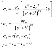 | (7) |
2.3 Yielding inception and critical parameters
The Von Mises criterion is proposed to evaluate the elastic–plastic transition of the coating materials,46 which is expressed as
 | (8) |
 | (9) |
Fig. 3 presents the function graph of the dimensionless stress σeq/pm vs. the dimensionless distance y/b for various values of Poisson’s ratio ν. Apparently, for the values of the Poisson’s ratio of 0.2, 0.32, 0.4 and 0.5, the dimensionless stresses first decrease slightly from the contact center (the greater the value of the Poisson’s ratio, the smaller the decrease; for the Poisson’s ratio of 0.5, the decrease is zero due to incompressibility of the material), then increase until their maximum values and afterwards approach zero along the y-axis. Moreover, the maximum value (σeq/pm)max decreases with the increasing Poisson’s ratio, however the corresponding dimensionless location y/b = (y/b)p shows a growth tendency.
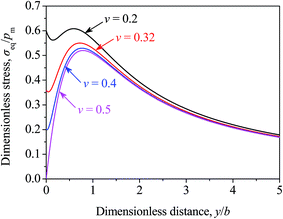 | ||
| Fig. 3 Dimensionless stress σeq/pm vs. the dimensionless distance y/b for various values of Poisson’s ratio ν. | ||
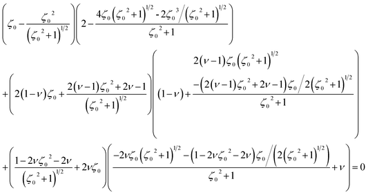
Because the equivalent Von Mises stress σeq is less than or equal to the yield strength Y of the coating material before the plasticity inception, the peak value (σeq/pm)max is equal to the value of Y/pm at the elastic terminus for the different values of Poisson’s ratio ν. In other words, the elastic–plastic transition first occurs at the dimensionless location (y/b)p for various Poisson’s ratios. Differentiating eqn (9) with respect to the variable y/b and letting the right-hand side equate to zero can get an implicit function of the dimensionless location ζ0 = (y/b)p of yielding inception versus Poisson’s ratio ν, which is expressed as
 | (10) |
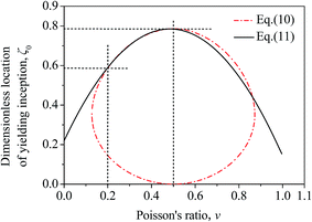
In order to practice a convenient discussion, eqn (10) could be simplified as a matching parabolic function within the scope of Poisson’s ratio by the function approximation technique, which is expressed as
| ζ0 = 0.2196 + 2.3349ν − 2.4105ν2 | (11) |
The error of the mean square introduced by eqn (11) is less than 0.53%. Fig. 4 presents the fitting result for the values of ν in the range of 0.2 to 0.5. Obviously, the approximation function eqn (11) shows a good consistency with eqn (10), in addition, the dimensionless location ζ0 of the elastic–plastic transition on the axis of symmetry performs approximate parabolic growth as ν increases. Hence, the lower the resistance to the compression of the coating materials, the more shallow the dimensionless location of the yielding inception along the y axis, and the higher the ratio of the yield strength over the maximum contact pressure.
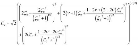
By substituting y/b with ζ0 in eqn (9), then combining eqn (2), (3) and (σeq/pm)max = Y/pm, the critical load Pc at the elastic–plastic transition of the compressed coating is obtained in the form of
 | (12) |
 | (13) |
By substituting eqn (11) into (13), the approximation function of eqn (13) is acquired using a numerical approaching method for the values of ν in the range of 0.2 to 0.5, which is written as
| Cν = 1.1637 + 2.9775ν − 2.9139ν2 | (14) |
The error of the mean square introduced by eqn (14) is less than 0.31%. Replacing P in eqn (3) and (4) with Pc in eqn (12) yields the critical half width bc and the critical interference ωc at the yielding inception of the coating material on its axis of symmetry, which are expressed as
 | (15) |
 | (16) |
The critical maximum contact pressure pmc at the elastic–plastic transition can be obtained by substituting eqn (12) and (15) into eqn (2), which is written as
| pmc = CνY | (17) |
Eqn (17) illustrates the physical meaning of the dimensionless parameter Cν, that is, it represents the ratio of the critical maximum contact pressure at the contact centre over the yield strength of the coating material. It is surprising to find that eqn (17) is quite consistent with the conclusions for a spherical contact with a rigid plane, where a Taylor series was adopted to derive the critical contact parameters of the elasticity terminus, and an approximately linear relation between the dimensionless yielding inception depth and Poisson’s ratio was obtained for the homogeneous sphere.46 Eqn (12), (15) and (16) separately give the critical expressions of load, half width and interference as coating yields along the axis of symmetry. It can be seen that such critical contact parameters are functions of the geometrical and mechanical properties of the loaded cylindrical coating.
3. Finite element model
3.1 Meshing and boundary conditions
When the coating thickness is thinner, the cylindrical substrate could deform largely under the vertical load of the contact flat, thus having a significant influence on the stress distribution in the coating that should be taken into account. Since the coating and substrate performance give discontinuous mechanical properties at their interface, the research of the coating/substrate composite should employ a finite element model based on numerical calculation. Fig. 5 presents a plane-strain model of the coated cylinder contacting a rigid flat using the commercial ABAQUS package (version 6.10) on the basis of an implicit integration algorithm, where only a quarter of the strain plane is considered due to axisymmetry. The quarter of a circle represents the cylindrical substrate, and the quarter of a ring represents the shelly coating, in addition the line represents the rigid flat. In order to accurately capture a high stress gradient near the contact zone in a relatively short computation time, the model is divided into four zones (see Fig. 5(a)) by three circular arcs, whose radii from the contact centre are 100 μm/[(R + t) μm], 300 μm/[(R + t) μm] and 1500 μm/[(R + t) μm], respectively. The first three zones have uniform mesh densities, whose typical sizes are 1 μm/[(R + t) μm], 5 μm/[(R + t) μm] and 25 μm/[(R + t) μm], respectively. However, the fourth zone displays a gradually coarser mesh with the increasing radius, among which the maximum size adjacent to the base of the substrate is approximately 0.1R, and a node is arranged at the bottom of the coating (see Fig. 5(b)). Moreover, the connected partitions have an approximately identical element at their junction so as to increase the convergence of the numerical simulations. A 4-node quadrilateral element (CPE4I) is used for both the coating and substrate. The flat is simulated by an analytical rigid model with no need of defining elements and material properties. The entire mesh consists of 39![[thin space (1/6-em)]](https://www.rsc.org/images/entities/char_2009.gif) 020–62
020–62![[thin space (1/6-em)]](https://www.rsc.org/images/entities/char_2009.gif) 056 elements, and 39
056 elements, and 39![[thin space (1/6-em)]](https://www.rsc.org/images/entities/char_2009.gif) 339–62
339–62![[thin space (1/6-em)]](https://www.rsc.org/images/entities/char_2009.gif) 492 nodes depending on the various t/R ratios of the coating thickness over the substrate radius. The boundary conditions are in agreement with those described in Section 2, that is to say, they contain the node constraints in both the vertical and radial directions at the base of composite system and in the radial direction on the axis of symmetry.
492 nodes depending on the various t/R ratios of the coating thickness over the substrate radius. The boundary conditions are in agreement with those described in Section 2, that is to say, they contain the node constraints in both the vertical and radial directions at the base of composite system and in the radial direction on the axis of symmetry.
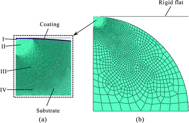 | ||
| Fig. 5 Finite element meshes of the coating/substrate system in (a) partial enlarged view and (b) global view. | ||
The coating and substrate are assumed to be linear and isotropic materials. The Von Mises yield criterion is used to detect the initiation of plastic deformation. A total of three analysis steps are defined throughout the simulation process. One surface-to-surface contact between the rigid flat and coating, which follows a finite sliding formulation, is applied in the initial step, so are the tie constraints imposed between connected zones as well as the coating and substrate. Normal loading is accomplished on the reference point of the rigid flat in the subsequent two load steps. To make the contact relationship begin smoothly, a very small value is applied in the first load step. The increment size and number of iterations in every load step are defined using the default settings of program.
The validity of the numerical model is verified by comparing the finite element results with the analytical Hertz solutions for the elastic contact between an uncoated cylinder and a rigid flat. The error of mean square between the critical loads calculated by Hertz model and finite element method, respectively is less than 0.6%. Proper convergence of the numerical solution is tested by refining the mesh size until further refinement has a negligible effect on the results, increasing individual quantities by at least one order of magnitude. The computation times for each run vary from about 1 min to 3 min on a 64 GB memory HP Z820 workstation with dual hexa-core 2.9 GHz CPU.
3.2 Results and discussion
The Von Mises stresses at the onset of the plastic yielding were calculated along the axis of symmetry of the cylindrical coating/substrate system for various mechanical parameters. Fig. 6 presents such distributions vs. a normalized distance y/t measured from the contact center, where a dashed line denotes the coating/substrate interface at y/t = 1. The specific simulation parameters are shown in Table 1, in which a third special case of coating material identical to that of the substrate is also presented for comparison. Simulation results show the critical load of the coating 1/substrate system at the yield inception is 7 kN, however the corresponding value of the coating 2/substrate system is about 6.4 kN. Furthermore, under the normal load of 7 kN, the Von Mises stresses of both coatings are separately 203 MPa and 274 MPa at the interface, but the corresponding values of both substrates are all 150 MPa. Consequently, for the two coated cases, both substrates yield first at the interface, but both coatings are far from their yield strengths. Besides, a discontinuity in the Von Mises stress distribution is clearly shown at the interface of two cylindrical coating/substrate composites, and the discontinuity is more pronounced for the higher mechanical properties of Eco = 391 GPa and Yco = 638 MPa. For the uniform material case, the normal load is selected to be the same as the upper threshold value for the coating 1/substrate system, i.e., 7 kN. Through simulation, the stress distribution along the axis of symmetry is continuous as would be expected, and the maximum stress is only about 145 MPa, which is below the yield strength of 150 MPa. Therefore, in spite of applying a higher critical load for both coated cylinders, the homogeneous one still undergoes a pure elastic deformation.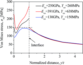 | ||
| Fig. 6 Equivalent Von Mises stress distribution along the axis of symmetry of a coated cylinder for various coating properties at t/R = 0.001. | ||
| Elasticity modulus E (GPa) | Yield strength Y (MPa) | Poisson’s ratio ν | Geometrical dimensions | |
|---|---|---|---|---|
| Substrate | 130 | 150 | 0.32 | R = 10 mm |
| Coating 1 | 250 | 260 | ||
| Coating 2 | 391 | 638 | t/R = 0.001 | |
| Coating 3 | 130 | 150 |
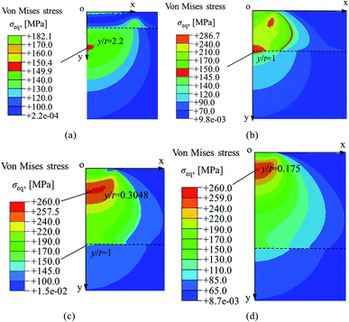
Fig. 7 presents the typical locations at the yield inception in the above cylindrical coating/substrate composites under different simulation parameters. For the mechanical properties of Eco = 250 GPa and Yco = 260 MPa, when the geometrical dimension is assigned as t/R = 0.001, the onset of plastic yielding first occurs within the substrate at the location of y/t = 2.2 > 1. Nevertheless, the maximum Von Mises stress in the coating is only about 182 MPa, being less than the yield strength of Yco = 260 MPa, as shown in Fig. 7(a). As the ratio of the coating thickness over the substrate radius is increased to t/R = 0.0105, the substrate and coating incipiently produce plastic yielding simultaneously, which occurs at the interface for the substrate, while that arises at y/t = 0.3048 for the coating (see Fig. 7(c)). However, at the ratio of t/R = 0.016, the coating first yields to plastic deformation at y/t = 0.175 < 1, but the maximum Von Mises stress of the substrate is far below its yield strength Ysu = 150 MPa (see Fig. 7(d)). In addition, for the coating properties of Eco = 391 GPa, Yco = 638 MPa and t/R = 0.005, as the substrate generates an initial yielding at the interface, the coating is under a pure elastic deformation in all regions (see Fig. 7(b)).
According to the above analysis, the homogeneous cylinder manifests a superior yielding resistance in comparison with both the coated ones. Besides, for the coating properties of Eco = 448 GPa, Yco = 836 MPa and t/R = 0.003, the substrate initially yields at the interface on the axis of symmetry, and the critical yielding load is about 6.4 kN. However, when the coating material acquires the property of substrate, the corresponding critical load and yield position are 8.02 kN and y/t = 0.9 respectively. Obviously, the dimensionless coordinate of the initial yield point moves from y/t < 1 to the interface with the substrate as the top properties of the homogeneous cylinder are replaced by the coating material, and the admissible load, resulting in a pure elastic deformation, becomes lower for the coated cylinder. Accordingly, it is observed that the coating weakens the yielding resistance of a cylindrical composite from the cases in the presence and absence of it. Actually, this degeneracy is mainly attributed to the additional stresses for relatively thin coatings induced by binding constraints at the coating/substrate interface, which could lower the critical load of a coated system and shift the first yielding location closer to the interface, in contrast to that without them.
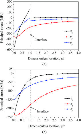
For the purpose of deeply understanding the action mechanism of the bond conditions imposed at the coating/substrate interface, Fig. 8 presents the principal stresses of both heterogeneous and homogeneous cylinders along their axis of symmetry for the properties described, i.e., Eco = 448 GPa, Yco = 836 MPa and t/R = 0.003 with the substrate nature unchanged. The normal loads applied in the two analyses are identical and equal to the critical value of the coated cylinder. As is known, the shear stress components are τxy = τxz = τyz = 0 for the axis of symmetry of the cylinder, and hence the corresponding normal stress components σx, σy and σz are three principal stresses. For the heterogeneous cylinder (Fig. 8(a)), the distributions of σx and σz show a clear discontinuity at y/t = 1. Moreover, the principal stress σx of the coating possesses a value of σx = 156 MPa, which is tensile, while that of substrate equals to −6.3 MPa becoming compressive. In the axial direction, the principal stress σz remains compressive at both sides of the interface, but its value jumps from −7.8 MPa to −58 MPa as y/t increases. Along the axis of symmetry, the principal stress σy is continuous and compressive with a value of −175 MPa at the interface. In the second case (Fig. 8(b)), all principal stresses are compressive and decrease monotonically to zero as y/t comes close to the higher end. At the interface, σx, σy and σz are continuous and their values are −35 MPa, −179 MPa, and −68 MPa respectively. It can be seen that for the principal stress σy, there is a negligible distinction at y/t = 1 for both cases, however, the principal stresses σx and σz of the coated cylinder are substantially different from those without the coating. Through a comparative study on the two systems in the presence and absence of the coating, the bonding conditions force both the coating and substrate to keep an equal radial displacement at the interface. However, it is difficult for the stiffer coating to follow an inward constriction of the more compliant substrate. Thus, the coating is stretched by the substrate and then reduces the compressive stress of the substrate from −35 MPa to −6.3 MPa at their interface. In the axial direction, both the coating and substrate maintain no deformation for the plane-strain model, so the principal stress σz = ν(σx + σy) according to Hooke’s law. It is not hard to find that decreases about ν times less than σx does. It is known that the Von Mises stress is proportional to the quadratic sum of σx − σy, σz − σy, σx − σz.
Nevertheless, as the discontinuity is produced at the interface, the difference of σx − σy increases from 144 MPa to 168.7 MPa, and σz − σy increases from 110.5 MPa to 117 MPa in the substrate. Since σx − σz = σx − νσx − νσy, so the increment of σx − σz is about (1 − ν) times to that of σx, namely, it increases from 33 MPa to 51.7 MPa. Hence, the Von Mises stress increases from 130 MPa to 150 MPa, with these differences of principal stresses increasing due to the bonding conditions at the substrate/coating interface, resulting in an additional increase of 20 MPa, as mentioned before. Furthermore, increasing Eco can enhance the interaction between the coating and the substrate at the interface, thus bringing about a higher level of additional stresses. As a result, the yielding resistance of the coated cylinder becomes even lower and the discontinuity at the interface is more pronounced. This phenomenon may explain some experimental observations of the delamination failure for relatively thin coatings. The stress discontinuity at the interface and the weakening effect of the coating/substrate system could also be observed in a coated sphere contacting a rigid flat,47,48 but the coated sphere expresses an equal stress distribution in the x-axis and z-axis directions at any y coordinate, i.e., σx = σz, which is different from the stress relation σz = ν(σx + σy) for the coated cylinder. Not only that, the coated sphere has the same stress–strain principle in planes containing y-axis due to the symmetry, but the coated cylinder performs the properties only in the cross-section.
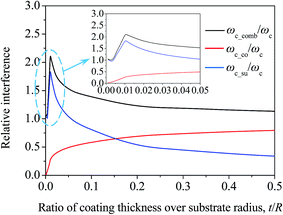
Under loading conditions, the total interference of the cylindrical coating/substrate composite consists of the individual interferences of the coating and substrate. Fig. 9 presents the dimensionless critical interference ωc_comb/ωc of the composite at yielding inception and the corresponding components ωc_co/ωc and ωc_su/ωc vs. the ratio of the coating thickness over the substrate radius, where ωc denotes the critical interference of a homogeneous cylinder with the substrate properties identical to those of the coating for a relative study. For the coating properties of Eco = 250 GPa, Yco = 260 MPa, ωc_su/ωc is much larger than ωc_co/ωc when t/R takes a small value, besides, ωc_comb/ωc and ωc_su/ωc increase first and then decrease but are always greater than 1 around t/R = 0.01. ωc_co/ωc, however, expresses monotonous growth from 0 with t/R increasing, which indicates the total interference of the coated cylinder is mainly attributed to the substrate deformation under a thinner coating. As t/R increases, ωc_su/ωc decreases continuously and ωc_co/ωc keeps rising, while at the ratio of t/R = 0.15, they have an identical value. However, when the t/R value is near the higher end of the scale, the relative value ωc_co/ωc of the coating approaches 1 and the relative value ωc_su/ωc of the substrate closes to 0, which reveals that the coating displacement displays as a dominant contributor to the system interference, while the contribution of the substrate is almost negligible at large t/R values. Therefore, the total interference ωc_comb of the coated cylinder is close to the critical value of the homogeneous cylinder when t/R is specified as a great value, that is, ωc_comb/ωc approaches 1 with increasing t/R.
Analogously, the cylindrical coating/substrate composite could be perceived as being composed of two springs in series in the load direction, both of which experience the overall load P, as shown in Fig. 10. When t/R is very small, the stiffness of the coating is much larger than that of the substrate, thus the system interference takes place primarily in the substrate. With the value of t/R becoming greater, the substrate stiffness becomes comparable to the coating stiffness, and the coating interference increases with the substrate contraction decreasing. When t/R has a large value, the coating stiffness is almost negligible in comparison to that of the substrate, so the coating compression serves as the dominant contributor to system interference.
 | ||
| Fig. 10 Spring series model of the cylindrical coating/substrate system under a normal contact load. | ||
4. Conclusions
The yielding inception of a coated cylinder contacting a rigid plane was studied by Hertz theory and finite element solutions. Some conclusions can be drawn as follows:(1) For super-thick coatings, the critical expressions of load, half width and interference were derived at the onset of plastic yielding along the axis of symmetry by a function approximation method. It can be seen that the geometrical and mechanical properties of the loaded cylindrical coating have important impacts on these critical contact parameters. Moreover, the smaller the Poisson’s ratio of the coating, the more shallow the dimensionless location of the yielding inception along the y axis, and the higher the ratio of the yield strength over the maximum contact pressure.
(2) For coatings with a thinner thickness, the Von Mises stress is discontinuous at the coating/substrate interface, and the discontinuity is more pronounced as the distinction of coating and substrate in their mechanical properties is increased. The initial yield position may be located either within the coating, in the substrate or at the interface, with the ratio of coating thickness over substrate radius changing.
(3) An upper elasticity modulus of the coating in comparison with that of the substrate can bring about an additional stress at the interface, thus lowering the yielding resistance of the coated cylinder.
(4) When t/R is very small, the total interference of the coated cylinder is mainly attributed to the substrate deformation. With the t/R ratio becomes greater, the coating compression becomes comparable to the substrate value. As t/R has larger values, the coating contraction serves as a dominant contributor to the composite interference.
(5) The coated cylinder expresses some similar behaviors as those of a coated sphere loaded by a rigid plane, but it gets the characteristics only in the cross-section, while the coated sphere possesses the corresponding properties in all symmetry planes containing the load direction.
Acknowledgements
The authors gratefully acknowledge the financial support from the National Natural Science Foundation of China (Grant no. 51202261 & 51475449), National Basic Research Program of China (973 Program) (Grant no. 2013CB632302) and State Key Laboratory for Mechanical Behavior of Materials Foundation (Grant no. 20141605).References
- M. Cui, J. Pu, J. Liang, L. Wang, G. Zhang and Q. Xue, RSC Adv., 2015, 5, 104829–104840 RSC.
- D. He, S. Zheng, J. Pu, G. Zhang and L. Hu, Tribol. Int., 2015, 82, 20–27 CrossRef CAS.
- D.-W. Kim and K.-W. Kim, Wear, 2014, 315, 95–102 CrossRef CAS.
- Q. Li, Z. Feng, L. Liu, J. Sun, Y. Qu, F. Li and M. An, RSC Adv., 2015, 5, 12025–12033 RSC.
- A. F. Rousseau, J. G. Partridge, E. L. H. Mayes, J. T. Toton, M. Kracica, D. G. McCulloch and E. D. Doyle, Surf. Coat. Technol., 2015, 272, 403–408 CrossRef CAS.
- K. R. Sriraman, P. Manimunda, R. R. Chromik and S. Yue, RSC Adv., 2016, 6, 17360–17372 RSC.
- Y. Ye, Y. Wang, H. Chen, J. Li, Y. Yao and C. Wang, Tribol. Int., 2015, 90, 362–371 CrossRef CAS.
- S. Zhou, H. Chen and L. Ma, Surf. Coat. Technol., 2014, 242, 177–182 CrossRef CAS.
- J. A. Brandao, J. H. O. Seabra and M. J. D. Castro, Measurement, 2016, 91, 479–487 CrossRef.
- T. H. Machado and K. L. Cavalca, Appl. Math. Model., 2016, 40, 9546–9564 CrossRef.
- G. M. Roach and L. L. Howell, J. Mech. Des., 2002, 124, 485–491 CrossRef.
- T. Liu, A. Jagota and C.-Y. Hui, Soft Matter, 2015, 11, 3844–3851 RSC.
- S. Saito, T. Ochiai, F. Yoshizawa and M. Dao, Sci. Rep., 2016, 6, 34063 CrossRef CAS PubMed.
- F. Jin and X. Guo, Int. J. Solids Struct., 2010, 47, 1508–1521 CrossRef CAS.
- O. I. Zhupanska and A. F. Ulitko, J. Mech. Phys. Solids, 2005, 53, 975–999 CrossRef.
- H. Qiu, D. A. Hills, D. Nowell and D. Dini, Int. J. Mech. Sci., 2008, 50, 293–298 CrossRef.
- D. Li, Y.-L. Han, Y.-M. Hu and R.-H. Wang, Power Eng., 2016, 175–180 CAS.
- C. Pereira, A. Ramalho and J. Ambrosio, Multibody Syst. Dyn., 2015, 35, 277–298 CrossRef.
- Y. P. Chiu and M. J. Hartnett, J. Tribol., 1987, 109, 479–485 CrossRef.
- S. C. Hunter, J. Appl. Mech., 1961, 28, 611–617 CrossRef CAS.
- T. Doca, F. M. Andrade Pires and J. M. A. Cesar de Sa, Int. J. Solids Struct., 2014, 51, 1697–1715 CrossRef.
- T. Doca and F. M. Andrade Pires, Tribol. Int., 2014, 79, 92–98 CrossRef.
- L. Chen and S. H. Chen, J. Appl. Phys., 2014, 116, 164701 CrossRef.
- P. Meijers, Appl. Sci. Res., 1968, 18, 353–383 CrossRef.
- S. Stupkiewicz, J. Lengiewicz, P. Sadowski and S. Kucharski, Tribol. Int., 2016, 93, 511–522 CrossRef.
- H. Proudhon, J. Savkova, S. Basseville, V. Guipont, M. Jeandin and G. Cailletaud, Wear, 2014, 311, 159–166 CrossRef CAS.
- T. Hong and N. Saka, Wear, 1991, 148, 47–68 CrossRef.
- H. Tian and N. Saka, Wear, 1991, 148, 261–285 CrossRef.
- P. K. Gupta and J. A. Walowit, J. Lubr. Technol., 1974, 96, 250–257 CrossRef.
- Y. Alinia, M. A. Guler and S. Adibnazari, Mech. Res. Commun., 2014, 55, 45–52 CrossRef.
- M. A. Guler and F. Erdogan, Int. J. Mech. Sci., 2007, 49, 161–182 CrossRef.
- Y. Alinia, M. A. Guler and S. Adibnazari, Mech. Mater., 2014, 68, 207–216 CrossRef.
- M. A. Guler, Y. Alinia and S. Adibnazari, Mech. Mater., 2013, 66, 134–159 CrossRef.
- S. J. Cole and R. S. Sayles, J. Tribol., 1992, 114, 334–340 CrossRef CAS.
- K. Komvopoulos, J. Tribol., 1989, 111, 430–439 CrossRef.
- J. Yang and K. Komvopoulos, J. Tribol., 2004, 126, 18–27 CrossRef.
- Z. Q. Gong and K. Komvopoulos, J. Tribol., 2004, 126, 655–663 CrossRef.
- R. K. Njiwa, R. Consiglio and J. von Stebut, Surf. Coat. Technol., 1998, 102, 138–147 CrossRef CAS.
- H. H. Bennani and J. Takadoum, Surf. Coat. Technol., 1999, 111, 80–85 CrossRef CAS.
- H. Djabella and R. D. Arnell, Thin Solid Films, 1993, 223, 87–97 CrossRef.
- R. Jahedi and S. Adibnazari, Int. J. Adv. Des. Manuf. Technol., 2015, 8, 1–12 Search PubMed.
- N. Demirhan and B. Kanber, Mech. Base. Des. Struct. Mach., 2013, 41, 383–398 CrossRef.
- M. A. Guler, Y. Alinia and S. Adibnazari, Int. J. Mech. Sci., 2012, 64, 62–81 CrossRef.
- K. L. Johnson, Contact Mechanics, Cambridge University Press, Cambridge, 1985, pp. 96–119 Search PubMed.
- C. M. Pereira, A. L. Ramalho and J. A. Ambrósio, Nonlinear Dyn., 2011, 63, 681–697 CrossRef.
- V. Brizmer, Y. Kligerman and I. Etsion, Int. J. Solids Struct., 2006, 43, 5736–5749 CrossRef.
- R. Goltsberg and I. Etsion, Wear, 2013, 308, 10–16 CrossRef CAS.
- R. Goltsberg, I. Etsion and G. Davidi, Wear, 2011, 271, 2968–2977 CrossRef CAS.
| This journal is © The Royal Society of Chemistry 2017 |

