
 Open Access Article
 This Open Access Article is licensed under a
 Creative Commons Attribution 3.0 Unported Licence
Synthesis of magnetic carbonaceous acids derived from hydrolysates of Jatropha hulls for catalytic biodiesel production†
Fan Zhang‡
 *ad,
Xiaofei Tian‡b,
Mazloom Shahac and
Wenjing Yanga
*ad,
Xiaofei Tian‡b,
Mazloom Shahac and
Wenjing Yanga
aBiomass Group, Key Laboratory of Tropical Plant Resources and Sustainable Use, Xishuangbanna Tropical Botanical Garden, Chinese Academy of Sciences, 88 Xuefulu, Kunming, Yunnan 650223, China. E-mail: zhangfan@xtbg.ac.cn; Web: http://www.tprsu.xtbg.ac.cn/ Fax: +86-871-65160916; Tel: +86-871-65180637
bSchool of Bioscience and Bioengineering, South China University of Technology, University Mega Centre, Guangzhou, Guangdong 510006, China. E-mail: xtien@scut.edu.cn
cDepartment of Chemistry, Women University of Azad Jammu and Kashmir, Bagh, 12500, Pakistan. E-mail: shahmazloom@gmail.com
dUniversity of Chinese Academy of Sciences, 19A Yuquan Road, Beijing, 100049, China
First published on 14th February 2017
Abstract
A series of magnetic carbonaceous acids (JHC-T1–T2-SO3H@Fe/Fe3O4) were synthesized by the assembly of nano-Fe3O4 magnetic cores (particle size < 20 nm) and carbon coatings derived from hydrolysates of Jatropha hulls. A magnetic JHC-12-600-SO3H@Fe/Fe3O4 catalyst with a total acid content of 2.69 mmol g−1 and a magnetic saturation of 40.3 A m2 kg−1 was successfully prepared via a sequence of hydrothermal precipitation, pyrolytic carbonization, and finally sulfonation with H2SO4. The catalyst was directly used for the production of biodiesel from Jatropha crude oil with an acid value (AV) of 17.2 mg KOH per g, and the optimized conditions (180 °C for 7.5 h with a molar ratio of methanol/oil of 18/1 and a catalyst loading of 7.5 wt%) were determined by single-factor tests. An average biodiesel yield of 95.9% was achieved with a recovery rate of 94.3% after 5 reaction cycles in a 5 L batch reactor for testing the feasibility of the catalyst for large-scale use. This study demonstrates an alternative green approach to fully utilizing waste biomass from energy plants in the catalytic synthesis of Jatropha biodiesel with high efficiency.
1. Introduction
Limitations in fossil oil reserves and global warming have become serious problems because of the growing global demand for energy and the accumulation of atmospheric CO2 by the combustion of fossil fuels.1,2 Biodiesel is considered to be an alternative liquid fuel owing to the advantage that it is clean and renewable.3,4 Because heterogeneous catalysts are easier to recover from the reaction system than liquid acid or alkaline catalysts,5 solid catalysts have been widely employed in the production of biodiesel. Solid basic catalysts including K/SiO2,6 CaO from eggshells7 and calcium-modified porous aluminosilicates8 have commonly been used in the production of biodiesel owing to their high performance in transesterification reactions of oils with a low acid value (AV). Natural Jatropha oil is a promising raw material for the production of biodiesel with suitable properties.9–11 However, it always has a high AV, which is caused by long-term storage.12,13 To avoid the direct use of basic catalysts, which would cause severe saponification of the reaction system during the transesterification of Jatropha oil, deoxygenation of fatty acids14 and transesterification with enzyme15 or solid acid catalysts16–18 are effective methods that have been widely employed in the production of biodiesel. However, deficiencies in these methods, such as the high cost of lipases, harsh deoxygenation conditions and incomplete separation of the catalyst particles from the products, remained and posed challenges to their further utilization in the large-scale production of biodiesel.14–18When catalyzing hydrolysis, esterification and dehydration reactions, solid acid catalysts, in particular sulfonated solid acid catalysts, exhibited excellent performance in the conversion of various alternative carbon resources, such as lignocellulosic biomass,19 sugars,20 and non-edible oils,21,22 for the purposes of producing fuels and high-value-added chemicals. For example, sulfated mesoporous niobium oxide (MNO-S) was developed as a catalyst for the production of 5-hydroxymethylfurfural (5-HMF). It catalyzed the hydrolysis and dehydration reactions of various disaccharide substrates and exhibited promising feasibility owing to a relatively high yield of 5-HMF and excellent recyclability.20
As sulfonated active carbon has been successfully employed in the catalytic production of biodiesel from crude Jatropha oil with a high AV of 12.7 mg KOH per g,22,23 the efficient recycling of solid carbons is of key importance for the purpose of reusing catalysts. Centrifugation and filtration methods have been commonly used, but both of them operated with low time or energy efficiency.22 The introduction of a magnetic field for the isolation of catalysts from the reaction system was a practical approach without intensive consumption of time or energy. Magnetic carbonaceous acids provided a convenient way of using a magnet for the isolation of catalysts. Novel carbon-based materials, including sulfonated magnetic lignin-derived amorphous carbon solid acids (MLC-SO3H),24 magnetic carbon nanotube arrays (sulfonated MCNAs)25 and magnetic carbonaceous acids,19,26,27 were synthesized and successfully used in catalyzing the dehydration of fructose and the hydrolysis of polysaccharides and cellulose, respectively. However, these reported magnetic carbonaceous acids were not adequate for employment in the production of biodiesel with high efficiency owing to their relatively low acidity or magnetism (Table 1).
| Catalyst | Raw materials | Preparation methods | Acidity (mmol g−1) | Magnetism (A m2 kg−1) | Catalytic reaction | Ref. |
|---|---|---|---|---|---|---|
| a By acid–base titration.b By NH3-TPD analysis.c Before sulfonation.d Calculated on the assumption that all the sulfur atoms were associated with sulfonic acid groups. | ||||||
| MLC-SO3H | Residue of enzymatic hydrolysis of corn stover and FeCl3 | Mixture: (300 rpm, 5 h); impregnation: (65 °C, 12 h); pyrolysis: (400 °C, 1 h); sulfonation: (150 °C, H2SO4, 10 h) | 1.95a | Dehydration of fructose to 5-hydroxymethylfurfural | 24 | |
| Sulfonated MCNAs | Xylene and ferrocene | Pyrolysis: (800 °C; the solution was injected by a syringe pump at a rate of 0.05 mL min−1 for 2 h with a flow rate of 60 sccm H2 and 400 sccm ar); sulfonation: (250 °C, H2SO4, 18 h) | 0.38b | 6.32c | Hydrolysis of polysaccharides in crop stalks | 25 |
| C–SO3H/Fe3O4 | Glucose and Fe3O4 | Agitation: (Fe3O4 and glucose solution, 100 °C, about 10 h); calcination: (700 °C, 1 h); sulfonation: (150 °C, H2SO4, 19 h) | 0.75a | 19.5 | Hydrolysis of cellulose to glucose | 19 |
| C–SO3H/Fe3O4@ | Glucose and FeCl3 | Hydrothermal carbonization: (glucose 180 °C, 14 h); desiccation: (40 °C, 12 h); sulfonation: (60 °C, H2SO4, 24 h) | 1.30a | 23 | Hydrolysis of cellulose to glucose | 26 |
| PMC-SO3H | Cellulose and Fe3O4 | Hydrothermal carbonization: (cellulose 250 °C, 14 h); desiccation: (80 °C, 12 h); agitation: [Fe(NO3)3 and NH3 solution, 250 °C, 24 h]; sulfonation: (80 °C, p-toluenesulfonic acid, 12 h); calcination: (400 °C, 12 h) | 0.64d | 4.71 | Hydrolysis of cellulose to glucose | 27 |
| SO3H–Fe/C | Glucose and FeCl3 | Hydrothermal precipitation: (180 °C, 14 h); pyrolysis: (700 °C, 1.5 h); sulfonation: (150 °C, H2SO4, 16 h) | 1.67b | 0.43 | — | 28 |
| AC-600-SO3H@Fe/C | Glucose and FeCl3 | Hydrothermal precipitation: (180 °C, 14 h); pyrolysis: (700 °C, 1.5 h); hydrothermal coating: (180 °C, 14 h); pyrolysis: (600 °C, 1.5 h); sulfonation: (150 °C, H2SO4, 16 h) | 2.79b | 14.4 | Transesterification of crude Jatropha oil with high AV | 28 |
| JHC-12-600-SO3H@Fe/Fe3O4 | Hydrolysates and Fe3O4 | Hydrothermal precipitation: (180 °C, 12 h); pyrolysis: (600 °C, 1.5 h); sulfonation: (180 °C, 12 h) | 2.69b | 40.3 | Transesterification of crude Jatropha oil with high AV (17.2 mg KOH per mg) | Present work |
In our previous work,28 an alternative magnetic AC-600-SO3H@Fe/C catalyst with high acidity and magnetic saturation was synthesized using glucose as the source of the carbon coating. With remarkably high efficiency in the transesterification of Jatropha oil and a high catalyst recovery rate, it was successfully employed for the production of Jatropha biodiesel. As the synthesis of the catalyst required edible sugar and complicated operations (Table 1), we therefore developed a method for preparing a series of magnetic carbonaceous acids via hydrothermal precipitation, pyrolytic carbonization and sulfonation using nano-Fe3O4 particles and hydrolysates of Jatropha hulls as alternative raw materials. The prepared magnetic carbonaceous acid that had the highest acidity and a relatively high magnetic saturation was selected and employed for the production of Jatropha biodiesel under conditions optimized by single-factor experiments.
2. Experiments
2.1. Materials
Nano-Fe3O4 particles (≥99.5%, particle size < 20 nm) were purchased from Aladdin Industrial Corporation (Shanghai, China). Analytical reagents, namely, concentrated H2SO4 (≥98.0%), Ca(OH)2 (≥95.0%), methanol (≥99.5%), KOH (≥85.0%), dehydrated ethanol (≥99.5%) and phenolphthalein were purchased from Xilong Chemical Factory Co., Ltd. (Shantou, Guangzhou, China). Standard materials of heptadecanoic acid methyl ester (C17:0) and other aliphatic acid methyl esters [palmitate (C16:0), palmitoleate (C16:1), stearate (C18:0), oleate (C18:1), linoleate (C18:2) and linolenate (C18:3)] (≥99.0%) were purchased from Sigma-Aldrich (Shanghai, China).Jatropha hulls were purchased from Yunnan Shenyu New Energy Co., Ltd. (Chuxiong, Yunnan, China). Before use, they were dried at 75 °C for 48 h and ground to pass through a sieve (80 mesh) using a pulverizer (9FC15, Xudong Machinery Manufacturing Co., Ltd, Leshan, Sichuan, China). Elemental analysis of the Jatropha hulls was performed using an elemental analyzer (Vario EL III CHNS, Elementar Analysensysteme GmbH, Hanau, Germany). The contents of C, H and O were 48.6%, 7.23% and 41.1% wt, respectively (Table 2). For acid hydrolysis, 15 g Jatropha hulls were loaded in a 300 mL ZrO2 reactor (FCFD03-30, Jianbang Chemical Mechanical Co. Ltd, Yantai, Shandong) containing 200 mL of 3 wt% concentrated H2SO4 solution. The suspension was thoroughly mixed by stirring at 300 rpm and heated to 150 °C. After 1.5 h, the reactor was cooled immediately. The residue of Jatropha hulls was removed by passing them through a filter (Merck Millipore, pore size 1.2 μm), and the hydrolysates were neutralized by adding Ca(OH)2 until the pH was 6.5–7.0. After filtration, the hydrolysates were further concentrated at 65 °C in a rotary evaporator (RE-52AA, Yancheng Instrument Co., Ltd, Shanghai, China). A concentration of soluble carbon of 61 g L−1 in the hydrolysates was finally achieved. Crude Jatropha oil (stored for six years) was obtained from Xishuangbanna Tropical Botanical Garden, Chinese Academy of Sciences.
| Wt% | Jatropha hulls | JHC-12-600@Fe/Fe3O4 | JHC-12-600-SO3H@Fe/Fe3O4 | JHC-12-600-SO3H@Fe/Fe3O4d |
|---|---|---|---|---|
| a Analyzed by Vario EL III CHNS elemental analyzer.b O (wt%) was calculated as 100 wt% – (C, H, N, S, and Fe) wt%.c Analyzed by ICP-OES.d JHC-12-600-SO3H@Fe/Fe3O4 catalyst after 5 cycles of use. | ||||
| Ca | 48.6 | 35.1 | 40.7 | 41.5 |
| Ha | 7.23 | 3.88 | 2.27 | 2.44 |
| Ob | 41.1 | 16.2 | 32.5 | — |
| Na | 2.67 | 1.67 | 1.11 | 0.82 |
| Sa | 0.173 | 0.250 | 3.62 | 2.37 |
| Fec | 0.227 | 42.9 | 19.8 | — |
2.2. Catalyst preparation
Firstly, 20 g nano-Fe3O4 particles (magnetic cores) were loaded into a 500 mL ZrO2 reactor (FCFD05-30, Jianbang Chemical Mechanical Co., Ltd, Yantai, Shandong, China) containing 0.4 L concentrated hydrolysates of Jatropha hulls. The mixture was maintained at 180 °C for different hydrothermal precipitation times (4, 8, 12, 16 and 20 h) while being stirred at 500 rpm. After the hydrothermal reaction, the solid product was recovered and washed with deionized water several times until a neutral solution was obtained. The neutralized solid product was saturated with dehydrated ethanol and freeze-dried at −47 °C in a freeze-dryer (PDU-1200, EYELA, Tokyo Rikakikai Co., Ltd, Japan) for 24 h. Carbonization of the magnetic carbonaceous precursor was performed in a tubular furnace (SGL-1100, Daheng Optics and Fine Mechanics Co., Ltd, Shanghai, China) with a nitrogen flow of 200 mL min−1. The temperatures in the oven reached 200, 400, 500, 600, 700 and 800 °C with a heating rate of 1.9–8.6 °C min−1 for 1.5 h. The products were designated as JHC-T1–T2@Fe/Fe3O4 (T1 is the hydrothermal precipitation time, T2 is the temperature of pyrolytic carbonization), respectively.A 10 g sample of JHC-T1–T2@Fe/Fe3O4 was added to a 500 mL flask containing 200 mL concentrated H2SO4. The mixture was maintained at 180 °C for 12 h under a nitrogen flow (100 mL min−1). The sulfonated JHC-T1–T2@Fe/Fe3O4 (JHC-T1–T2-SO3H@Fe/Fe3O4) that was obtained was washed with hot distilled water (70–80 °C) until the pH was 6.5–7. To remove the residual SO42−, the neutralized JHC-T1–T2-SO3H@Fe/Fe3O4 was hydrothermally treated with water at 180 °C for 3 h in the reactor. The treated JHC-T1–T2-SO3H@Fe/Fe3O4 was washed and freeze-dried. Before being used for the production of biodiesel, the prepared catalyst was ground and sieved through a 200 mesh screen.
2.3. Instrumentation
The total acid content (TAC) was measured by the temperature-programmed desorption (TPD) method using a chemisorption analyzer (Quantachrome Instruments, Boynton Beach, FL, USA). About 50–100 mg of the catalyst was used for TPD analysis. The program used for the reacting gas and sample temperature was as follows: standard gas (10% NH3 with 90% He, v/v, Yunnan Messer Co., Ltd, Kunming, China) was supplied for 60 min at 50 °C at a flow rate of 85 mL min−1 and then converted to He gas (99.999%, Yunnan Messer Co., Ltd, Kunming, China), and the temperature was gradually increased to 400 °C at a heating rate of 5 °C min−1 over 60–90 min. The total acid content was calculated using an external standard, which was calibrated against 0.5, 1, 1.5, and 2 mL of a standard gas (10% NH3 with 90% helium). Saturation magnetization (Ms) was measured using a vibrating sample magnetometer (VSM; Lake Shore 7407, Lake Shore Cryotronics, Inc., Westerville, OH, USA). Crystal structures were determined using an X-ray diffractometer (XRD; Rigaku Rotaflex RAD-C, Tokyo, Japan) equipped with a Cu Kα radiation source. All samples were equally loaded. The composition of metallic oxides in the catalyst was determined according to a pairwise comparison of diffraction patterns with standard records (Joint Committee on Powder Diffraction Standards, JCPDS: 89-2355, 06-0696, 72-1110 and 39-1346).29 The surface morphologies and microstructures of the catalysts and precursors were characterized using a scanning electron microscope (SEM; Zeiss EVO LS10, Cambridge, UK). The samples were loaded on copper mounts with double-sided electrically conductive adhesive carbon tape without gold coatings. Observations with the SEM were conducted using an accelerating voltage of 10.00 kV at a working distance of 15.5 mm. Transmission electron microscopy (TEM) images were recorded using a JEOL JEM-2010 microscope at an accelerating voltage of 200 kV. A suspension of the catalyst or precursor, which had been well dispersed in ethanol by ultrasonication, was dropped onto the copper grid and air-dried before being subjected to observation. Surface areas were selected and scanned by energy-dispersive X-ray spectrometry (EDX; Quanta 200, Hillsboro, OR, USA) for the determination of semi-quantitative elemental compositions (C, O, Fe and S). Functional groups were identified by Fourier transform infrared spectroscopy (FT-IR; Nicolet iS10, Thermo Fisher Scientific Co., Ltd, Waltham, MA, USA) within the spectral range of 400–4000 cm−1. A 0.05 g freeze-dried sample was blended with 0.5 g spectroscopic grade KBr in an agate mortar and then pressed into a disc. The KBr disc was scanned with a resolution in the range of 0.4–4 cm−1. The thermal stability of samples was determined using a thermogravimetric analyzer (TGA; TA Q500 HiRes, TA Instruments, New Castle, DE, USA). With 5 mg freeze-dried catalyst loaded in the TGA crucible, data were collected at temperatures rising from 40 to 800 °C at 5 °C min−1 under a helium gas atmosphere flowing at 50 mL min−1. The Brunauer–Emmett–Teller (BET) surface area and pore volume were measured by the nitrogen adsorption–desorption method using a TriStar II 3020 (Micromeritics Instrument Co., Ltd, Norcross, GA, USA). The samples were degassed at 120 °C for 3 h before analysis. The elemental composition was determined using an elemental analyzer (Vario EL III CHNS, Elementar Analysensysteme GmbH, Hanau, Germany). The catalysts were dissolved in an oxidizing agent containing 10% HCl and 3.5% HNO3 (w/w). The Fe content was determined by an inductively coupled plasma-optical emission spectrometer (ICP-OES; Optima 5300 DV, PerkinElmer Inc., Waltham, MA, USA).2.4. Biodiesel production and catalyst recovery
The catalytic esterification and transesterification of crude Jatropha oil were performed in a 50 mL batch reactor (YZPR-50, Yanzheng Experimental Instrument Co., Ltd, Shanghai, China) equipped with a quartz cup (Fig. 1). With a dead volume of 9.6 mL, the sealed reactor containing 18.6 g (0.02 mol) crude Jatropha oil, methanol (in a molar ratio to the oil of 6![[thin space (1/6-em)]](https://www.rsc.org/images/entities/char_2009.gif) :1–30:1) and the catalyst (2.5–12.5 wt% of the oil) was pressurized with nitrogen (2.0 MPa, 99.99%, Yunnan Messer Co., Ltd, Kunming, China) to avoid the evaporation of methanol at high temperatures. The reaction was conducted at 160–200 °C with a heating time of 25–35 min allowed before reaching the reaction temperature. After the reaction, the catalyst was isolated from the liquid using an NdFeB magnet (Fig. 1c) and subjected to direct reuse without any treatment.
:1–30:1) and the catalyst (2.5–12.5 wt% of the oil) was pressurized with nitrogen (2.0 MPa, 99.99%, Yunnan Messer Co., Ltd, Kunming, China) to avoid the evaporation of methanol at high temperatures. The reaction was conducted at 160–200 °C with a heating time of 25–35 min allowed before reaching the reaction temperature. After the reaction, the catalyst was isolated from the liquid using an NdFeB magnet (Fig. 1c) and subjected to direct reuse without any treatment.
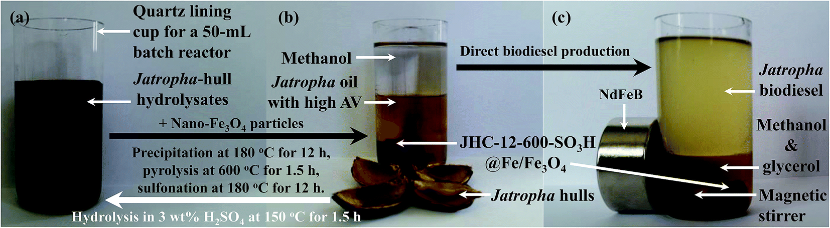 | ||
| Fig. 1 Images of (a) hydrolysates of Jatropha hulls, (b) a mixture of magnetic JHC-12-600-SO3H@Fe/Fe3O4 with Jatropha oil and methanol in a 50 mL batch reactor, and (c) the catalyst recovered by an NdFeB magnet from the synthesized Jatropha biodiesel. | ||
The large-scale production of Jatropha biodiesel in a 5 L batch reactor (FCFD05-30, Jianbang Chemical Mechanical Co., Ltd, Yantai, Shandong, China) with a dead volume of 36.7 mL (Fig. 2) was performed over the selected catalyst under conditions optimized via small-scale experiments. Before the reaction, an appropriate amount of the magnetic catalyst was first loaded on an NdFeB magnet fixed on the mixer shaft (Fig. 2b). Crude Jatropha oil (1.86 kg, 2 mol) and methanol were pumped into the reactor, which was sealed and then pressurized with nitrogen (99.999% purity, 2.0 MPa). High-speed stirring at 500 rpm was applied to homogenize the mixture with the catalyst. Then the reactor was heated to 180 °C within 60 min. After the reaction, the reactor was immediately cooled using circulating water for 0.5–1 h. The products were discharged slowly through the outlet valve (Fig. 2c), and the magnetic catalyst was collected on the mixer shaft attached to the NdFeB magnet for reuse.
 | ||
| Fig. 2 Images of (a) the 5 L batch reactor used for the production of biodiesel, (b) the magnetic JHC-12-600-SO3H@Fe/Fe3O4 catalyst attracted by the NdFeB magnet, which was attached to the mixer shaft, and (c) Jatropha biodiesel, glycerol and methanol pumped out of the reactor. | ||
After 3 cycles, the recycled catalyst was washed with an adequate amount of dehydrated ethanol 3–5 times and dried at 105 °C until a consistent weight was reached for calculation of the catalyst recovery rate.
| Catalyst recovery (wt%) = (mass of recovered catalyst, g)/(mass of fresh catalyst, g) × 100% | (1) |
2.5. Biodiesel assays
The AV (17.2 mg KOH per g) and saponification value (SV, 195.7 mg KOH per g) of the crude Jatropha oil samples were measured according to national standard protocols (GBT 5530-2005 and 5534-2008). The calculated average molecular weight of the crude oil was 942.9 g mol−1 according to the formula [M = (56.1 × 1000 × 3)/(SV − AV)].30The crude biodiesel that was produced was first clarified by being passed through a filter (pore size 0.22 μm, Merck Millipore). A Shimadzu gas chromatography (GC) system (GC-2014, Kyoto, Japan) equipped with a capillary column (Rtx-Wax, 30 m × 0.25 mm × 0.25 μm, Restek Corporation, Bellefonte, PA, USA) and a flame ionization detector (FID) was used for quantitative analysis of the yield of methyl esters in the product. Helium (99.999%) was used as the carrier gas at a flow rate of 1 mL min−1. A 10 μL sample was injected with a split ratio of 40:1. The temperatures of the column, injector and detector were maintained at 220, 260 and 280 °C, respectively.
The amount of methyl esters was calculated using C17:0 as an internal standard. The yield of biodiesel was calculated by the equation reported in our previous work.30
| Biodiesel yield (wt%) = {[(AC16:0/fC16:0 + AC16:1/fC16:1 + AC18:0/fC18:0 + AC18:1/fC18:1 + AC18:2/fC18:2 + AC18:3/fC18:3 + ACothers)/AC17:0] × weight of C17:0}/(weight of crude biodiesel) × 100% | (2) |
:0, 16:1, 18:0, 18:1, 18:2, and 18:3) is the peak area for the six standard methyl esters (C16:0, C16:1, C18:0, C18:1, C18:2, and C18:3), ACothers is the peak area for the other components except ACn, and fCn (1.014, 1.023, 1.076, 1.038, 1.019, and 0.926) is the relative response factor of Cn to that of C17:0.31
3. Results and discussion
3.1. Synthesis of magnetic carbonaceous acids
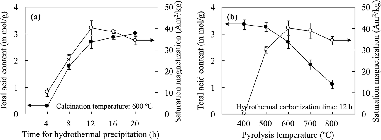 | ||
| Fig. 3 Changes in the total acid content and saturation magnetization of the prepared solid acids versus (a) the hydrothermal precipitation time and (b) the carbonization temperature used in synthesis of the catalyst precursor. | ||
With an increase in the hydrothermal precipitation time, the increase in the loading capacity of JHC-4-600@Fe/Fe3O4 for –SO3H groups was attributed to the growth in the carbonaceous surface areas of the magnetic cores via the continuous deposition of bulk carbon derived from the hydrolysates. SEM and TEM images (Fig. 4A-a and b) showed that a short precipitation time (4 h) led to a defective carbonaceous layer on the JHC-4-600@Fe/Fe3O4 precursor, which failed to protect the magnetic cores from corrosion by H2SO4 during sulfonation. EDX analysis (Fig. 4A-c) revealed that the carbon content was lower (6.60 wt%) in comparison to that of O (22.6 wt%) or Fe (70.8 wt%) on the surface of the precursor. After hydrothermal precipitation for 20 h, a complete carbonaceous coat was observed on JHC-20-600-SO3H@Fe/Fe3O4 (Fig. 4B-a and b). The C and S contents (wt%) that were determined significantly increased to 33.1 and 21.4, respectively, whereas the O and Fe contents decreased to 18.6 and 26.9, respectively (Fig. 4B-c). However, the overloaded carbonaceous coat decreased the relative content of magnetic Fe3O4 in the catalyst and thus led to a slight reduction in the Ms. In this study, 12 h was selected as the best hydrothermal precipitation time for preparing the catalyst in the following experiments.
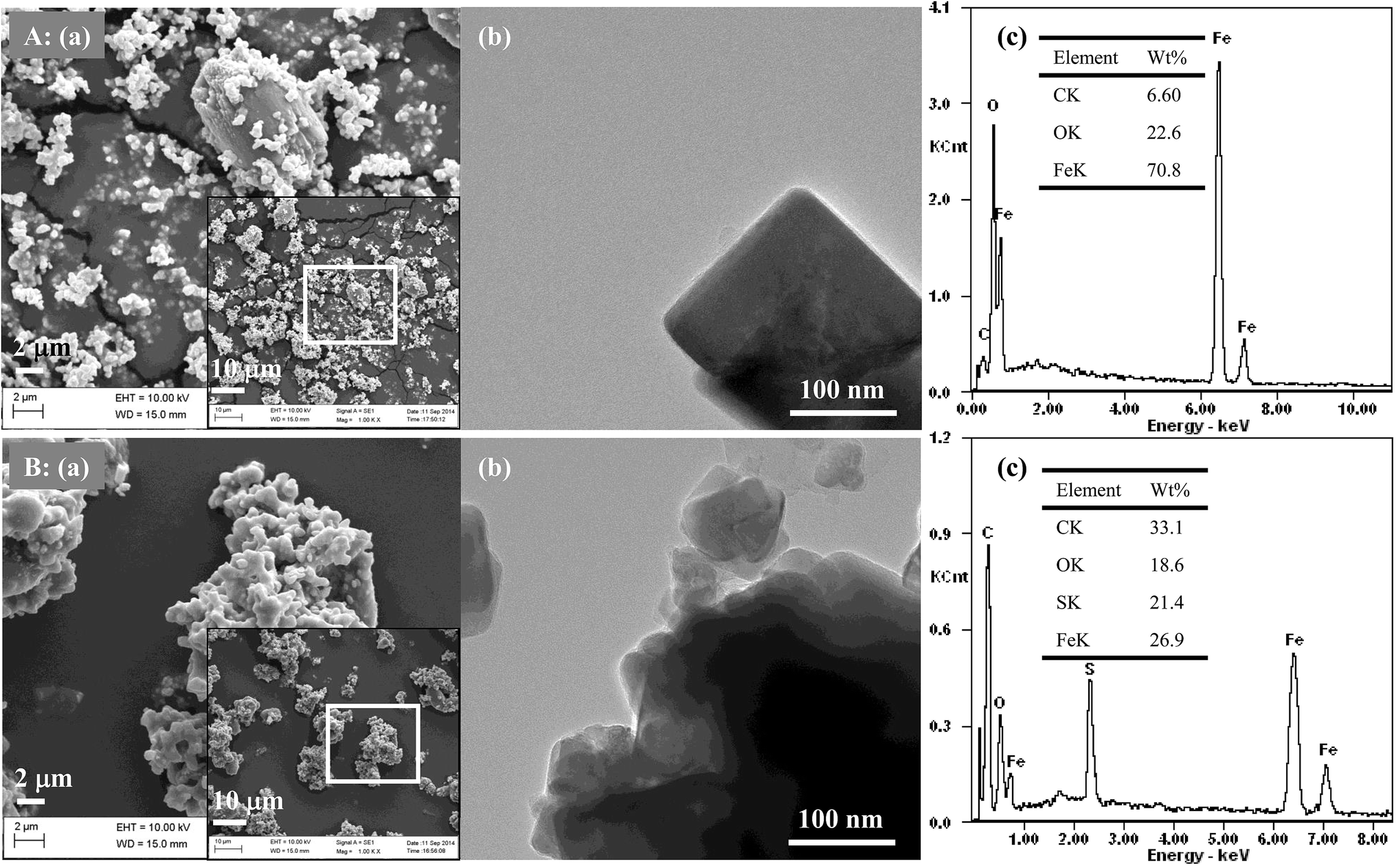 | ||
| Fig. 4 Observations of the surface morphologies and microstructures of the catalyst and catalyst precursor: (a) SEM images, (b) TEM images and (c) EDX spectra of (A) the magnetic JHC-4-600@Fe/Fe3O4 precursor and (B) the magnetic JHC-20-600-SO3H@Fe/Fe3O4 catalyst. | ||
The TAC was also affected by the carbonization temperature. In an analysis of the thermal stability of the JHC-12-200@Fe/Fe3O4 precursor, a weight loss (of about 6.06 wt%) was observed at 203–400 °C (Fig. S1†), where the loss of C, H and O elements (wt%: C 41.8 vs. 36.3, H 4.93 vs. 3.97, O 19.6 vs. 17.0) was confirmed by elemental analysis (Table S1†). However, the JHC-12-400@Fe/Fe3O4 and JHC-12-600@Fe/Fe3O4 precursors, which had similar elemental contents (Table S1,† wt%: C 36.3 vs. 35.1, H 3.97 vs. 3.88, O 17.0 vs. 16.2, Fe 40.7 vs. 42.9), possessed higher thermal stabilities up to a temperature of 400–601 °C. The weight loss (about 0.90 wt%, Fig. S2†) of the JHC-12-400@Fe/Fe3O4 precursor indicated the slight release of volatile compounds from the sample. The significant weight loss (about 3.06 wt%, Fig. S1†) between 601 and 800 °C could be due to the reaction C + Fe3O4 → Fe/Fe3C + CO2↑, with decreases in the C and O contents to 31.6 wt% and 13.4 wt%, respectively. In addition, XRD analysis confirmed the formation of Fe and Fe3C in the sample (Fig. 5A-a).28
 | ||
| Fig. 5 Characterization of (a) magnetic JHC-12-600@Fe/Fe3O4 precursor and (b) magnetic JHC-12-600-SO3H@Fe/Fe3O4 catalyst: (A) XRD, (B) VSM, (C) SEM, (D) FT-IR, and (E) NH3-TPD. | ||
Lower temperatures ensured a moderate content of hydrogen and oxygen atoms, which could be bonded by –SO3H groups on the surface of the precursor.32 With an excessive carbonization temperature, the loss of active bonding sites for the formation of layers of aromatic carbon on the surface of the precursor would significantly impair the efficiency of sulfonation.33 With an increase in the carbonization temperature from 400 to 800 °C, the TAC of the catalysts exhibited a dramatic decrease from 3.35 mmol g−1 to 1.12 mmol g−1. To achieve a balance between the Ms and TAC, 600 °C was selected as the optimized temperature for the carbonization of the precursor. Under these conditions, the TAC and Ms of the prepared JHC-12-600-SO3H@Fe/Fe3O4 were 2.69 mmol g−1 and 40.3 A m2 kg−1, respectively.
3.2. Characteristics of JHC-12-600@Fe/Fe3O4 and JHC-12-600-SO3H@Fe/Fe3O4
As magnetic Fe and Fe3C have a higher magnetic saturation than Fe3O4,37 JHC-12-600@Fe/Fe3O4 had a higher magnetic saturation of 94.3 A m2 kg−1 than that of carbonaceous Fe3O4 owing to the remarkable conversion of Fe3O4 into Fe and Fe3C.28 Owing to the loss of Fe3O4 and Fe3C, which was caused by dissolution in the concentrated H2SO4 solution, the Ms of JHC-12-600-SO3H@Fe/Fe3O4 declined to 40.3 A m2 kg−1 (Fig. 5B). However, the Ms of JHC-12-600-SO3H@Fe/Fe3O4 was still stronger than that of the AC-600-SO3H@Fe/C catalyst, which was only 14.4 A m2 kg−1.28
![[double bond, length as m-dash]](https://www.rsc.org/images/entities/char_e001.gif) O bonds at 3460 cm−1 and 1610 cm−1, respectively, which indicated the presence of –OH and –COOH groups in both JHC-12-600@Fe/Fe3O4 and JHC-12-600-SO3H@Fe/Fe3O4.24 The formation of Fe2O3 in JHC-12-600-SO3H@Fe/Fe3O4 was indicated by the Fe–O stretching vibration at 560 cm−1, which was further confirmed by the XRD analysis (Fig. 5A-b). Moreover, the CC stretching vibration at 1640 cm−1 and the C–O–S and OSO stretching vibrations at 1054–1060 and 1140–1180 cm−1 indicated the introduction of aromatic carbons and –SO3H groups, respectively, into the JHC-12-600-SO3H@Fe/Fe3O4 catalyst (Fig. 5D-b).20,28
O bonds at 3460 cm−1 and 1610 cm−1, respectively, which indicated the presence of –OH and –COOH groups in both JHC-12-600@Fe/Fe3O4 and JHC-12-600-SO3H@Fe/Fe3O4.24 The formation of Fe2O3 in JHC-12-600-SO3H@Fe/Fe3O4 was indicated by the Fe–O stretching vibration at 560 cm−1, which was further confirmed by the XRD analysis (Fig. 5A-b). Moreover, the CC stretching vibration at 1640 cm−1 and the C–O–S and OSO stretching vibrations at 1054–1060 and 1140–1180 cm−1 indicated the introduction of aromatic carbons and –SO3H groups, respectively, into the JHC-12-600-SO3H@Fe/Fe3O4 catalyst (Fig. 5D-b).20,28The content of sulfonic acid groups (–SO3H) in the JHC-12-600-SO3H@Fe/Fe3O4 catalyst was 1.13 mmol g−1, as calculated by elemental analysis, which showed a remarkable increase in the S content after sulfonation (Table 2). With the active –SO3H groups, the TAC of the catalyst reached 2.69 mmol g−1, as determined by NH3-TPD (Fig. 5E-b). The sulfonation treatment led to an increase of 1680% in the total acidity of JHC-12-600@Fe/Fe3O4, in which the original –OH and –COOH28 groups only displayed an acidity of 0.16 mmol g−1. With its high acidity, JHC-12-600-SO3H@Fe/Fe3O4 could be a favorable candidate as a catalyst for the production of biodiesel from Jatropha oil with a high AV.
3.3. Production of Jatropha biodiesel with JHC-12-600-SO3H@Fe/Fe3O4
According to previously reported conditions for the production of biodiesel (catalyst loading of 10 wt%, a molar ratio of methanol/oil of 24/1, a reaction temperature of 200 °C and a reaction time of 10 h),28 optimization of the catalyst dosage (2.5–12.5 wt% with respect to Jatropha oil), molar ratio of methanol to oil (6/1–30/1), reaction temperature (180–220 °C) and reaction time (2.5–12.5 h) for the production of Jatropha biodiesel was performed by single-factor tests. Each run was duplicated and the average values of the results were reported (Fig. 6). | ||
| Fig. 6 Single-factor optimization of production of biodiesel from Jatropha oil with the magnetic JHC-12-600-SO3H@Fe/Fe3O4 catalyst used for (a) 1 and (b) 2 cycles: (A) methanol/oil molar ratio, (B) catalyst loading, (C) reaction time, and (D) reaction temperature. | ||
When the catalyst was reused, the biodiesel yield increased from 33.0% to a maximum value of 88.5% with an increase in the MOR from 6/1 to 18/1 (Fig. 6A-b). However, increases in the MOR to 24/1 and further to 30/1 led to declines in the biodiesel yield to 85.5% and 82.1%, respectively. A similar effect of an increase in MORs on changes in the biodiesel yield was revealed using either fresh or recycled catalysts. As the pore structures in magnetic JHC-12-600-SO3H@Fe/Fe3O4 could be filled with methanol, the decline in the biodiesel yield was possibly due to a relatively low catalyst concentration that was caused by the higher MOR in the reaction system.28 Therefore, 18/1 was selected as the optimum MOR in the following experiments.
The catalyst loading with the fresh catalyst and with the recycled catalyst displayed remarkable differences in their effect on the biodiesel yield. With a loading of 2.5 wt% of the fresh catalyst and when the catalyst had been used once, the biodiesel yield was 66.5% and 34.6%, respectively (Fig. 6B-a and b). Increases in the catalyst loading to 5, 7.5, 10.0 and 12.5 wt% gradually narrowed the gap between the catalysts to 14.9%, 5.8%, 5.6% and 3.5%, respectively. To limit the cost by reducing the catalyst loading, 7.5 wt% was selected as the optimum level of catalyst loading.
When the catalyst was reused, a similar trend of an increase in the biodiesel yield from 61.5% to 92.5% was achieved as the temperature was increased from 160 to 180 °C (Fig. 6D-b). However, with further increases in the temperature to 190 °C and 200 °C, the biodiesel yield declined to 85.6% and 88.8%, respectively, but was slightly promoted at the higher reaction temperature of 200 °C via a change in the chemical equilibrium of the transesterification reactions.28 This indicated that firmly bonded active –SO3H groups on the fresh catalyst remained when the temperature was lower than 180 °C, at which sulfonation and hydrothermal pretreatment were performed on the catalyst.28 Higher temperatures could cause a slight deactivation of the catalyst by releasing part of the active groups. Therefore, 180 °C was selected as the optimum operating temperature of the catalyst.
3.4. Performance of magnetic JHC-12-600-SO3H@Fe/Fe3O4 catalyst in scaled-up applications
To evaluate the feasibility of using the magnetic JHC-12-600-SO3H@Fe/Fe3O4 catalyst for practical applications, the scaled-up production of Jatropha biodiesel was performed with an MOR of 18/1 and a catalyst loading of 7.5 wt% in a 5 L batch reactor (Fig. 2) at 180 °C for 7.5 h. Under optimal conditions, the JHC-12-600-SO3H@Fe/Fe3O4 catalyst was reused for 5 cycles with an average recovery rate of 94.3 ± 1.8 wt%. The biodiesel yield was 96.5%, 97.4%, 96.7%, 95.6% and 93.2%, respectively, whereas AV values of 0.25, 0.19, 0.27, 0.36 and 0.38 mg KOH per g were achieved after the first to fifth reaction cycles (Fig. 7). An average biodiesel yield of 95.9% and an AV of 0.29 mg KOH per g were achieved, which were slightly lower than the international standards for biodiesel products (96.5% and 0.5 mg KOH per g), respectively.38 The biodiesel yield reached 93.2% when the catalyst was reused for the fifth time. In comparison to 96.5%, which was the biodiesel yield with the new catalyst, the decline was considered to be due to the leaching of –SO3H groups from the catalyst. On the basis of the reduction in the sulfur content from 3.62 to 2.37 wt% (Table 2), the calculated leaching rate of –SO3H groups was 34.5% on the assumption that all the sulfur atoms were associated with sulfonic acid groups.27,28 | ||
| Fig. 7 Reuse of the JHC-12-600-SO3H@Fe/Fe3O4 catalyst for the production of Jatropha biodiesel in a 5 L batch reactor (reaction conditions: 180 °C for 7.5 h with a methanol/oil molar ratio of 18/1 and a catalyst loading of 7.5 wt%). | ||
The scaled-up experiments resulted in much higher biodiesel yields than those achieved in the 50 mL batch reactor (96.5% and 97.4% vs. 90.6% and 92.5% when the catalyst was used twice). This may have been caused by the difference in efficiency when mixing the catalysts with methanol and oil between agitator blades and magnetic stirrers (Fig. 2a vs. Fig. 1c). In comparison with the previous work,28 higher biodiesel yields were achieved (90.6% and 92.5% vs. 90.5% and 91.8% for 2 reaction cycles) when the JHC-12-600-SO3H@Fe/Fe3O4 catalyst was employed in the 50 mL batch reactor under much milder optimum conditions (vs. an MOR of 24/1 and a catalyst loading of 10 wt% at 200 °C for 10 h). In addition, the Ms of the JHC-12-600-SO3H@Fe/Fe3O4 catalyst was much higher than that of AC-600-SO3H@Fe/C (40.3 vs. 14.4 A m2 kg−1), as was previously reported. A catalyst with a strong Ms would be more suitable for use in a scaled-up reactor, because its strong attraction to an NdFeB magnet will prevent it from being carried out by the discharged biodiesel product (Fig. 2).
With high values of TAC and Ms, JHC-12-600-SO3H@Fe/Fe3O4 displayed better performance in the direct production of biodiesel (Table 1). Moreover, this also indicates that JHC-12-600-SO3H@Fe/Fe3O4 potentially has high efficiency in the esterification of free fatty acids at low temperatures (<100 °C).22 Therefore, it could be combined with solid bases in the production of biodiesel from crude oils with a high AV via a two-process conversion method.39
4. Conclusions
Magnetic carbonaceous acids derived from hydrolysates of Jatropha hulls were successfully synthesized. The JHC-12-600-SO3H@Fe/Fe3O4 catalyst, which contained coating layers of aromatic carbon bonded to abundant active groups (–OH, –COOH and –SO3H), possessed a high TAC and Ms (2.69 mmol g−1 and 40.3 A m2 kg−1). It displayed high activity and stability in the direct catalysis of the transesterification of Jatropha oil with a high AV (17.2 mg KOH per g) for the production of biodiesel. In a 5 L batch reactor, JHC-12-600-SO3H@Fe/Fe3O4 could be effectively recycled by a magnet for direct reuse. An average biodiesel yield of 95.9% was achieved after 5 reaction cycles with a catalyst recovery rate of 94.3%. Owing to their stable performance and multiple potential applications, the synthesis of magnetic carbonaceous acids derived from the hydrolysates of Jatropha hulls enabled the green and economic utilization of energy plant waste in the co-production of biodiesel products.Acknowledgements
The authors wish to acknowledge the financial support from the Youth Innovation Promotion Association CAS (No. 2017440) and Natural Science Foundation of China (No. 31400518).References
- M. Z. Jacobson, Energy Environ. Sci., 2009, 2, 148–173 CAS
.
- Z. Y. Hua, P. Q. Tan, X. Y. Yan and D. M. Lou, Energy, 2008, 33, 1654–1658 CrossRef
- L. Lin, C. S. Zhou, V. Saritporn, X. Q. Shen and M. D. Dong, Appl. Energy, 2011, 88, 1020–1031 CrossRef
- E. Lois, Fuel, 2007, 86, 1212–1213 CrossRef CAS
- Q. Kwok, B. Acheson, R. Turcotte, A. Janès and G. Marlair, J. Therm. Anal. Calorim., 2013, 111, 507–515 CrossRef CAS
- V. Mutreja, S. Singh, T. K. Minhas and A. Ali, RSC Adv., 2015, 5, 46890–46896 RSC
- S. B. Chavan, R. R. Kumbhar, D. Madhu, B. Singh and Y. C. Sharma, RSC Adv., 2015, 5, 63596–63604 RSC
- S. Sharma, D. Medpelli, S. J. Chen and D. K. Seo, RSC Adv., 2015, 5, 65454–65461 RSC
- J. C. Juan, D. A. Kartika, T. Y. Wu and T. Y. Y. Hin, Bioresour. Technol., 2011, 102, 452–460 CrossRef CAS PubMed
- H. C. Ong, A. S. Silitonga, H. H. Masjuki, T. M. I. Mahlia, W. T. Chong and M. H. Boosroh, Energy Convers. Manage., 2013, 73, 245–255 CrossRef CAS
- M. Y. Koh and T. I. M. Ghazi, Renewable Sustainable Energy Rev., 2011, 15, 2240–2251 CrossRef CAS
- S. Jain and M. P. Sharma, Energy, 2011, 36, 5409–5415 CrossRef CAS
- F. Zhang, Z. Fang and Y. T. Wang, Fuel, 2015, 150, 370–377 CrossRef CAS
- W. J. Li, Y. J. Gao, S. Y. Yao, D. Ma and N. Yan, Green Chem., 2015, 17, 4198–4205 RSC
- B. Norjannah, H. C. Ong, H. H. Masjuki, J. C. Juan and W. T. Chong, RSC Adv., 2016, 6, 60034–60055 RSC
- R. Hou, D. Zhang, X. Duan, X. Wang, S. Wang and Z. Sun, RSC Adv., 2016, 6, 81794–81801 RSC
- A. S. Badday, A. Z. Abdullah and K. T. Lee, Renewable Energy, 2013, 50, 427–432 CrossRef CAS
- J. M. Rafi, A. Rajashekar, M. Srinivas, B. V. S. K. Rao, R. B. N. Prasad and N. Lingaiah, RSC Adv., 2015, 5, 44550–44556 RSC
- T. C. Su, Z. Fang, F. Zhang, J. Luo and X. K. Li, Sci. Rep., 2015, 5, 17538–17542 CrossRef PubMed
- E. L. S. Ngee, Y. J. Gao, X. Chen, T. M. Lee, Z. G. Hu, D. Zhao and N. Yan, Ind. Eng. Chem. Res., 2014, 53, 14225–14233 CrossRef CAS
- H. C. Ong, A. S. Silitonga, H. H. Masjuki, T. M. I. Mahlia, W. T. Chong and M. H. Boosroh, Energy Convers. Manage., 2013, 73, 245–255 CrossRef CAS
- F. L. Pua, Z. Fang, S. Zakaria, C. H. Chia and F. Guo, Biotechnol. Biofuels, 2011, 4, 56–64 CrossRef PubMed
- H. Cui, S. Q. Turn and M. A. Reese, Catal. Today, 2009, 139, 274–279 CrossRef CAS
- L. Hu, X. Tang, Z. Wu, L. Lin, J. Xu, N. Xu and B. Dai, Chem. Eng. J., 2015, 263, 299–308 CrossRef CAS
- Z. Liu, X. Fu, S. Tang, Y. Cheng, L. Zhu, L. Xing, J. Wang and L. Xue, Catal. Commun., 2014, 56, 1–4 CrossRef CAS
- C. Zhang, H. Wang, F. Liu, L. Wang and H. He, Cellulose, 2013, 20, 127–134 CrossRef CAS
- H. X. Guo, Y. F. Lian, L. L. Yan, X. H. Qi and R. L. Smith Jr, Green Chem., 2013, 15, 2167–2174 RSC
- F. Zhang, Z. Fang and Y. T. Wang, Appl. Energy, 2015, 155, 637–647 CrossRef CAS
- K. Nakajima and M. Hara, J. Am. Ceram. Soc., 2007, 90, 3725–3734 CAS
- F. Zhang, X. H. Wu, M. Yao, Z. Fang and Y. T. Wang, Green Chem., 2016, 18, 3302–3314 RSC
- B. J. Xue, J. Luo, F. Zhang and Z. Fang, Energy, 2014, 68, 584–591 CrossRef CAS
- J. M. Anderson, R. L. Johnson, K. Schmidt-Rohr and B. H. Shanks, Carbon, 2014, 74, 333–345 CrossRef CAS
- L. Wang, X. Dong, H. Jiang, G. Li and M. Zhang, Bioresour. Technol., 2014, 158, 392–395 CrossRef CAS PubMed
- M. C. Pereira, F. S. Coelho, C. C. Nascentes, J. D. Fabris, M. H. Araújo, K. Sapag, L. C. A. Oliveira and R. M. Lago, Chemosphere, 2010, 81, 7–12 CrossRef CAS PubMed
- Y. Fei and E. Brosh, Earth Planet. Sci. Lett., 2014, 408, 155–162 CrossRef CAS
- F. A. Dawodu, O. Ayodele, J. Xin, S. Zhang and D. Yan, Appl. Energy, 2014, 114, 819–826 CrossRef CAS
- R. López de Arroyabe Loyo, S. I. Nikitenko, A. C. Scheinost and M. Simonoff, Environ. Sci. Technol., 2008, 42, 2451–2456 CrossRef
- M. Oguma, Y. J. Lee and S. Goto, Int. J. Automot. Tech., 2012, 13, 33–41 CrossRef
- P. M. Guo, F. H. Huang, M. M. Zheng, W. L. Li and Q. D. Huang, J. Am. Oil Chem. Soc., 2012, 89, 925–933 CrossRef CAS
Footnotes |
| † Electronic supplementary information (ESI) available. See DOI: 10.1039/c6ra28796d |
| ‡ Co-first authors. |
| This journal is © The Royal Society of Chemistry 2017 |