DOI:
10.1039/C6RA28499J
(Paper)
RSC Adv., 2017,
7, 9958-9963
Charge storage mechanisms of electrospun Mn3O4 nanofibres for high-performance supercapacitors†
Received
20th December 2016
, Accepted 26th January 2017
First published on 3rd February 2017
Abstract
Mixed oxidation states of manganese oxides are widely used as the electrodes in supercapacitors due to their high theoretical pseudocapacitances. However, their charge storage mechanisms are not yet fully understood. In this work, the charge storage mechanism of Mn3O4 or Mn2+(Mn3+)2O4 nanofibres was investigated using a synchrotron-based X-ray absorption spectroscopy (XAS) technique and an in situ electrochemical quartz crystal microbalance (EQCM). The average oxidation state of the Mn in the as-synthesized Mn3O4 is +2.67. After the first charge, the average oxidation states of Mn at the positive and negative electrodes are +2.61 and +2.38, respectively. The significant change in the oxidation state of Mn at the negative electrode is due to phase transformation of Mn3O4 to NaδMnOx·nH2O. Meanwhile, the charge storage mechanism at the positive electrode mainly involves the adsorption of counter ions or solvated SO42−. After the first discharge, the calculated Mn average oxidation numbers are +2.51 and +2.53 at the positive and negative electrodes, respectively. At the negative electrode, the solvated Na+ is desorbed from the electrode surface. At the same time, the solvated SO42− is desorbed from the positive electrode. The mass change of solvated Na+ during charging/discharging is ca. 80 ng per cm2 of the Mn3O4 electrode. A symmetric supercapacitor constructed from Mn3O4 nanofibres in 0.5 M Na2SO4 provides a working potential of 1.8 V, a specific energy of 37.4 W h kg−1 and a maximum specific power of 11.1 kW kg−1 with 98% capacity retention over 4500 cycles. The understanding of the charge storage mechanism of the mixed oxidation states of Mn2+(Mn3+)2O4 presented in this work could lead to further development of metal oxide-based pseudocapacitors.
Introduction
Supercapacitors have higher specific power (2–10 kW kg−1)1 than batteries (0.5–1 kW kg−1)1 and higher specific energy (5–10 W h kg−1)2 than conventional capacitors (0.01–0.05 W h kg−1).3 Their charge storage mechanisms are based on two phenomena, namely electrochemical double layer capacitance (EDLC) or physisorption of solvated ions on the supercapacitor electrodes, and pseudocapacitance or surface redox reactions. Carbon-based materials, e.g. activated carbon, carbon aerogel, graphene, carbon nanotubes and carbon onions, are extensively used as the electrode materials of electrochemical double layer capacitors.2,4–6 On the other hand, transition metal oxides, e.g. RuO2, NiO, Co3O4, MnO2 and Mn3O4, are widely used as active materials for pseudocapacitor electrodes.7–12 Among all metal oxides, manganese oxides are widely employed as pseudocapacitor electrodes because of their relatively low cost, low toxicity, high theoretical capacitance,13 and environmental compatibility.14 A number of manganese oxide structures including MnO, Mn3O4, Mn2O3, and MnO2 have been used for high-performance supercapacitors.13,15–17
Among all structures, Mn3O4 with a normal spinel structure with Mn2+ in tetrahedral units and Mn3+ in octahedral units18 with a formula structure of Mn2+(Mn3+)2O4 (ref. 19) provides high pseudocapacitance. Previously, Mn3O4-anchored graphene sheets produced by a microwave hydrothermal method have exhibited a specific capacitance (SC) of 70 F g−1 at 0.2 A g−1 in 1 M Na2SO4.20 A graphene-supported Mn3O4 nanocomposite synthesized by a precipitation method gives a SC of 61 F g−1 at 0.1 A g−1 in 1 M K2SO4.21 Mn3O4 nanoparticles (NPs) prepared by ultrasonication and hydrolysation provide a SC of 261 F g−1 at 0.4 A g−1 in 1 M Na2SO4 (ref. 22) and those produced by chemical precipitation show a SC of 322 F g−1 at 0.5 mA cm−2 in 1 M Na2SO4.23 More interestingly, 1D nanofibres of mixed Mn2O3 and Mn3O4 produced by an electrospinning process, which is a simple, efficient, and reproducible method,24 exhibit a SC of 360.7 F g−1 at 1 A g−1 in 0.5 M Na2SO4.25 This indicates that 1D nanofibres can enhance both the ion transport pathways and the surface area, increasing the contact area between the electrolyte ions and the surface of the electrodes.25 The porosity of the nanofibers also plays an important role in the charge storage performance of the supercapacitors.26,27 Micropores can help increase the electrochemical double layer capacitance due to their high surface area, while mesopores can enhance electrolyte ion transportation. For example, MnOx nanofibers with a pore size of around 10–30 nm provide very good electrolyte diffusion.28
However, the charge storage mechanism of Mn3O4 is unclear and rather complex.8,29,30 In this work, we have investigated the charge storage mechanism of Mn3O4 nanofibres using high-resolution synchrotron-based X-ray absorption (XAS) and electrochemical quartz crystal microbalance (EQCM) techniques. The results here showed that Mn3O4 nanofibres produced by an electrospinning process using 10 wt% manganese acetate (Mn(OAc)2) in polyacrylonitrile (PAN) solution provide higher SCs than other samples. The charge storage mechanism of the Mn3O4 nanofibres investigated by XAS involves a phase transformation of Mn3O4 to NaδMnOx·nH2O during the first charge. Subsequently, the mechanism is based on surface redox reactions. The mass change of solvated Na+ during charging/discharging is ca. 80 ng per cm2 of the Mn3O4 electrode.
Experimental section
Electrospinning of manganese oxide nanofibres
Firstly, 1 g of PAN (Mw = 150![[thin space (1/6-em)]](https://www.rsc.org/images/entities/char_2009.gif) 000, Aldrich) was dissolved in 10 ml of dimethylformamide (DMF) (Qrec, 99.8%) at 60 °C under stirring and then cooled down to room temperature. Then, 0.052 g of manganese acetate tetrahydrate (Mn(OAc2)·4H2O) (Acros, 99+%) was added into the PAN solution. The PAN/Mn(OAc2) solution was subsequently put into a syringe, and the distance between the syringe tip and an aluminium foil collector was fixed at 10 cm. The electrospinning process was subsequently operated at a feed flow rate of 2 ml h−1 and the applied potential was finely tuned to 15 kV. The Mn(OAc2) content (0.11 g for 10 wt%, 0.25 g for 20 wt%, 0.42 g for 30 wt%, and 0.56 g for 36 wt%) was also varied to finely tune the homogeneous electrospun nanofibres. Finally, the as-spun nanofibres were dried at ambient temperature for 24 h and calcined at 500 °C with a heating rate of 5 °C min−1 for 2 h.
000, Aldrich) was dissolved in 10 ml of dimethylformamide (DMF) (Qrec, 99.8%) at 60 °C under stirring and then cooled down to room temperature. Then, 0.052 g of manganese acetate tetrahydrate (Mn(OAc2)·4H2O) (Acros, 99+%) was added into the PAN solution. The PAN/Mn(OAc2) solution was subsequently put into a syringe, and the distance between the syringe tip and an aluminium foil collector was fixed at 10 cm. The electrospinning process was subsequently operated at a feed flow rate of 2 ml h−1 and the applied potential was finely tuned to 15 kV. The Mn(OAc2) content (0.11 g for 10 wt%, 0.25 g for 20 wt%, 0.42 g for 30 wt%, and 0.56 g for 36 wt%) was also varied to finely tune the homogeneous electrospun nanofibres. Finally, the as-spun nanofibres were dried at ambient temperature for 24 h and calcined at 500 °C with a heating rate of 5 °C min−1 for 2 h.
Characterization of the electrospun nanofibres
The morphologies of the as-electrospun nanofibres and as-calcined manganese oxide nanofibres were characterized by SEM-EDX (SEM-EDX, Philips XL30) and TEM (TEM, Hitachi HT7700). The crystalline structure of the as-calcined nanofibres was characterized by XRD (XRD PHILIPS, X'Pert-MPD 40 kV 35 mA, Cu Kα 1.54056 Å) with a 2θ range of 10–80° and a step size of 0.02° s−1. The electronic structure of the nanofibres was characterized by X-ray absorption spectroscopy (XAS), at the Synchrotron Light Research Institute (Thai Public Organization). More details on the XAS measurement procedures can be found in our previous report.31
Electrochemical characterization
The electrochemical properties of the nanofibres were tested by cyclic voltammetry (CV), galvanostatic charge/discharge (GCD), and electrochemical impedance spectroscopy (EIS) in 0.5 M Na2SO4 electrolyte using a Metrohm AUTOLAB potentiostat (PGSTAT 302N). Platinum wire and Ag/AgCl (3 M KCl) were used as a counter electrode and a reference electrode, respectively. In a two-electrode system, GCD was measured using a NEWARE battery tester (GELON LIB., CTS 20V-5A-GGS). The as-calcined MnOx nanofibres were mixed with a conductive additive (carbon black, CB) and an adhesive binder (polyvinylidene fluoride, PVDF) at a weight ratio of 6:3:1 (MnOx:CB:PVDF) in N-methyl-2-pyrrolidone (NMP). The mixture was then spray-coated onto functionalized-carbon fibre paper with dimensions of 1 × 1 cm2 for the three-electrode system and a circle with a diameter of 1.58 cm for the two-electrode system. The mass loading was about 2 mg cm−2 for each electrode. The electrode was dried at 80 °C for 24 h. The hydrolysed polyethylene (PE) separator was soaked in 0.5 M Na2SO4 and inserted between the two working electrodes in a coin case (2016 type). Finally, the symmetric supercapacitor device was fabricated using a hydraulic compression machine at 800 psi. The in situ charge storage mechanism of the MnOx nanofibre electrodes was characterized using an electrochemical quartz crystal microbalance (EQCM) with Ag/AgCl (3 M KCl) gel as the reference electrode, Au wire as the counter electrode, and about 0.6–0.7 mg cm−2 of the sample coated on an Au support (0.67 cm in diameter).
Results and discussion
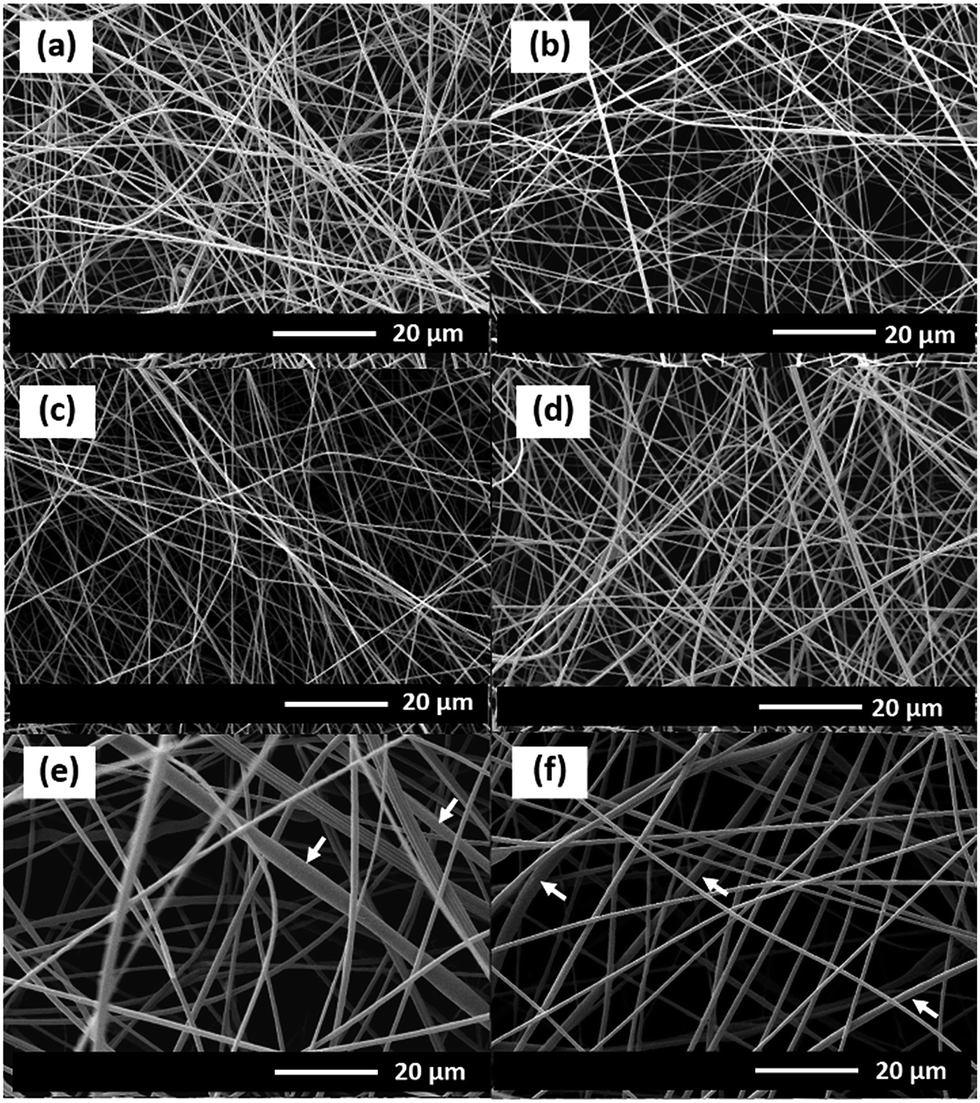
The morphologies of the as-electrospun PAN/Mn(OAc)2 nanofibres with different Mn(OAc)2 contents in PAN are shown in Fig. 1. The diameters of the as-electrospun nanofibres are about 400–500, 430–500, 500–600, 900–1800, and 900–1700 nm for 5, 10, 20, 30 and 36 wt% Mn(OAc)2, respectively.
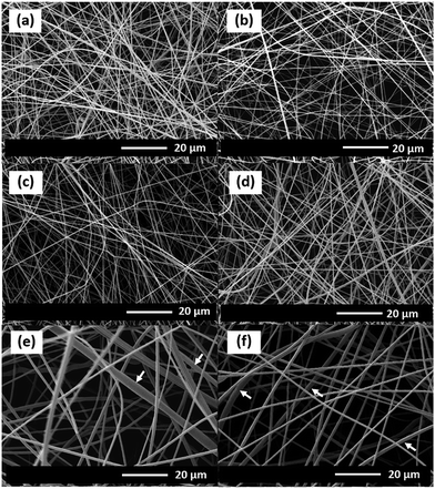 |
| | Fig. 1 SEM images of the as-electrospun PAN nanofibres at different Mn(OAc)2 loading contents: (a) 0, (b) 5, (c) 10, (d) 20, (e) 30, and (f) 36 wt%. | |
Fig. 2 shows the morphology of the MnOx nanofibres after calcining at 500 °C for 2 h. After the removal of PAN, the diameter of the as-calcined MnOx nanofibres is reduced. With increasing Mn(OAc)2 concentrations, the as-calcined MnOx formed larger nanofibres. The diameters of the MnOx nanofibres are 60–125, 60–200, 150–250, 300–600, and 300–600 nm for 5, 10, 20, 30 and 36 wt% Mn(OAc)2, respectively. The presence of Mn and O in the as-obtained nanofibres was confirmed by EDX (Fig. 2f). In addition, it is clearly seen from the TEM images that the MnOx nanofibres are formed from connected MnOx particles with open pores in the structure. Note that the PAN/Mn(OAc)2 fibres with rather large diameters cannot be dispersed in solvents and so are not suitable for TEM measurements.
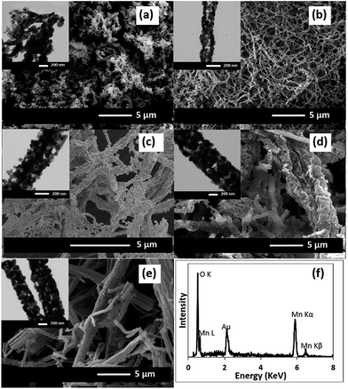 |
| | Fig. 2 SEM and TEM images of the MnOx nanofibres formed with different Mn(OAc)2 concentrations after calcining at 500 °C: (a) 5, (b) 10, (c) 20, (d) 30, and (e) 36 wt%. (f) The EDX spectrum of the MnOx nanofibres produced using 36 wt% Mn(OAc)2. | |
Fig. 3 shows the XRD patterns of the as-calcined MnOx nanofibres. The XRD patterns of the MnOx produced using 5–20 wt% Mn(OAc)2 are assigned to Mn3O4 (JCPDS 24-0734).25 In addition, the XRD patterns of the MnOx prepared using 30 and 36 wt% Mn(OAc)2 show mixed crystalline phases of Mn3O4 and Mn2O3 (JCPDS 073-1826).25 The Mn3O4 and Mn2O3 crystallite sizes are estimated using Scherrer's equation from the (211) and (222) planes, respectively. The Mn3O4 crystallite sizes are 13.3, 30.7, 42.3, 35.4 and 36.9 nm at 5, 10, 20, 30 and 36 wt% Mn(OAc)2, respectively. Meanwhile, the Mn2O3 crystallite sizes are 30.5 and 30.9 nm at 30 and 36 wt% Mn(OAc)2, respectively. Note that the Mn2O3 phase is easily removed by calcination at high temperature (see Fig. S1†). The formation of Mn3O4 occurs via reactions (1) and (2):24
| | |
Mn(CH3COO)2·4H2O → Mn(OH)(CH3COO) + 3H2O + CH3COOH
| (1) |
| | |
3Mn(OH)(CH3COO) → Mn3O4 + 2CO2 + CO + 3CH4
| (2) |
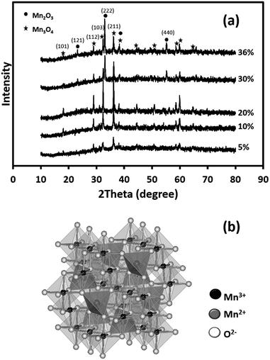 |
| | Fig. 3 (a) XRD patterns of the as-calcined MnOx nanofibres electrospun at different Mn(OAc)2 loading contents at 15 kV and (b) a crystal structure model of spinel Mn3O4. | |
Intermediate reactions are proposed as shown in reactions (3) and (4):32
| | |
2Mn(OH)(CH3COO) → Mn2O3 + CO2 + CO + 2CH4
| (3) |
Fig. 4 shows the electrochemical properties of the as-calcined MnOx nanofibres produced using different Mn(OAc)2 contents. From the CV curves (Fig. 4a), the Mn3O4 nanofibres electrospun at 10 wt% Mn(OAc)2 exhibit the largest area under the curve, leading to the highest capacitance. The SCs of the symmetric Mn3O4 nanofibre supercapacitor at scan rates of 10, 20, 50, 70, and 100 mV s−1 are 161, 154, 130, 115, and 98 F g−1, respectively. The GCD result in Fig. 4b is in good agreement with the CV result. The working potential of the electrode excluding iR drop is ca. 0.9 V vs. Ag/AgCl. The Mn3O4 nanofibres produced with 10 wt% Mn(OAc)2 content exhibit the highest capacitance because of their high surface area and 3D porous structure, which enhances the contact area between the electrode and the electrolyte,25 and their small crystallite size, which can enhance charge transport.33 Meanwhile, the Mn3O4 nanofibres electrospun at 20 wt% Mn(OAc)2 show the lowest capacitance due to large crystallite size, which leads to poor charge transport. As the conductivity of Mn3O4 is relatively higher than that of Mn2O3,25 the Mn3O4 nanofibres produced at 10 wt% Mn(OAc)2 provide a higher SC than the mixed Mn3O4 and Mn2O3 nanofibres electrospun at 30–36 wt% Mn(OAc)2. The specific and areal capacitances of the Mn3O4 electrodes at different applied currents in 0.5 M Na2SO4 are shown in Fig. 4c and d, respectively. The charge storage performance of the Mn3O4 electrodes is under the diffusion limit since their capacitances decrease with increasing applied currents.
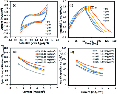 |
| | Fig. 4 (a) Cyclic voltammograms at a scan rate of 10 mV s−1, (b) galvanostatic charge–discharge curves at 1.25 mA cm−2, (c) the specific capacitance vs. applied current, and (d) the areal capacitances vs. applied current of the half-cell Mn3O4 electrodes in 0.5 M Na2SO4 electrolyte. | |
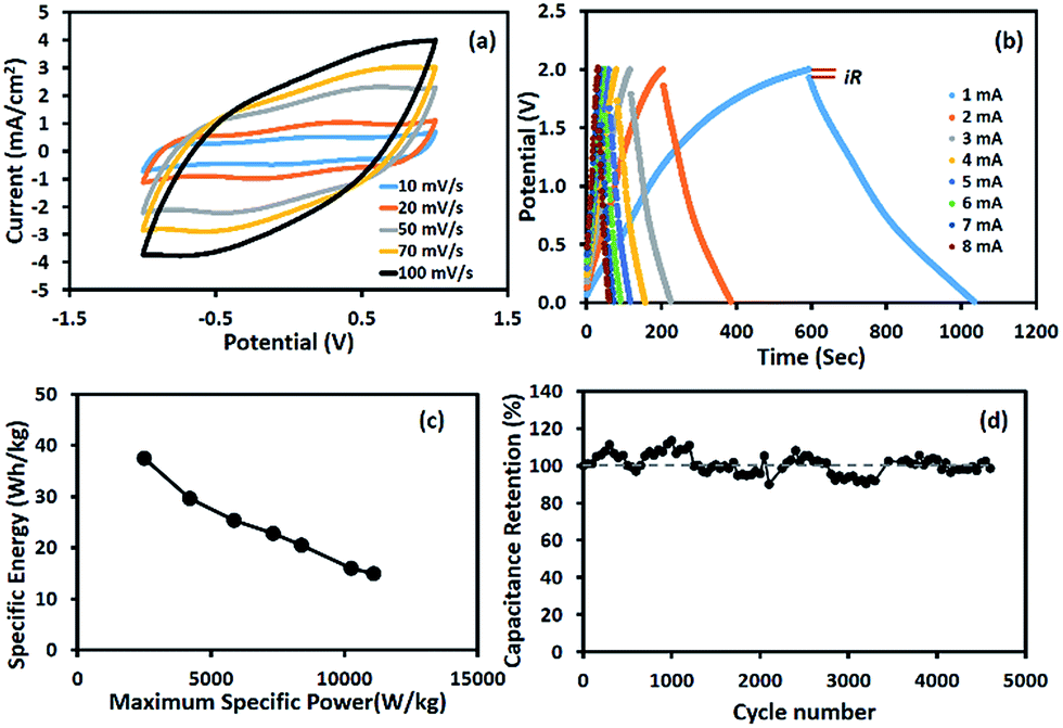
The charge storage performance of the symmetric supercapacitor based on the Mn3O4 nanofibres produced at 10 wt% Mn(OAc)2 is shown in Fig. 5. The cyclic voltammograms in Fig. 5a show pseudocapacitive behaviour with a broad peak due to surface redox reactions. The GCD curves in Fig. 5b show a wide working potential of 1.8 V excluding iR drop, which is twice that of the half-cell electrode. The calculated capacitances decrease with increasing scan rates and applied currents due to the limited diffusion of solvated ions.34 The calculated SC is 289 F g−1 at 1 mA for each cell or 1.25 mA cm−2. Table 1 compares the charge storage performances of Mn3O4-based supercapacitors. Most previous reports were based on a three-electrode system or half-cell.
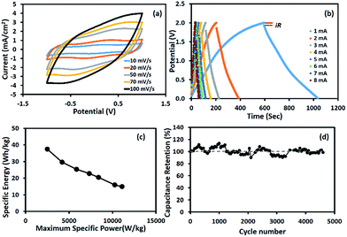 |
| | Fig. 5 (a) CV curves, (b) GCD curves, (c) Ragone plot, and (d) capacity retention of the symmetric supercapacitor based on Mn3O4 nanofibres electrospun at 10 wt% Mn(OAc)2 in 0.5 M Na2SO4. | |
Table 1 Charge storage performances of Mn3O4-based supercapacitor electrodes
| Materials |
Tested method |
Electrolyte |
Specific capacitance |
Ref. |
| Mn3O4 nanoparticles |
GCD at 0.1 A g−1 |
1 M Na2SO4 |
85 F g−1 (three electrodes) |
35 |
| Mn3O4 stacked sheet |
CV at 10 mV s−1 |
H2SO4–PVA (1:1 wt) gel electrolyte |
127 F g−1 (two electrodes) |
36 |
| Mn3O4 nanoparticles |
GCD at 0.5 mA cm−2 |
1 M Na2SO4 |
322 F g−1 (three electrodes) |
23 |
| Mn3O4 nanoparticles |
GCD at 0.5 mA cm−2 |
1 M Na2SO4 |
113 F g−1 (three electrodes) |
7 |
| As-spun Mn3O4 fibres |
GCD at 0.3 A g−1 |
1 M Na2SO4 |
155 F g−1 (three electrodes) |
28 |
| As-spun MnOx fibres |
CV at 10 mV s−1 |
1 M Na2SO4 |
161.22 F g−1 (two electrodes) |
37 |
| As-spun Mn3O4 fibres |
CV at 2 mV s−1 |
0.5 M Na2SO4 |
63.2 F g−1 (three electrodes) |
38 |
| As-spun Mn3O4 nanofibres |
GCD at 1 mA (1.25 mA cm−2) |
0.5 M Na2SO4 |
289 F g−1 (two electrodes) |
This work |
The Ragone plot of the device is shown in Fig. 5c. The specific energy and maximum specific power of the Mn3O4 symmetric supercapacitor are 37.4 W h kg−1 and 11.1 kW kg−1, respectively (see the calculation details in the ESI†). The stability of the symmetric supercapacitor based on the as-electrospun Mn3O4 nanofibres is shown in Fig. 5d, for which the capacity retention is over 98% after 4500 charge/discharge cycles.
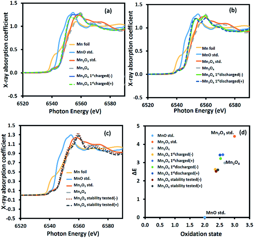
To further investigate the charge storage mechanism of Mn3O4, the average oxidation number of Mn at the positive and negative electrodes of the device after the 1st charge, the 1st discharge, and the long-term stability test of over 4500 cycles was determined by XAS. The normalized X-ray absorption near edge spectra (XANES) of the Mn-based materials are shown in Fig. 6a–c. The K-edge electron binding energies of Mn metal, MnO, Mn2O3, and Mn3O4 standards are 6539.00, 6544.17, 6548.61, and 6547.15 eV, respectively. After the 1st charge, the K-edge electron binding energies of Mn at the positive and negative electrodes were in between those of MnO (Mn2+) and Mn2O3 (Mn3+) at 6547.60 and 6546.80 eV, respectively. The average oxidation numbers of Mn at the positive and negative electrodes calculated using eqn (S8) in the ESI†39 are 2.61 and 2.38, respectively. Note that the average oxidation state of Mn in the as-calcined Mn3O4 is +2.67 (see Fig. 6d). The decreased oxidation number of Mn, especially at the negative electrode after the 1st charge, when compared with the bare electrode is due to solvated Na+ being inserted into the structure. The charge storage mechanism follows reactions (5) and (6):
| |
 | (5) |
| | |
NaδMnOx·nH2O ↔ MnOx·nH2O + δNa+ + δe−
| (6) |
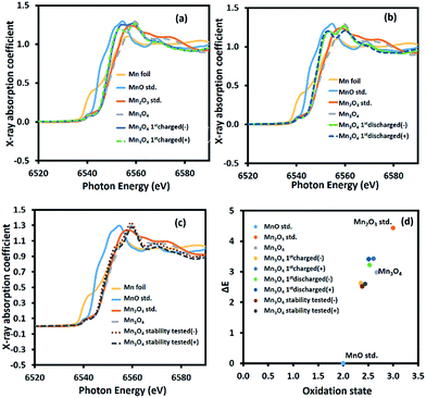 |
| | Fig. 6 Ex situ high-resolution XAS spectra after (a) the 1st charge, (b) the 1st discharge, and (c) the stability test, and (d) the average oxidation numbers of Mn in the manganese oxide electrodes compared with the Mn standard compounds. | |
This is because the adsorption of solvated cations can result in a lower binding energy.8,40 On the other hand, the partial oxidation of Mn2+ to Mn3+ at the positive electrode after the 1st charge leads to a slight change in the average oxidation number of Mn. Meanwhile, reduction of Mn3+ to Mn2+ occurs at the negative electrode, which significantly reduces the average oxidation number of Mn.
After the 1st discharge, the K-edge electron binding energies of Mn at the positive and negative electrode are 6547.58 and 6547.39 eV, respectively. The calculated Mn average oxidation numbers are +2.51 and +2.53 at the positive and negative electrodes, respectively. At the negative electrode, the solvated Na+ is desorbed from the electrode surface. At the same time, solvated SO42− is desorbed from the positive electrode. After the stability test, the average oxidation numbers of Mn at the positive and negative electrodes are +2.43 and +2.38, respectively, calculated from the K-edge electron binding energies of 6546.77 eV and 6546.69 eV, respectively. This decrease is due to the extraction of Mn2+ from the crystal structure. Note that all of the binding energies and oxidation states of Mn are listed in Table S1 of the ESI.†
The EQCM results of the as-electrospun Mn3O4 nanofibres in 0.5 M Na2SO4 at a scan rate of 10 mV s−1 are shown in Fig. 7. For the anodic potentials scanned from 0 to 0.5 V vs. Ag/AgCl, the mass change is reduced or under zero due to desorption of solvated Na+ cations. On the other hand, an augmented mass change is observed for the cathodic potential scanned from 0.5 to 0 V vs. Ag/AgCl due to the adsorption of solvated cations.41 However, the final mass change of the cathodic scan does not meet the initial mass change of the anodic scan. This confirms the XAS results, which showed that the average oxidation state of Mn changes over time or during cycling. In other words, the charge storage mechanism of the as-electrospun Mn3O4 nanofibres involves solvated cation adsorption/desorption with a mass change of ca. 80 ng cm−2. These EQCM results support the XAS results.
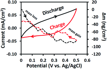 |
| | Fig. 7 CV curves and EQCM measurements of the as-electrospun Mn3O4 nanofibre electrode in 0.5 M Na2SO4. | |
Conclusions
Manganese oxide (Mn3O4) nanofibres were prepared by an electrospinning process of Mn(OAc2) in PAN with a subsequent calcination process at 500 °C for 2 h. The effect of the Mn(OAc2) loading content was investigated and it was found that the amount of Mn(OAc2) precursor affected the crystalline structure of the final Mn3O4 nanofibre products. The Mn3O4 nanofibres produced with different Mn(OAc2) contents were coated onto flexible CFP substrates using a spray coating technique and then electrochemically evaluated by CV, GCD, and EIS methods. The symmetric supercapacitor based on Mn3O4 nanofibres with diameters of 60–200 nm produced at 10 wt% Mn(OAc2) exhibits the highest SC, specific energy, and maximum specific power of 289 F g−1 at 1 mA, 37.4 W h kg−1 and 11.1 kW kg−1, respectively. The capacity retention is ca. 98% over 4500 cycles. Based on XAS, the charge storage mechanism of the as-calcined Mn3O4 nanofibres involves a phase transformation from Mn3O4 to NaδMnOx·nH2O during the first charge. After this, the mechanism is based on surface redox reactions due to adsorption/desorption of solvated ions. In addition, the EQCM measurements show that the solvated cation adsorption/desorption with a mass change of ca. 80 ng cm−2 on the Mn3O4 nanofibres plays a significant role in the charge storage mechanism of Mn3O4. The understanding of the charge storage mechanism of Mn2+(Mn3+)2O4 presented in this work could lead to further development of metal oxide-based pseudocapacitors.
Acknowledgements
This work was financially supported by the Thailand Research Fund and Vidyasirimedhi Institute of Science and Technology (RSA5880043). P. Suktha thanks the Centre of Excellence on Petrochemical and Materials Technology (PETROMAT), Department of Chemical Engineering, Faculty of Engineering, Kasetsart University, KURDI, the National Research University Project of Thailand (NRU) for financial support.
Notes and references
- B. Vidyadharan, R. A. Aziz, I. I. Misnon, G. M. Anil Kumar, J. Ismail, M. M. Yusoff and R. Jose, J. Power Sources, 2014, 270, 526–535 CrossRef CAS.
- P. Iamprasertkun, A. Krittayavathananon and M. Sawangphruk, Carbon, 2016, 102, 455–461 CrossRef CAS.
- M. Winter and R. J. Brodd, Chem. Rev., 2004, 104, 4245–4270 CrossRef CAS PubMed.
- J. Chmiola, G. Yushin, Y. Gogotsi, C. Portet, P. Simon and P. L. Taberna, Science, 2006, 313, 1760–1763 CrossRef CAS PubMed.
- P. Huang, C. Lethien, S. Pinaud, K. Brousse, R. Laloo, V. Turq, M. Respaud, A. Demortière, B. Daffos, P. L. Taberna, B. Chaudret, Y. Gogotsi and P. Simon, Science, 2016, 351, 691–695 CrossRef CAS PubMed.
- D. Pech, M. Brunet, H. Durou, P. Huang, V. Mochalin, Y. Gogotsi, P.-L. Taberna and P. Simon, Nat. Nanotechnol., 2010, 5, 651–654 CrossRef CAS PubMed.
- B. G. S. Raj, R. N. R. Ramprasad, A. M. Asiri, J. J. Wu and S. Anandan, Electrochim. Acta, 2015, 156, 127–137 CrossRef CAS.
- L. Yang, S. Cheng, X. Ji, Y. Jiang, J. Zhou and M. Liu, J. Mater. Chem. A, 2015, 3, 7338–7344 RSC.
- G. S. Gund, D. P. Dubal, B. H. Patil, S. S. Shinde and C. D. Lokhande, Electrochim. Acta, 2013, 92, 205–215 CrossRef CAS.
- C.-H. Yang, I. W. Sun, C.-T. Hsieh, T.-Y. Wu, C.-Y. Su, Y.-S. Li and J.-K. Chang, J. Mater. Chem. A, 2016, 4, 4015–4018 RSC.
- M.-J. Deng, P.-J. Ho, C.-Z. Song, S.-A. Chen, J.-F. Lee, J.-M. Chen and K.-T. Lu, Energy Environ. Sci., 2013, 6, 2178–2185 Search PubMed.
- M.-J. Deng, J.-K. Chang, C.-C. Wang, K.-W. Chen, C.-M. Lin, M.-T. Tang, J.-M. Chen and K.-T. Lu, Energy Environ. Sci., 2011, 4, 3942–3946 Search PubMed.
- M. Sawangphruk, P. Srimuk, P. Chiochan, A. Krittayavathananon, S. Luanwuthi and J. Limtrakul, Carbon, 2013, 60, 109–116 CrossRef CAS.
- D. Yang, J. Power Sources, 2011, 196, 8843–8849 CrossRef CAS.
- S. Chen, F. Liu, Q. Xiang, X. Feng and G. Qiu, Electrochim. Acta, 2013, 106, 360–371 CrossRef CAS.
- X. Hao, J. Zhao, Y. Li, Y. Zhao, D. Ma and L. Li, Colloids Surf., A, 2011, 374, 42–47 CrossRef CAS.
- N. Phattharasupakun, J. Wutthiprom, P. Chiochan, P. Suktha, M. Suksomboon, S. Kalasina and M. Sawangphruk, Chem. Commun., 2016, 52, 2585–2588 RSC.
- D. P. Dubal, D. S. Dhawale, R. R. Salunkhe, S. M. Pawar and C. D. Lokhande, Appl. Surf. Sci., 2010, 256, 4411–4416 CrossRef CAS.
- L. Laffont and P. Gibot, Mater. Charact., 2010, 61, 1268–1273 CrossRef CAS.
- L. Li, K. H. Seng, H. Liu, I. P. Nevirkovets and Z. Guo, Electrochim. Acta, 2013, 87, 801–808 CrossRef CAS.
- F. Gao, J. Qu, Z. Zhao, Q. Zhou, B. Li and J. Qiu, Carbon, 2014, 80, 640–650 CrossRef CAS.
- L. Wang, L. Chen, Y. Li, H. Ji and G. Yang, Powder Technol., 2013, 235, 76–81 CrossRef CAS.
- B. Gnana Sundara Raj, A. M. Asiri, J. J. Wu and S. Anandan, J. Alloys Compd., 2015, 636, 234–240 CrossRef CAS.
- N. A. Barakat, K.-D. Woo, S. Ansari, J.-A. Ko, M. A. Kanjwal and H. Y. Kim, Appl. Phys. A: Mater. Sci. Process., 2009, 95, 769–776 CrossRef CAS.
- E. Lee, T. Lee and B.-S. Kim, J. Power Sources, 2014, 255, 335–340 CrossRef CAS.
- Z. Li, X. Hu, D. Xiong, B. Li, H. Wang and Q. Li, Electrochim. Acta, 2016, 219, 339–349 CrossRef CAS.
- J. Zhao, C. Lai, Y. Dai and J. Xie, Mater. Lett., 2007, 61, 4639–4642 CrossRef CAS.
- J. Bhagwan, A. Sahoo, K. L. Yadav and Y. Sharma, Electrochim. Acta, 2015, 174, 992–1001 CrossRef CAS.
- S. Komaba, T. Tsuchikawa, A. Ogata, N. Yabuuchi, D. Nakagawa and M. Tomita, Electrochim. Acta, 2012, 59, 455–463 CrossRef CAS.
- T.-H. Wu, D. Hesp, V. Dhanak, C. Collins, F. Braga, L. J. Hardwick and C.-C. Hu, J. Mater. Chem. A, 2015, 3, 12786–12795 RSC.
- P. Iamprasertkun, A. Krittayavathananon, A. Seubsai, N. Chanlek, P. Kidkhunthod, W. Sangthong, S. Maensiri, R. Yimnirun, S. Nilmoung, P. Pannopard, S. Ittisanronnachai, K. Kongpatpanich, J. Limtrakul and M. Sawangphruk, Sci. Rep., 2016, 6, 37560 CrossRef CAS PubMed.
- K. Terayama and M. Ikeda, Trans. Jpn. Inst. Met., 1983, 24, 754–758 CrossRef CAS.
- A. González, E. Goikolea, J. A. Barrena and R. Mysyk, Renewable Sustainable Energy Rev., 2016, 58, 1189–1206 CrossRef.
- P. Suktha, P. Chiochan, P. Iamprasertkun, J. Wutthiprom, N. Phattharasupakun, M. Suksomboon, T. Kaewsongpol, P. Sirisinudomkit, T. Pettong and M. Sawangphruk, Electrochim. Acta, 2015, 176, 504–513 CrossRef CAS.
- Y. Fan, X. Zhang, Y. Liu, Q. Cai and J. Zhang, Mater. Lett., 2013, 95, 153–156 CrossRef CAS.
- D. P. Dubal and R. Holze, Energy, 2013, 51, 407–412 CrossRef CAS.
- K. Mondal, C.-Y. Tsai, S. Stout and S. Talapatra, Mater. Lett., 2015, 148, 142–146 CrossRef CAS.
- X. Zhao, Y. Du, Y. Li and Q. Zhang, Ceram. Int., 2015, 41, 7402–7410 CrossRef CAS.
- S. Daengsakul, P. Kidkhunthod, O. Soisang, T. Kuenoon, A. Bootchanont and S. Maensiri, Microelectron. Eng., 2015, 146, 38–42 CrossRef CAS.
- K. P. Lucht and J. L. Mendoza-Cortes, J. Phys. Chem. C, 2015, 119, 22838–22846 CrossRef CAS.
- W.-Y. Tsai, P.-L. Taberna and P. Simon, J. Am. Chem. Soc., 2014, 136, 8722–8728 CrossRef CAS PubMed.
Footnote |
| † Electronic supplementary information (ESI) available. See DOI: 10.1039/c6ra28499j |
|
| This journal is © The Royal Society of Chemistry 2017 |
Click here to see how this site uses Cookies. View our privacy policy here. 
 Open Access Article
 This Open Access Article is licensed under a Creative Commons Attribution-Non Commercial 3.0 Unported Licence
 *a
*a