 Open Access Article
Creative Commons Attribution 3.0 Unported Licence
Restricting the liquid–liquid phase separation of PTB7-Th:PF12TBT:PC71BM by enhanced PTB7-Th solution aggregation to optimize the interpenetrating network†
Bin Tangab,
Jiangang Liu*a,
Xinxiu Caoa,
Qiaoqiao Zhaoa,
Xinhong Yua,
Shijun Zhengb and
Yanchun Han *a
*a
aState Key Laboratory of Polymer Physics and Chemistry, Changchun Institute of Applied Chemistry, Chinese Academy of Sciences, 5625 Renmin Street, Changchun 130022, P. R. China. E-mail: ychan@ciac.ac.cn; niitawh@ciac.ac.cn
bSchool of Materials Science and Engineering, Zhengzhou University, Zhengzhou 450001, P. R. China
First published on 23rd March 2017
Abstract
The current understanding of the active layer morphology in ternary organic solar cells (OSCs) is superficial owing to more variables and complexity compared to that of binary OSCs. The PTB7-Th:PF12TBT:PC71BM ternary system with complementary polymer absorption spectra and efficient energy transfer from PF12TBT to PTB7-Th was anticipated to have an outstanding performance. However, only a limited improvement in the power conversion efficiency (PCE) was achieved when the ternary devices were processed from CB/DIO. This is because large PC71BM domains formed with the addition of amorphous PF12TBT and the PF12TBT molecules embedded in the large PC71BM domains served as trap sites. Constraining the formation of large PC71BM domains and avoiding PF12TBT molecules being fully embedded in PC71BM domains are needed for a better performance. Polymer pre-aggregation before liquid–liquid phase separation is beneficial to construct bicontinuous interpenetrating networks with proper phase-separated domains. Therefore, para-xylene was introduced into CB/DIO to cause a weak polymer–solvent interaction for enhanced PTB7-Th solution-phase aggregation. The enhanced PTB7-Th aggregation in the CB/PX/DIO solution restricted the extent of the liquid–liquid phase separation, and a well-developed polymer network formed with improved PTB7-Th crystallinity, which prevented large PC71BM domains from forming via fluid-phase Ostwald ripening in the liquid–solid phase separation stage. The appearance of PF12TBT emission and increased PTB7-Th emission in the ternary film processed from CB/PX/DIO suggested that fewer PF12TBT molecules were embedded in the PC71BM domains, and the energy transfer from PF12TBT to PTB7-Th was more efficient. Thus, PCE increased from 8.09% for binary blends processed from CB/DIO to 9.28% for ternary blends processed from CB/PX/DIO.
Introduction
Organic solar cells (OSCs) have garnered significant research interest because of their prominent merits such as low-cost, mechanical flexibility, and solution processing in the past few decades.1–4 Although impressive progress has been achieved,5 further development is required to ensure a bright industrial future for OSCs. Heeger pointed out that to reach the 20% goal of OSCs, a broad absorption spectrum comparable to that of Si is essential.6 However, outstanding donor materials, which break through the 10% efficiencies, generally belong to low bandgap polymers with a narrow absorption spectrum converging in the 600–800 nm region.7,8Ternary solar cells have been shown to be an excellent strategy for single-junction OSCs to overcome the relatively narrow spectral overlap of organic polymer absorption bands with the solar spectrum, resulting in exceptional power conversion efficiencies (PCE) over 12%.9 As a promising approach, ternary solar cells have attracted significant attention, and a tremendous amount of work has established the basic function principles of ternary OSCs, which generally include charge transfer, energy transfer, and parallel-linkage or alloy structures.10–12 To ensure the third component functions effectively, the proper location of the third component is essential. In the case of a charge transfer mechanism, selectively locating the third component at the interface is needed to facilitate exciton dissociation and guarantee effective charge transport. As to the energy transfer mechanism, the energy donor and energy acceptor should be close enough for the non-radiative dipole–dipole interaction.13
However, there have been limited ternary systems reported that surpass their corresponding binary OSCs in PCE.14,15 Reasonable explanations are that the optimized binary blend morphology was greatly influenced by the addition of a third component, and the inappropriate location of the third component with dissimilar chemical and physical natures may function as a recombination center.16 To ensure a good performance, the formation of bicontinuous interpenetrating networks by phase-separated domains (10–20 nm) is necessary both in the binary and ternary blends.17 Nonetheless, when a third component was introduced into the optimized binary systems, it may ruin the interpenetrating network,18,19 cause large phase separation,15 and bring in recombination centers with inappropriate third component locations16,20 or incompatible third components.14 The third component is generally limited to a low loading ratio in charge transfer mechanism systems and energy transfer mechanism systems due to the morphology factor,21–23 which may set an upper limit for the improvement.
Several works have attempted to study the ternary blends morphology. Li et al. established the phase diagram of P3HT/PCPDTBT/PCBM ternary blends,18 finding that the addition of more than 20 wt% PCPDTBT resulted in completely amorphous blends with poor PCE. Further work by Machui et al. suggested that the addition of PCPDTBT would deteriorate the PCBM crystalline phase, resulting in decreased electron mobility.19 Ohkita et al. proposed that the surface energy and crystallization of the matrix materials play important roles in determining the third component distribution,24 and the interfacial location content of the third component can be improved by promoting the matrix material crystallinity. These works demonstrated the importance of morphology control in ternary blends. However, considering that the morphology control in binary blends is already highly complicated, ternary blends introduce more variables that further promote the difficulty of morphology control. Thus, substantial efforts are essential to enhance our understanding of the ternary blends morphology and unravel the fundamental operating principles of how to manipulate the ternary blend morphology towards the ideal morphology.
In the following work, a ternary system guided by the energy transfer mechanism was designed. We chose a binary system based on poly[4,8-bis(5-(2-ethylhexyl)thiophen-2-yl)benzo[1,2b:4,5b′]dithiophene-co-3-fluorothieno[3,4-b]thiophene-2-carboxylate] (PTB7-Th) and [6,6]-phenyl C71 butyric acid methyl ester (PC71BM) because of its high efficiency. The wide bandgap polymer poly[9,9-didodecylfluorene-alt-(bis-thienylene) benzothiadiazole] (PF12TBT) was introduced as the third component. We first studied the morphology evolution from binary blends to ternary blends, and the film showed a rougher texture and larger domain size with increased amorphous PF12TBT content. We suggested that the introduction of amorphous PF12TBT molecules deteriorated the PTB7-Th network and led to increased phase separation as it has been reported that a preformed polymer network by polymer aggregation is essential to prevent large fullerene-rich domains from forming in the liquid–solid phase separation process.25,26 The wetting coefficient (ω) was calculated to analyze the location of PF12TBT, and it suggested that the PF12TBT molecules tend to be embedded in the PC71BM domains. A chlorobenzene (CB)/para-xylene (PX)/1, 8-diiodooctane (DIO) solvent system instead of CB/DIO was employed to refine the PTB7-Th network by promoting the PTB7-Th solution-phase aggregation. The AFM and PL results showed that the ternary films presented decreased the phase separation and fewer PF12TBT molecules were embedded in the PC71BM domains when processed from CB/PX/DIO. The ternary device achieved a PCE of 9.28% with an optimized morphology. Yu et al. developed a ternary system (PTB7-Th:PID2:PC71BM) with a PCE of 9.2% by the synergistic effects of energy transfer and hole relay processes,27 and our results implied that there is still room for the improvement in the photovoltaic performance by carefully manipulating the ternary blend morphology.
Experimental
Materials
PTB7-Th (Mw = 120 kDa, PDI < 3.0) and PF12TBT (Mw = 10.3 kDa, PDI = 1.8) were purchased from 1-Material Inc. PC71BM was purchased from American Dye Source. Solvent CB, PX and DIO were purchased from Sigma-Aldrich. All the materials and solvents were used as received.Device fabrication
The solar cells were fabricated on ITO-coated glass substrates. The ITO-coated glass substrates were first cleaned by ultrasonic bath in deionized water, acetone and isopropyl alcohol for 15 min, respectively. Then, the cleaned ITO substrates were dried by nitrogen flow. A UV ozone treatment for 25 min was applied before poly(ethylenedioxythiophene):poly(styrenesulfonate) (PEDOT:PSS, Baytron P4083) was spin coated onto the ITO substrates. The PEDOT:PSS was spin coated onto ITO substrates at 5000 rpm for 60 s and then annealed at 140 °C for 30 min. The PTB7-Th:PF12TBT solution with different weight ratios was first prepared by dissolving the polymer blends in CB/DIO (97/3, v/v) or CB/PX/DIO (87/10/3, v/v/v) solvents, and the solution was kept still overnight and subsequently mixed with PC71BM with a polymer![[thin space (1/6-em)]](https://www.rsc.org/images/entities/char_2009.gif) :
:![[thin space (1/6-em)]](https://www.rsc.org/images/entities/char_2009.gif) PC71BM weight ratio of 1
PC71BM weight ratio of 1![[thin space (1/6-em)]](https://www.rsc.org/images/entities/char_2009.gif) :
:![[thin space (1/6-em)]](https://www.rsc.org/images/entities/char_2009.gif) 1.5. Then, the binary or ternary solutions were spin-cast on top of the PEDOT:PSS layer in a nitrogen glove box. The active layers were spin-rinsed with methanol at 3000 rpm for 30 s. A ZnO solution was prepared as reported28 and spin-cast onto the active layers. The Al cathode (100 nm) was deposited on top of the active layer by thermal evaporation under a vacuum of 4 × 10⁻⁴ Pa. The photoactive area of the cells is 0.072 cm2, which is defined by the vertical overlap of the ITO anode and Al cathode.
1.5. Then, the binary or ternary solutions were spin-cast on top of the PEDOT:PSS layer in a nitrogen glove box. The active layers were spin-rinsed with methanol at 3000 rpm for 30 s. A ZnO solution was prepared as reported28 and spin-cast onto the active layers. The Al cathode (100 nm) was deposited on top of the active layer by thermal evaporation under a vacuum of 4 × 10⁻⁴ Pa. The photoactive area of the cells is 0.072 cm2, which is defined by the vertical overlap of the ITO anode and Al cathode.
Characterization
The ultraviolet-visible (UV-vis) absorption spectra were acquired with a Lambda 750 spectrometer (PerkinElmer, Wellesley, MA).Photoluminescence spectra were measured with a LabRam HR800 spectrometer (Horiba Jobin Yvon). All the films were excited by a 532 nm solid-state laser.
The atomic force microscopy (AFM) and transmission electron microscopy (TEM) were applied to characterize the morphology of the binary and ternary blend films. The AFM measurements were conducted on a SPA-300HV instrument with a SPI3800N controller (Seiko Instruments Inc., Japan). The tapping mode was adopted to avoid damaging the film. TEM experiments were performed by a JEOL JEM-1011 transmission electron microscope under an accelerating voltage of 100 kV.
The out-of-plane grazing incidence X-ray diffraction (GIXD) was employed to analyze the crystallographic information. The GIXD measurements were conducted by a Bruker D8 Discover reflector with Cu Kα radiation (λ = 1.54 Å). Data were acquired just above the critical angle (α ≈ 0.18°) of the films with an X-ray generation power of 40 kV tube voltage and 40 mA tube current. The scan speed is 5 s per step with a 0.05° increment (2θ).
The contact angles were measured on a KRüSS DSA10-MK2 (KRüSS GmbH, Germany) drop shape analysis (DSA) system at an ambient temperature.
The current density–voltage (J–V) curves were measured using a Keithley 2400 source meter in the glove box. A Newport solar simulator with an AM 1.5 global filter operated at 100 mW cm−2 was used to simulate the AM 1.5G solar irradiation. External quantum efficiency (EQE) measurements were performed with a lock-in amplifier at a chopping frequency of 280 Hz during illumination with the monochromatic light from a xenon lamp.
Results and discussion
Förster resonance energy transfer (FRET) from PF12TBT to PTB7-Th
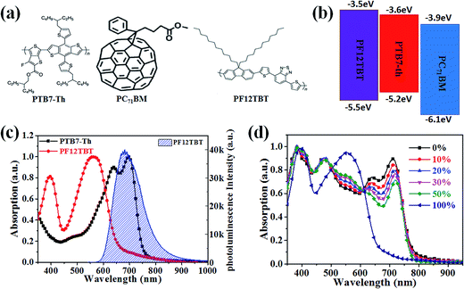
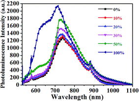
The molecular structures and optical properties of the materials used in this study are shown in Fig. 1. PF12TBT exhibits a wider bandgap (∼2.0 eV) compared to PTB7-Th (∼1.6 eV), thus PF12TBT shows an absorption spectrum mainly in the visible region, while PTB7-Th possesses an absorption spectrum cut-off in the near infrared region.29 The absorption spectrum of the PF12TBT film has typical absorption characteristics for donor–acceptor type conjugated polymers with two distinct absorption bands centered at ≈400 nm (belong to the π–π* or n–π* transition) and at ≈550 nm (which can be ascribed to the intramolecular charge transfer (ICT) band of the D/A copolymer). The absorbance spectrum of PTB7-Th shows a fine vibrionic structure with two peaks at 640 nm and 710 nm whose energies correspond to the transitions between the ground state and the first two vibrionic levels of the excited state.30 The fine vibrionic structure is ascribed to the semi-crystalline property of PTB7-Th, and the relative intensities of the two peaks have been used to evaluate the degree of structure order. As shown in Fig. 1c, the photoluminescence (PL) spectra of the PF12TBT presents one dominant peak at 680 nm, which overlapped well with the absorption spectrum of PTB7-Th. It is noteworthy that the two polymers possess complementary absorption spectra in the vis-NIR region, and the emission spectrum of PF12TBT overlaps with the absorption spectrum of PTB7-Th largely, which indicates that efficient Förster resonance energy transfer (FRET) may occur from PF12TBT to PTB7-Th. The UV-vis absorption spectra of the ternary films with different PF12TBT contents were measured to study the changes in absorption. Fig. 1d shows that with an increased PF12TBT loading ratio, the ternary films showed gradually enhanced absorption strength from 380 nm to 420 nm and from 500 nm to 605 nm while simultaneously showing a decreased absorption capability from 605 nm to 730 nm. This is consistent with the absorption spectra of PF12TBT and PTB7-Th, as shown in Fig. 1c.In order to verify the efficient energy transfer from PF12TBT to PTB7-Th, the steady-state PL spectra of PTB7-Th:PF12TBT blend films with different PF12TBT doping ratios were measured under the excitation of 532 nm light and are shown in Fig. 2. It is apparent that the neat PF12TBT film showed a strong emission peak at 680 nm, while the neat PTB7-Th film showed a relatively weak emission peak at 755 nm. It is noteworthy that the emission intensity of PF12TBT markedly quenched in the blend film, while the emission peak at 755 nm which belongs to PTB7-Th is highly enhanced along with the increase of PF12TBT content, the phenomenon suggested that there definitely exists an energy transfer from PF12TBT to PTB7-Th. The PTB7-Th:PF12TBT blend films showed smooth surfaces, and no obvious phase separation was observed, as shown in Fig. S1,† which suggested the good compatibility between PTB7-Th and PF12TBT. The above results suggested it is suitable to design the PTB7-Th:PF12TBT:PC71BM ternary OSCs based on the complementary absorption spectrum and efficient energy transfer from PF12TBT to PTB7-Th.
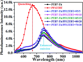 | ||
| Fig. 2 Steady state PL spectra showed quenching and sensitized emission of the PTB7-Th:PF12TBT films when excited at 532 nm. | ||
Restricting the extent of liquid–liquid phase separation of PTB7-Th:PF12TBT:PC71BM by enhanced PTB7-Th solution aggregation to optimize the interpenetrating network
The performance of PTB7-Th:PC71BM devices is largely determined by the nanoscopic and mesoscopic active layer morphology according to extensive studies.31–34 When PF12TBT was introduced, more variables were brought in. Thus, the ternary solar cells need to be carefully investigated to achieve a successful case.The location of PF12TBT in ternary blends would determine whether it functions as a sensitizer or as a trap site, several previous studies have shown that surface energy serves an important role in the segregation tendency of each material when employed in blends.22,24 By calculating the wetting coefficient (ω) of PF12TBT in the binary blends on the basis of the interfacial surface energy, the location of PF12TBT in the ternary blends can be predicted. Contact angle measurements with ultrapure water and ethylene glycol on the thin film of individual materials were used to estimate the surface energy. The surface energies of pristine PTB7-Th, PF12TBT and PC71BM were determined to be 23.5 mN m−1, 33.1 mN m−1 and 29.7 mN m−1, respectively. The wetting coefficient of PF12TBT (ωPF12TBT) in blends of PTB7-Th and PC71BM can be calculated by Young's equation as the following:35
| ωC = (γC–B − γC–A)/γA–B | (1) |
| γX–Y = γX + γY − 2(γXγY)0.5exp[−β(γX − γY)2] | (2) |
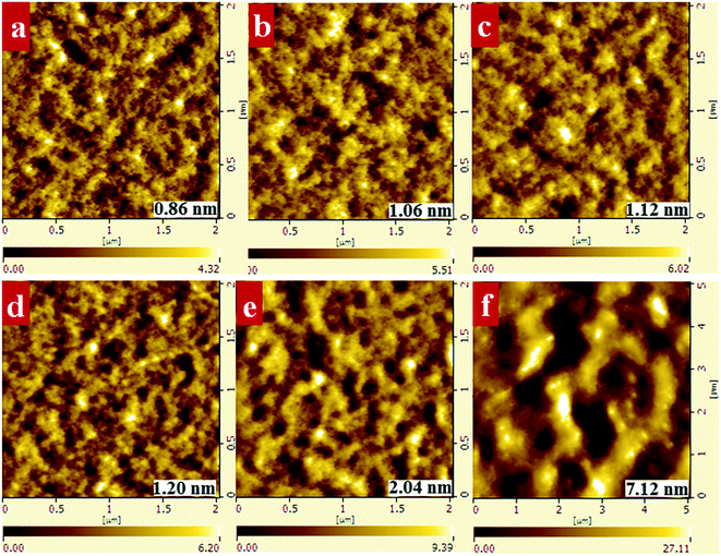
Atomic force microscopy (AFM) and transmission electron microscopy (TEM) were applied to explore the morphology evolution when PF12TBT was incorporated. For comparison, all the films were processed from a CB/DIO (97/3, v/v) solvent because it is the optimized condition for the PTB7-Th:PC71BM blends as previously reported.31,33 For all the samples in this study, the overall polymer to PC71BM ratio was kept at 1![[thin space (1/6-em)]](https://www.rsc.org/images/entities/char_2009.gif) :
:![[thin space (1/6-em)]](https://www.rsc.org/images/entities/char_2009.gif) 1.5, and different ratios of PF12TBT to PTB7-Th were examined to reveal the influence of PF12TBT on the ternary blend morphology. The AFM height images are shown in Fig. 3. The film of the binary control, PTB7-Th:PC71BM, exhibited a rather smooth surface and fine phase separation. The film turns rougher as implied by the increased grain size and root mean square value (RMS) with increasing PF12TBT contents. When the loading ratio of PF12TBT achieved 50%, the film showed a very rough texture and large domain size. Moreover, it is noteworthy that the PF12TBT:PC71BM blend film shows micrometer-sized phase separation. The TEM images corresponded well with the AFM results, as shown in Fig. S2,† and the PTB7-Th:PC71BM sample showed a featureless TEM image, which is in agreement with the work by McNeill et al.31 With increasing PF12TBT content, a larger phase separation was observed; the PF12TBT:PC71BM TEM image film showed large phase separation with poor contrast, which may suggest the domains were impure (Fig. 4).
1.5, and different ratios of PF12TBT to PTB7-Th were examined to reveal the influence of PF12TBT on the ternary blend morphology. The AFM height images are shown in Fig. 3. The film of the binary control, PTB7-Th:PC71BM, exhibited a rather smooth surface and fine phase separation. The film turns rougher as implied by the increased grain size and root mean square value (RMS) with increasing PF12TBT contents. When the loading ratio of PF12TBT achieved 50%, the film showed a very rough texture and large domain size. Moreover, it is noteworthy that the PF12TBT:PC71BM blend film shows micrometer-sized phase separation. The TEM images corresponded well with the AFM results, as shown in Fig. S2,† and the PTB7-Th:PC71BM sample showed a featureless TEM image, which is in agreement with the work by McNeill et al.31 With increasing PF12TBT content, a larger phase separation was observed; the PF12TBT:PC71BM TEM image film showed large phase separation with poor contrast, which may suggest the domains were impure (Fig. 4).
The photoluminescence quenching of donor and acceptor materials reflects the ability of excitons of donors or acceptors to reach the donor/acceptor interface, which is related to the phase separation.37 Thus, the steady PL spectrum is employed to deduce information on the phase separation. The PTB7-Th:PC71BM film showed a weak emission peak at 745 nm, which resulted from the overlap of PTB7-Th and PC71BM emission. Both PTB7-Th and PC71BM showed emission peaks nearby (755 nm for PTB7-Th and 720 nm for PC71BM, as shown in Fig. 2 and S4†). It is noteworthy that the emission of the PF12TBT:PC71BM film was dominated by the PC71BM emission, and the PF12TBT emission was highly quenched, which implied that large PC71BM domains were formed. The PL result in combination with the TEM image of the PF12TBT:PC71BM film, which showed large phase separation with poor contrast, may further confirm the conclusion that PF12TBT tend to be embedded in large PC71BM domains, leading to the highly quenched PF12TBT emission. With the increased PF12TBT loading ratio, the PL intensity of the PTB7-Th:PF12TBT:PC71BM films gradually ascended. The rise of PL intensity can be explained by the increased phase separation or enhanced PTB7-Th emission with the energy transfer from PF12TBT to PTB7-Th. However, the slightly blue shifted emission peaks may indicate that the elevated PL intensity was dominated by the increased phase separation.
For the solution processed polymer:fullerene blends, it is generally believed that to prevent large phase separation from occurring, a preformed polymer network, which means enough solution-phase polymer aggregation occurs before liquid–liquid phase separation, is essential.25,26 It has also been proposed that in the PTB7:PC71BM system, the PC71BM selectively dissolved in DIO and then intercalated into the PTB7 network in the liquid–solid phase separation process, thereby ensuring small PC71BM domains.38 We proposed that the polymer networks became incomplete with the addition of PF12TBT, as evidenced by the decreased PTB7-Th crystallinity in the ternary blends shown in Fig. S3.† Because the nonvolatile DIO selectively dissolves PC71BM, which allowed a long duration liquid–solid phase separation process, larger PC71BM domains formed via fluid-phase Ostwald ripening with less PTB7-Th network limitation.
Yang et al. have proposed that structural compatibility between two polymers, which includes the preferred molecular orientation, crystallite size and domain structure, would play an important role in achieving high performance ternary OSCs.14 Given the amorphous property of PF12TBT, the preferred molecular orientation may not be the limiting factor. The PTB7-Th/PF12TBT blend morphology was also investigated, as shown in Fig. S1,† and all the films showed smooth surfaces without obvious changes. No large phase separation was observed even with a high PF12TBT content (50%). These results imply the good structural compatibility between PTB7-Th and PF12TBT, and the ternary blend morphology evolution may not be largely affected by the structural compatibility.
As mentioned above, the deteriorated PTB7-Th networks are responsible for the increased phase separation of the ternary films. McGehee et al. have proposed that the solution-phase polymer aggregates coalesce and form a preformed network before liquid–liquid phase separation, and this network sets the characteristic length scale for the liquid–solid phase separation process.26 Thus, we attempted to refine the PTB7-Th networks in ternary films by promoting the solution-phase PTB7-Th aggregation. The fundamental role solvent plays in dictating polymer conformation has been known since the early work of Flory,39 and the Flory–Huggins interaction parameter (χ12) has been widely applied to analyze the polymer aggregation behavior.40–42 A larger χ12 for PTB7-Th and the corresponding solvent, which represents a weaker polymer–solvent interaction, is needed to promote the PTB7-Th aggregation. We showed that the CB/PX/DIO (87/10/3, v/v/v) solvent system with finely tuned χ12 by the introduction of PX successfully promoted the PTB7-Th aggregation. The χ12 for PTB7-Th and different solvents are listed in Table 1. Here, we ignored the existence of DIO when evaluating the χ12, because the PTB7-Th molecule is generally believed to be insoluble in DIO. The χ12 is estimated from Hansen solubility parameters (HSPs) according to the expression:43
| χ12 = V(Δδd2 + 0.25Δδp2 + 0.25ΔδH2)/RT | (3) |
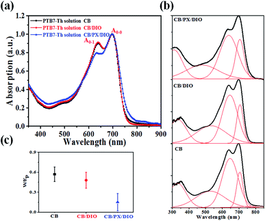
The absorption spectra of PTB7-Th in different solvent systems, as shown in Fig. 5a, were used to evaluate the solution-phase PTB7-Th aggregation. The A0–0 and A0–1 denote different transitions between the ground state and the first two vibrionic levels of the excited state, and the intensity ratio of A0–0/A0–1 can be used to evaluate the degree of PTB7-Th aggregation according to eqn (4):44,45
 | (4) |
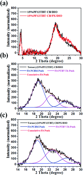
We then studied the crystallinity of ternary films processed from CB/DIO and CB/PX/DIO. Fig. 6 showed the out of plane GIXD profile for the ternary blends with a 15% loading ratio of PF12TBT, and the curves were fitted with Gaussian peaks to give a quantitative analysis of PTB7-Th crystallinity. The peak at 2θ = 22.5° corresponds to the π–π stacking peak of PTB7-Th with a d-spacing of 3.93 Å,46 while the two peaks at 2θ = 19.0° and 2θ = 26.2° were ascribed to PC71BM.47,48 For the PTB7-Th dominantly adopted face-on orientation, we employed the PTB7-Th (010) peak area to evaluate the crystallinity of PTB7-Th in the blend films. The PTB7-Th (010) peak was integrated, and the peak area showed a 41% improvement for film processed from CB/PX/DIO compared to that of film processed from CB/DIO. These results suggested that the CB/PX/DIO solvent system improved PTB7-Th aggregation in the solution phase and finally resulted in enhanced PTB7-Th crystallinity in films. An interesting phenomenon is that the PTB7-Th:PF12TBT film showed a decreased d-spacing of PTB7-Th, as shown in Fig. S6,† while the d-spacing of PTB7-Th in the PTB7-Th:PF12TBT:PC71BM film recovered. This may be accounted for by the fact that the PF12TBT molecules tend to be embedded in the PC71BM domains, thus, the interaction between PTB7-Th and PF12TBT was suppressed.
The photoluminescence spectra of the binary and ternary films were also carefully investigated and are shown in Fig. 7. The PTB7-Th:PC71BM film processed from CB/DIO showed a weak emission peak at 745 nm. The binary film processed from CB/PX/DIO showed almost the same PL spectra as that processed from CB/DIO. We presumed that whether the binary film processed from CB/DIO or from CB/PX/DIO, enough PTB7-Th aggregates would ensure a well-developed PTB7-Th network, resulting in proper phase-separated domains. The ternary film spin-cast from CB/DIO showed enhanced PC71BM emission, which reflected that more excitons were quenched in the larger PC71BM domain size beyond the exciton diffusion length. When it came to the ternary film spin-cast from CB/PX/DIO, improvements in two regions were observed. In the 600–660 nm region, the increase was ascribed to the PF12TBT emission, while the enhancement of the peak at 745 nm was because of enhanced PTB7-Th emission. The absence of PF12TBT emission in the ternary film processed from CB/DIO is easy to understand when we consider the fact that PF12TBT molecules are largely embedded in PC71BM domains by the driving force of the surface energy. Then, the presence of PF12TBT emission in the ternary film processed from CB/PX/DIO may indicate that fewer PF12TBT molecules were embedded in the PC71BM domains. We suggest that with the limitation of the refined PTB7-Th network, the PC71BM formed smaller domains, which may not trap the PF12TBT molecules as effectively as the larger domains. The increase in the PTB7-Th emission further confirmed our conclusion, as förster resonance energy transfer is a non-radiative energy transfer process that acts through long-range dipole–dipole interactions between two molecules,13 and the energy transfer from PF12TBT to PTB7-Th works more efficiently with fewer PF12TBT molecules embedded in large PC71BM domains.
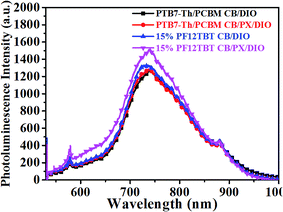 | ||
| Fig. 7 Steady state PL spectra of binary and ternary films spin-cast from CB/DIO and from CB/PX/DIO. | ||
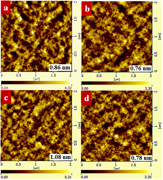
We investigated the morphology of binary and ternary films to verify that the improved PTB7-Th crystallinity can prevent large PC71BM domains from forming. As shown in Fig. 8, the PTB7-Th:PC71BM film processed from CB/DIO showed a smooth surface with a RMS value of 0.86 nm while the PTB7-Th:PF12TBT:PC71BM film presented a relatively rough surface with an RMS value of 1.08 nm. When processed from CB/PX/DIO, both the binary and ternary films showed decreased RMS values, which are 0.76 nm and 0.78 nm, respectively. The ternary films with a 15% loading ratio of PF12TBT processed from CB/PX/DIO showed decreased grain size compared to that processed from CB/DIO. The AFM results may partially show that the lateral phase separation was decreased by enhancing the PTB7-Th solution-phase aggregation. We suggest that further analysis by the grazing incidence resonant soft X-ray scattering (GI-RSoXS) may give more detailed information as reported.49
Photovoltaic performance
The binary and ternary photovoltaic devices were fabricated to study the influence of active layer morphology on the device performance. The device performances measured under simulated AM 1.5 illumination at 100 mW cm−2 are summarized in Table 2, and the corresponding current density versus voltage (J–V) curves are shown in Fig. 9a. The ternary devices with 15% PF12TBT processed from CB/DIO showed a slightly increased PCE of 8.56% compared to 8.09% for the control binary devices. The improvement arose from a significantly enhanced Jsc (from 16.22 mA cm−2 to 18.22 mA cm−2) as predicted by the optical enhancement with the addition of PF12TBT. The drop in FF (from 64% to 61%) may be attributed to the deterioration of the interpenetrating network and improper location of PF12TBT. The larger PC71BM domains formed in the ternary active layers processed from CB/DIO, which drastically decreased the FF; the scarce PF12TBT molecules hardly established their own percolation channel for charge transfer as a third component, thus the PF12TBT molecules in the PC71BM domains would result in charge recombination, which further drops the FF. The ternary devices processed from CB/PX/DIO showed an extra improvement in device performance compared to that processed from CB/DIO, with Voc = 0.78 V, Jsc = 18.89 mA cm−2, FF = 63% and PCE = 9.28%. The improvement was attributed to the decreased PC71BM domains by the limitation of the refined PTB7-Th network and optimized distribution of the PF12TBT molecules. The binary devices processed from CB/PX/DIO gave a PCE of 8.12%, which is almost unchanged, suggesting a limited morphology difference between the binary active layers processed from CB/DIO and processed from CB/PX/DIO. The EQE was studied to further improve our understanding of the relationship between device performance and active layer morphology and is shown in Fig. 9b. The Jsc values calculated from the integration of EQE spectra were listed in Table 2, which agreed well with the Jsc value obtained from the J–V curve within 5% error. Because both PF12TBT and PC71BM show strong absorption in the 400–600 nm region, we suggest the enhancement was the combined result of energy transfer and morphology factors. The large PC71BM domains and PF12TBT molecules serving as trap sites would constrain the improvement of EQE as in the ternary devices processed from CB/DIO. The EQE further improved with the optimized active layer morphology when the active layers were processed from CB/PX/DIO.| Voc (V) | Jsc (mA cm−2) | Calculated Jsc (mA cm−2) | FF | PCE (%) best (average) | |
|---|---|---|---|---|---|
| PTB7-Th/PC71BM CB/DIO | 0.78 | 16.22 | 16.04 | 0.64 | 8.09 (8.02) |
| PTB7-Th/PC71BM CB/PX/DIO | 0.78 | 16.01 | 15.90 | 0.65 | 8.12 (7.98) |
| 15% PF12TBT CB/DIO | 0.77 | 18.22 | 18.10 | 0.61 | 8.56 (8.38) |
| 15% PF12TBT CB/PX/DIO | 0.78 | 18.89 | 18.83 | 0.63 | 9.28 (9.13) |
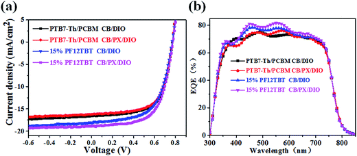 | ||
| Fig. 9 Current density versus voltage curves of binary and ternary devices (a). EQE curves for the binary and ternary devices (b). | ||
The carrier mobility is sensitive to the morphology. Bicontinuous interpenetrating networks by proper phase-separated domains are required to achieve balance, and high carrier mobility enables the charges to reach the electrodes prior to recombination.6,50 Space charge limited current (SCLC) measurements for characterizing the charge carrier transport along the vertical direction were performed (Fig. S7†), and the calculated results are listed in Table 3. It is noteworthy that the ternary device processed from CB/DIO possessed the lowest hole mobility and the most unbalanced hole and electron mobility (μe/μh = 14.3), thus the accumulation of holes in the D–A interfaces would finally result in charge recombination. This may explain the lowest FF of ternary devices processed from CB/DIO, as shown in Table 2. The ternary device processed from CB/PX/DIO showed increased hole mobility and more balanced hole and electron mobility, which corresponds to the increased FF. Due to the hole transport by the p-type polymer of PTB7-Th, the hole mobility is closely related to the PTB7-Th phase. As a consequence, the ternary device processed from CB/DIO with a deteriorated PTB7-Th network showed poor hole mobility, and the ternary device processed from CB/PX/DIO showed hole mobility comparable to that of binary devices, suggesting the hole transport channel was optimized with the enhanced PTB7-Th crystallinity.
| μh (cm2 V−1 s−1) | μe (cm2 V−1 s−1) | μe/μh | |
|---|---|---|---|
| PTB7-Th/PC71BM CB/DIO | 1.04 × 10⁻⁴ | 5.39 × 10⁻⁴ | 5.2 |
| PTB7-Th/PC71BM CB/PX/DIO | 2.02 × 10⁻⁴ | 6.97 × 10⁻⁴ | 3.5 |
| 15% PF12TBT CB/DIO | 3.22 × 10⁻⁵ | 4.59 × 10⁻⁴ | 14.3 |
| 15% PF12TBT CB/PX/DIO | 1.41 × 10⁻⁴ | 7.41 × 10⁻⁴ | 5.3 |
Conclusions
To enhance our understanding of the ternary blend morphology, the energy transfer ternary system (PTB7-Th:PF12TBT:PC71BM) was designed, and the ternary blend morphology was systematically investigated. Our work showed that the PTB7-Th network deteriorated with the introduction of PF12TBT, and larger PC71BM domains formed with fewer limitations. Furthermore, PF12TBT molecules tend to be embedded in the PC71BM domains by the driving force of the surface energy, which would result in charge recombination. These unfavorable morphology factors restrict the improvement of the ternary system. The CB/PX/DIO solvent system was employed to obtain a refined PTB7-Th network by promoting the PTB7-Th aggregation in solution. The AFM images and PL spectrum demonstrated that smaller PC71BM domains and optimized PF12TBT distribution were achieved when the ternary blend films processed from CB/PX/DIO. The ternary devices with detrimental morphology showed limited improvement (PCE from 8.09% to 8.56%) when processed from CB/DIO. Further improvement (PCE = 9.28%) was achieved with optimized morphology when the ternary devices were processed from CB/PX/DIO. Our work reveals the significance of ternary blend morphology for device performance, and highlights the potential for further boosting the performance of ternary OSCs by morphology control.Acknowledgements
This work was supported by the National Natural Science Foundation of China (21334006, 51573185), National Basic Research Program of China (973 Program-2014CB643505), the Strategic Priority Research Program of the Chinese Academy of Science (Grant No. XDB12020300).References
- P. L. T. Boudreault, A. Najari and M. Leclerc, Chem. Mater., 2011, 23, 456–469 CrossRef CAS.
- A. Facchetti, Chem. Mater., 2010, 23, 733–758 CrossRef.
- M. A. Green, K. Emery, Y. Hishikawa and W. Warta, Progress in Photovoltaics: Research and Applications, 2010, 18, 144–150 CrossRef CAS.
- R. F. Service, Science, 2011, 332, 293 CrossRef CAS PubMed.
- S. Li, L. Ye, W. Zhao, S. Zhang, S. Mukherjee, H. Ade and J. Hou, Adv. Mater., 2016, 28, 9423–9429 CrossRef CAS PubMed.
- A. J. Heeger, Adv. Mater., 2014, 26, 10–28 CrossRef CAS PubMed.
- Y. Liu, J. Zhao, Z. Li, C. Mu, W. Ma, H. Hu, K. Jiang, H. Lin, H. Ade and H. Yan, Nat. Commun., 2014, 5, 5293 CrossRef CAS PubMed.
- S.-H. Liao, H.-J. Jhuo, Y.-S. Cheng and S.-A. Chen, Adv. Mater., 2013, 25, 4766–4771 CrossRef CAS PubMed.
- W. Zhao, S. Li, S. Zhang, X. Liu and J. Hou, Adv. Mater., 2017, 29, 1604059 CrossRef PubMed.
- L. Lu, M. A. Kelly, W. You and L. Yu, Nat. Photonics, 2015, 9, 491–500 CrossRef CAS.
- T. Ameri, P. Khoram, J. Min and C. J. Brabec, Adv. Mater., 2013, 25, 4245–4266 CrossRef CAS PubMed.
- Q. An, F. Zhang, J. Zhang, W. Tang, Z. Deng and B. Hu, Energy Environ. Sci., 2016, 9, 281–322 Search PubMed.
- J. R. Lakowicz, Principles of Fluorescence Spectroscopy, Springer, New York, 2006 Search PubMed.
- Y. Yang, W. Chen, L. Dou, W.-H. Chang, H.-S. Duan, B. Bob, G. Li and Y. Yang, Nat. Photonics, 2015, 9, 190–198 CrossRef CAS.
- H. Cha, D. S. Chung, S. Y. Bae, M.-J. Lee, T. K. An, J. Hwang, K. H. Kim, Y.-H. Kim, D. H. Choi and C. E. Park, Adv. Funct. Mater., 2013, 23, 1556–1565 CrossRef CAS.
- S. Honda, T. Nogami, H. Ohkita, H. Benten and S. Ito, ACS Appl. Mater. Interfaces, 2009, 1, 804–810 CAS.
- G. Yu, J. Gao, J. C. Hummelen, F. Wudl and A. J. Heeger, Science, 1995, 270, 1789–1791 CAS.
- N. Li, F. Machui, D. Waller, M. Koppe and C. J. Brabec, Sol. Energy Mater. Sol. Cells, 2011, 95, 3465–3471 CrossRef CAS.
- F. Machui, S. Rathgeber, N. Li, T. Ameri and C. J. Brabec, J. Mater. Chem., 2012, 22, 15570–15577 RSC.
- B. H. Lessard, J. D. Dang, T. M. Grant, D. Gao, D. S. Seferos and T. P. Bender, ACS Appl. Mater. Interfaces, 2014, 6, 15040–15051 CAS.
- T. Goh, J. S. Huang, B. Bartolome, M. Y. Sfeir, M. Vaisman, M. L. Lee and A. D. Taylor, J. Mater. Chem. A, 2015, 3, 18611–18621 CAS.
- J.-S. Huang, T. Goh, X. Li, M. Y. Sfeir, E. A. Bielinski, S. Tomasulo, M. L. Lee, N. Hazari and A. D. Taylor, Nat. Photonics, 2013, 7, 479–485 CrossRef CAS.
- Q. An, F. Zhang, L. Li, J. Wang, Q. Sun, J. Zhang, W. Tang and Z. Deng, ACS Appl. Mater. Interfaces, 2015, 7(6), 3691–3698 CAS.
- S. Honda, H. Ohkita, H. Benten and S. Ito, Adv. Energy Mater., 2011, 1, 588–598 CrossRef CAS.
- J. J. van Franeker, M. Turbiez, W. Li, M. M. Wienk and R. A. Janssen, Nat. Commun., 2015, 6, 6229 CrossRef CAS PubMed.
- J. A. Bartelt, J. D. Douglas, W. R. Mateker, A. E. Labban, C. J. Tassone, M. F. Toney, J. M. J. Fréchet, P. M. Beaujuge and M. D. McGehee, Adv. Energy Mater., 2014, 4, 1079–1098 Search PubMed.
- L. Lu, W. Chen, T. Xu and L. Yu, Nat. Commun., 2015, 6, 7327 CrossRef CAS PubMed.
- J. Wang, X. Zhang, Q. Yang, C. Yan, Y. Fu, B. Zhang and Z. Xie, RSC Adv., 2016, 6, 25744–25750 RSC.
- B. Minnaert and M. Burgelman, Prog. Photovoltaics, 2007, 15, 741–748 CAS.
- F. Bencheikh, D. Duché, C. M. Ruiz, J. J. Simon and L. Escoubas, J. Phys. Chem. C, 2015, 119(43), 24643–24648 CAS.
- W. Huang, E. Gann, L. Thomsen, C. Dong, Y.-B. Cheng and C. R. McNeill, Adv. Energy Mater., 2015, 5, 1401259 CrossRef.
- J. Huang, J. H. Carpenter, C. Z. Li, J. S. Yu, H. Ade and K. Y. Jen, Adv. Mater., 2016, 28, 967–974 CrossRef CAS PubMed.
- L. Zhao, S. Zhao, Z. Xu, Q. Yang, D. Huang and X. Xu, Nanoscale, 2015, 7, 5537–5544 RSC.
- J. Kong, I.-W. Hwang and K. Lee, Adv. Mater., 2014, 26, 6275–6283 CrossRef CAS PubMed.
- M. Sumita, K. Sakata, S. Asai, K. Miyasaka and H. Nakagawa, Polym. Bull., 1991, 25, 265–271 CrossRef CAS.
- D. Li and A. W. Neumann, J. Colloid Interface Sci., 1990, 137, 304–307 CrossRef CAS.
- M. A. Ruderer, S. Guo, R. Meier, H.-Y. Chiang, V. Körstgens, J. Wiedersich, J. Perlich, S. V. Roth and P. Müller-Buschbaum, Adv. Funct. Mater., 2011, 21, 3382–3391 CrossRef CAS.
- S. J. Lou, J. M. Szarko, T. Xu, L. Yu, T. J. Marks and L. X. Chen, J. Am. Chem. Soc., 2011, 133, 20661–20663 CrossRef CAS PubMed.
- P. J. Flory, Principles of Polymer Chemistry, Cornell University Press, 1953 Search PubMed.
- N. Cho, H.-L. Yip and A. K.-Y. Jen, Appl. Phys. Lett., 2013, 102, 233903 CrossRef.
- E. Pavlopoulou, S. K. Chang, S. S. Lee, Z. Chen, A. Facchetti, M. F. Toney and Y. L. Loo, Chem. Mater., 2014, 26, 5020–5027 CrossRef CAS.
- K. Zhou, J. Liu, M. Li, X. Yu, R. Xing and Y. Han, J. Polym. Sci., Part B: Polym. Phys., 2014, 53, 288–296 CrossRef.
- C. M. Hansen, Hansen Solubility Parameters: A User's Handbook, CRC Press, Hoboken, 2007 Search PubMed.
- F. C. Spano, J. Chem. Phys., 2005, 122, 234701 CrossRef PubMed.
- C. J. Schaffer, J. Schlipf, E. Dwi Indari, B. Su, S. Bernstorff and P. Müller-Buschbaum, ACS Appl. Mater. Interfaces, 2015, 7, 21347–21355 CAS.
- T. Liu, L. Huo, X. Sun, B. Fan, Y. Cai, T. Kim, J. Y. Kim, H. Choi and Y. Sun, Adv. Energy Mater., 2016, 6, 1502109 CrossRef.
- S. Liu, P. You, J. Li, J. Li, C.-S. Lee, B. S. Ong, C. Surya and F. Yan, Energy Environ. Sci., 2015, 8, 1463–1470 CAS.
- S. Rathgeber, J. Perlich, F. Kühnlenz, S. Türk, D. A. M. Egbe, H. Hoppe and R. Gehrke, Polymer, 2011, 52, 3819–3826 CrossRef CAS.
- C. J. Schaffer, C. Wang, A. Hexemer and P. Müller-Buschbaum, Polymer, 2016, 105, 357–367 CrossRef CAS.
- X. Guo, M. Zhang, J. Tan, S. Zhang, L. Huo, W. Hu, Y. Li and J. Hou, Adv. Mater., 2012, 24, 6536–6541 CrossRef CAS PubMed.
Footnote |
| † Electronic supplementary information (ESI) available. See DOI: 10.1039/c6ra28306c |
| This journal is © The Royal Society of Chemistry 2017 |

