
 Open Access Article
 This Open Access Article is licensed under a Creative Commons Attribution-Non Commercial 3.0 Unported Licence
Enhanced thermoelectric performance in n-type polycrystalline SnSe by PbBr2 doping
Debo Liab,
Xiaojian Tanb,
Jingtao Xu *b,
Guoqiang Liub,
Min Jinb,
Hezhu Shaob,
HuaJie Huanga,
Jianfeng Zhang*a and
Jun Jiang*b
*b,
Guoqiang Liub,
Min Jinb,
Hezhu Shaob,
HuaJie Huanga,
Jianfeng Zhang*a and
Jun Jiang*b
aCollege of Mechanics and Materials, Hohai University, Nanjing 211100, China. E-mail: jfzhang_sic@163.com
bNingbo Institute of Materials Technology and Engineering, Chinese Academy of Sciences, Ningbo 315201, China. E-mail: xujingtao@nimte.ac.cn; jjun@nimte.ac.cn
First published on 23rd March 2017
Abstract
A series of PbBr2-doped polycrystalline SnSe samples were synthesized by melting and hot pressing. By PbBr2 doping, the carrier concentration of SnSe was increased to 1.86 × 1019 cm−3 from 2.41 × 1017 cm−3, resulting in an increased electrical conductivity of 40 ± 2 S cm−1 at 713 K while the undoped SnSe was only 5.1 ± 0.3 S cm−1. Meanwhile, the PbBr2-doped samples also exhibit a larger density of state effective mass (0.812m0). Therefore, a high power factor of 4.8 ± 0.5 μW cm−1 K−2 and a peak ZT of 0.54 ± 0.1 were achieved at 793 K perpendicular to the hot pressing direction.
I. Introduction
With the progress of society, energy and environmental problems become the most urgent challenges facing mankind in the 21st century. Thermoelectric devices, which enable direct conversion between thermal and electrical energy, have become some of the most promising candidates to meet this challenge.1–3 The conversion efficiency of a thermoelectric device is determined by the figure of merit ZT of the thermoelectric material. ZT = S2σT/κ, where S, σ, κ, and T are the Seebeck coefficient, electrical conductivity, total thermal conductivity (a sum of electronic thermal conductivity κe and lattice thermal conductivity κl), and the absolute temperature in Kelvin, respectively.4 To obtain a high ZT, one should enhance the power factor, reduce the thermal conductivity or both simultaneously.Rock-salt structure IV–VI compounds, such as PbTe, PbSe, and SnTe, are the best thermoelectric materials in the middle to high temperature range (600–920 K).5–9 Recently, another IV–VI compound SnSe was reported to exhibit a surprising ZT = 2.6.10 The high ZT benefits from the ultralow thermal conductivity (0.23 W m−1 K−1 at 973 K). SnSe adopts a layered structure crystallized in the orthorhombic Pnma space group at room temperature, leading to strong anisotropic properties. The highest ZT of p-type SnSe single crystal is as high as 2.3–2.6 in the bc plane and as relatively low as 0.8 along the a axis.10
The thermoelectric application of SnSe single crystal is seriously limited by the poor mechanical properties and strict growth conditions. Polycrystalline materials are regarded to overcome these difficulties and have been drawing more and more attentions. However, the studies on SnSe polycrystalline were mainly focused on the p-type samples, and the ZTs are much lower than the single crystal.11–15 In practical applications, p-type and n-type materials are combined to fabricate the p-leg and n-leg of thermoelectric modules, respectively. Thus it is essential to develop the thermoelectric properties of n-type SnSe as well as p-type one.
SnSe is an intrinsic p-type material, and it has been reported that Se loss can induce p–n carrier transition.16 Halogen doping are found to be an effective way for preparation of n-type SnSe.17–20 In this work, we chose PbBr2 as the n-type dopant to optimize the carrier concentration and enhance the ZT values of polycrystalline SnSe. Br is an effective dopant to convert SnSe from p-type to n-type semiconductor and Pb can decrease the thermal conductivity for Pb have a heavier relative atomic mass. The anisotropic thermoelectric transport properties of our hot-pressed SnSe polycrystalline are also discussed. Moreover, by comparing with the other halogen doped SnSe, we demonstrate that the increased density of state effective mass also play an important role in the ZT optimization besides carrier concentration turning in our PbBr2 doped SnSe samples.
II. Experimental
The basic materials (Sn granule, 99.999%; Se granule, 99.999%; and PbBr2 powder, 99.99%) were weighed according to the stoichiometric compositions of SnSe0.95–x mole% PbBr2 (x = 0, 1, 2, 3, and 4) and sealed in high vacuum (10−2 Pa) in quartz tubes. The sealed quartz tubes were put into a rocking furnace and heated to 1193 K to melt the materials for 1 h. Then the tubes were taken out of the furnace and air-cooled to room temperature. The obtained ingots were ground into powders in an agate mortar and sieved between 200–300 mesh. The powders were then densified by hot pressing at 753 K for 30 min under a pressure of 60 MPa in vacuum to get Ø 12.7 mm × 10 mm pellet.The phase composition was analyzed by the X-ray diffraction (XRD, Bruker D8) with Cu Kα radiation at room temperature. The fractured and polished surfaces of the samples were observed by the scanning electron microscopy (SEM, Quanta FEG 250). The chemical compositions and the distributions of elements were determined using an energy dispersive X-ray spectrometer (EDXS). The Hall coefficient RH was measured at room temperature using a physical properties measurement system (Quantum Design PPMS-9) in magnetic fields ranging from −5–5 T. The carrier concentration n and mobility μ were calculated via n = 1/(eRH) and μ = σRH, respectively.
The columns were cut into 10 mm × 2 mm × 2 mm bars for electrical property measurement and a disk-shape sample of Ø 8 mm × 2 mm for thermal transport property measurement. The S and the σ were simultaneously measured (ULVAC-RIKO ZEM-3) under a helium atmosphere from 300–793 K. The uncertainty of the Seebeck coefficient and electrical conductivity measurements was 5%. The total thermal conductivity was calculated from κtot = DρCp, where D, ρ, and Cp are the thermal diffusivity, the density, and the heat capacity, respectively. The D was measured by the laser flash diffusivity method (Netzsch, LFA-457), ρ was measured using the Archimedes principle and Cp was taken from previous reports.10 The uncertainty of the thermal conductivity was estimated to be within 8%. The relative density of all the samples is not less than 97% of the theoretical value (6.18 g cm−3). Considering the uncertainties for σ, S and κ, the combined uncertainty for all measurements involved in the calculation of ZT is about 20%.
III. Results and discussions
Strong anisotropic structure is clearly observed in the XRD patterns performed on the samples cut perpendicular and parallel to the pressure directions (Fig. 1a) because of the layered crystal structure of SnSe. The ratio of the integral intensity of plane (400) to plane (111) is 7.96 for perpendicular to the pressing direction and 0.16 parallel to the pressing direction, respectively. Fig. 1b shows the room temperature XRD patterns for both undoped and doped SnSe polycrystalline samples measured perpendicular to the pressing direction. As seen, the diffraction patterns could be indexed to the orthorhombic phase with a Pnma symmetry of SnSe (JCPDS # 48-1224) without any impurity phase. | ||
| Fig. 1 (a) XRD patterns of the SnSe0.95–2% PbBr2 parallel and perpendicular to pressure; (b) XRD patterns of the SnSe0.95–x% PbBr2 (x = 0, 1, 2, 3, and 4) perpendicular to pressure. | ||
The degree of orientation of the bc-planes is evaluated by the orientation factor F(400), which can be calculated by the Lotgering method according to:21,22
 | (1) |
 | (2) |
 | (3) |
| PbBr2 content (%) | RH (cm3 C−1) | n (cm−3) | σ (S cm−1) | μ (cm2 V−1 s−1) | F(400) |
|---|---|---|---|---|---|
| x = 0 | 25.93 | 2.41 × 10¹⁷ | 0.46 | 11.93 | 0.43 |
| x = 1 | 0.40 | 1.56 × 10¹⁹ | 13.33 | 5.34 | 0.53 |
| x = 2 | 0.34 | 1.84 × 10¹⁹ | 14.88 | 5.05 | 0.41 |
| x = 3 | 0.34 | 1.86 × 10¹⁹ | 8.80 | 2.96 | 0.50 |
| x = 4 | 0.41 | 1.53 × 10¹⁹ | 9.71 | 3.97 | 0.42 |
We take SnSe0.95–3% PbBr2 as an example to study the microstructure of our samples. As shown in Fig. 2a, the polycrystalline sample (SnSe0.95–3% PbBr2 as a representative) exhibits a lamellar microstructure, which is consistent with the layered crystal structure. The lamellar grains with size of 50 μm align along the same direction generally in the fractured surface. Fig. 2b shows the polished surface of the same sample. No second phase is observed. The mapping results shown in Fig. 2c–f indicate that the elements of Sn, Se, Br and Pb are all uniformly distributed, suggesting a homogenous doping of PbBr2.
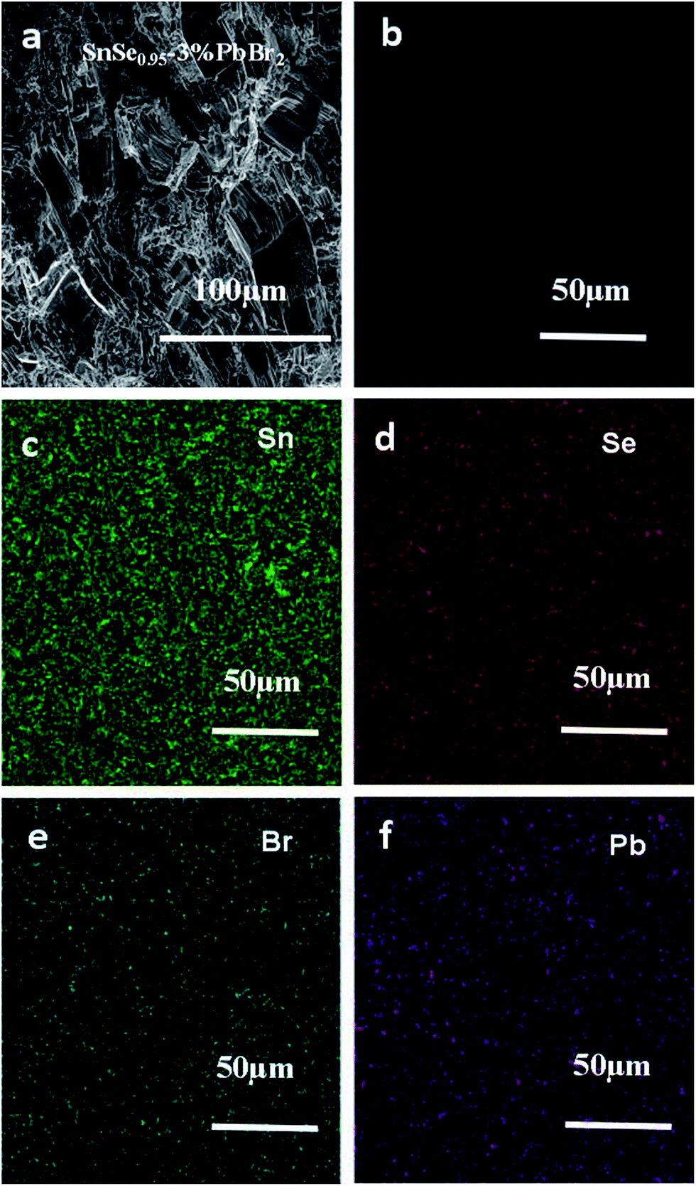 | ||
| Fig. 2 (a) and (b) are the fractured and polished surface morphologies of SnSe0.95–3% PbBr2 sample, respectively; (c)–(f) are the EDS mapping for Se, Br and Pb in this sample, respectively. | ||
The single crystal of SnSe show strong anisotropic properties due to the layered-like crystal structure. High thermoelectric performance was found along the bc plane, while lower thermal conductivity was reported along the a-axis. The polycrystalline SnSe samples have also been reported to show anisotropic properties.10,17,18 But better thermoelectric performance are found in different directions in several reports.11,17,18 Here, we investigate the anisotropic properties of our PbBr2-doped polycrystalline SnSe samples. The thermoelectric transport properties SnSe0.95–2% PbBr2 are measured parallel (∥) and perpendicular (⊥) to the hot pressing direction, and the results are shown in Fig. 3. In Fig. 3a, the electrical conductivity in both directions decreases with increasing temperature to 430 K, and then increases with temperature to 700 K. σ⊥ is much higher than σ∥ in the whole temperature range. The absolute values of the Seebeck coefficient increase with temperature for both directions. The values in the two directions are very close to each other. Therefore, the power factors perpendicular to the hot pressing direction are much larger than the other direction. The highest power factor is 4.33 μW cm−1 K−2 at 740 K. The thermal conductivity decreases with increasing temperature below 773 K (Fig. 3c). κ⊥ is higher than κ∥ in the whole temperature range, similar to the electrical conductivity. After calculation, higher ZT values are obtained in the direction perpendicular to the pressure, but the anisotropy is much smaller in the ZT values.
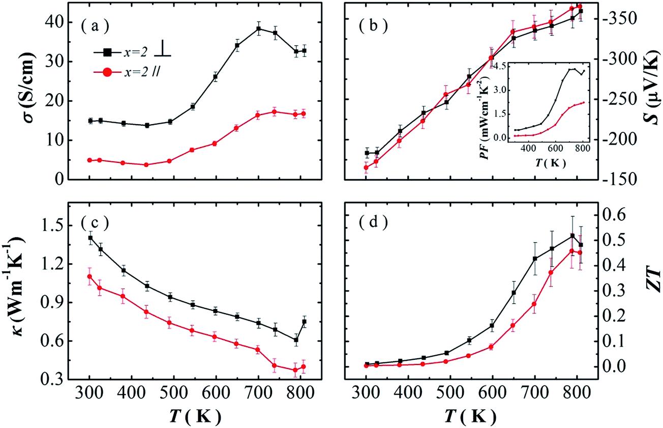 | ||
| Fig. 3 (a) The electrical conductivity, (b) Seebeck coefficient, (c) thermal conductivity, and (d) ZT as a function of temperature for SnSe0.95–2% PbBr2 measured parallel and perpendicular to the pressing direction. The power factor is shown in the inset of (b). | ||
Better thermoelectric performance in the direction perpendicular to the pressure is consistent with our previous reports, and other layered-like structure thermoelectric materials, such as Bi2Te3, In4Se3−δ.23–25 But several groups also reported that higher ZT values in the direction parallel to the pressure.10,12,14,15,26
In polycrystalline SnSe samples, the Seebeck coefficients are always reported to be similar in different directions. Therefore, the anisotropy ZT values originate from the ratio of the electrical conductivity to the thermal conductivity. Here, we summarize the ratio of electrical conductivity and the thermal conductivity in two directions from different literatures (Table 2). It can be seen that at 750 K the ratio of σ⊥/σ∥ to κ⊥/κ∥ decides higher ZT values in the two direction. We also find that for the reports with higher ZTs in the direction parallel to the pressure, there are two reports which shows larger σ⊥/σ∥ at room temperature. It seems that the anisotropic degree in electrical conductivity is much more important to determine the overall anisotropic thermoelectric performance.
| σ⊥/σ∥ | κ⊥/κ∥ | Optimal direction | |||
|---|---|---|---|---|---|
| 300 K | 750 K | 300 K | 750 K | ||
| I-doping Zhang et al.18 | 1.33 | 0.86 | 1.60 | 1.44 | ∥ |
| Na-doping Chere et al.13 | 1.80 | 1.48 | 1.46 | 1.23 | ∥ |
| Ag-doping Chen et al.16 | 1.24 | 0.73 | 1.55 | 1.58 | ∥ |
| SPS SnSe Li et al.26 | 2.51 | 1.25 | 1.33 | 1.45 | ∥ |
| S-doping Han et al.14 | 2.35 | 1.09 | 1.49 | 1.42 | ∥ |
| Br&Pb-doping Chang et al.19 | 1.96 | 1.41 | 1.40 | 1.40 | ∥ |
| BiCl3-doping Wang et al.17 | 2.90 | 2.15 | 1.44 | 1.68 | ⊥ |
| Na-doping Leng, et al.15 | 1.92 | 2.00 | 1.42 | 1.38 | ⊥ |
| Ag-doping Leng, et al.28 | 1.82 | 1.48 | 1.33 | 1.22 | ⊥ |
| PbBr2-doping this work | 3.13 | 2.19 | 1.27 | 1.68 | ⊥ |
We now move to the discussion of enhanced electronic transport properties by PbBr2 doping. Fig. 4 summarized the Seebeck coefficient (black dots) at room temperature of SnSe0.95–x% PbBr2 (x = 0, 1, 2, 3, and 4) samples as a function of carrier concentration. For comparison, the results of I-doped (blue dots) and BiCl3-doped SnSe (red dots) are also shown.17,18 It is found that the Seebeck coefficients of these samples are similar while the corresponding carrier concentration are very different from one another. To shed light on the undiscovered origin of such difference, we use the single parabolic band model27 to fit the experimental measurements and plot them in Fig. 4. The Seebeck coefficient and carrier concentration are fitted according to the following equations. (Eqn (4)–(6)) (the scattering factor here is −1/2):
 | (4) |
 | (5) |
 | (6) |
 | ||
| Fig. 4 Seebeck coefficient as a function of Hall carrier concentration at room temperature for Halogen doped SnSe samples. | ||
Fig. 5 shows the thermoelectric properties measured perpendicular the hot pressing direction for the SnSe0.95–x% PbBr2 (x = 0, 1, 2, 3, and 4) samples: (a) electrical conductivity, (b) Seebeck coefficient, (c) power factor, and (d) thermal conductivity. As Fig. 5a shown, the electrical conductivities could be divided into three stages as reported:10 first, a metallic transport behavior from 300–500 K; then showing a typical semiconductor behavior up to 750 K; and finally dropping above 750 K. In the temperature range of 300–600 K, the electrical conductivities of x = 1 and 2 is higher than those of x = 3 and 4. This may be attributed to the decrease of mobility caused by enhanced carrier scattering in the samples with larger x. Between 600–800 K, the electrical conductivity shows a significant increase with increasing PbBr2 content and reaches a maximum of 40.2 S cm−1 at 713 K for the sample with 3% PbBr2. We summarized the room temperature carrier concentration, mobility and electrical conductivity of the PbBr2-doped SnSe samples in Table 1. As may be seen, the carrier concentration is significantly increased from 1017 to 1019 cm−3 by PbBr2 doping, which indicates PbBr2 is an effective n-type dopant of SnSe. As the PbBr2 content increasing from x = 1 to 3, the carrier concentration increases and mobility decreases, lead to a highest electrical conductivity of 14.9 S cm−1 in SnSe0.95–2% PbBr2. The decrease in carrier concentration from x = 3 to x = 4 may be caused by the volatilization of PbBr2 (Table 1).
 | ||
| Fig. 5 (a) The electrical conductivity, (b) Seebeck coefficient, (c) power factor, and (d) total thermal conductivity and lattice thermal conductivity for SnSe0.95–x% PbBr2 (x = 0, 1, 2, 3, and 4) as a function of temperature. | ||
As Fig. 5b shown, the SnSe0.95 samples shows the n–p type transition, which is consistent with the results by Chen et al.16 For the doped systems, the Seebeck coefficients are less dependent on the amount of PbBr2. In the whole measured temperature range, all the PbBr2-doped samples exhibit negative Seebeck coefficients and increased with the increasing temperature. For example, the Seebeck coefficient significantly enhances from −197 μV K−1 at 300 K to −363 μV K−1 at 793 K for SnSe0.95–3% PbBr2.
As may be seen in Fig. 5c, PbBr2-doped SnSe samples exhibit much higher power factors than pristine SnSe0.95 due to the significantly increased electrical conductivity. In the whole measured temperature range, the power factor of doped SnSe roughly increases with temperature. The observed highest power factor is 4.8 μW cm−1 K−2 in SnSe0.95–3% PbBr2 at 793 K.
The total thermal conductivity as well as lattice thermal conductivity are shown in Fig. 5d as a function of temperature. The lattice thermal conductivities are calculated by subtracting the electronic contribution from the total thermal conductivities. The electronic contribution is computed using the Wiedemann–Franz law: κe = LσT where L is the Lorenz number. The Lorenz number L is given as:
 | (7) |
Fig. 6 displays the ZT values as a function of temperature for SnSe0.95–x% PbBr2 (x = 0, 1, 2, 3, and 4). With increasing temperature, the ZT values are roughly increased until 793 K. For the pristine SnSe0.95, the maximum ZT value is ∼0.14 at 793 K. By PbBr2 doping, the ZTs are significantly increased and reach a highest value of 0.54 in SnSe0.95–3% PbBr2 at 793 K, due to the significantly enhanced electrical transport properties and the reduced thermal conductivity. It should be emphasized that a ZT of 0.54 in PbBr2-doped SnSe samples synthesized by hot pressing is a very conservative value. As the corresponding thermal conductivity (>0.6 W m−1 K−1 at 793 K) is much higher than the single crystal, there is still room to further increase the ZT of PbBr2-doped SnSe. By nanocomposites or alloys, the thermal conductivity can be decreased and the thermoelectric performance can be further improved. Recently, a report by Chang et al. shows that Pb/Br doped SnSe show a higher ZT of ∼1.2 where the thermal conductivity is reduced to 0.3 W m−1 K−1.19
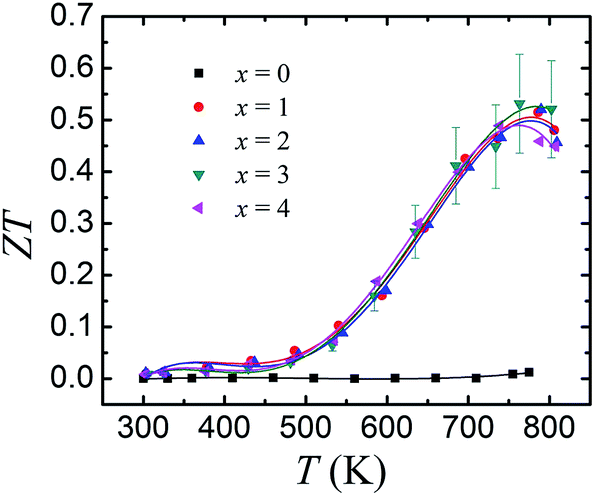 | ||
| Fig. 6 Temperature dependence of ZT values for SnSe0.95–x% PbBr2 (x = 0, 1, 2, 3, and 4). | ||
IV. Summary
The n-type SnSe0.95–PbBr2 samples with orientation were synthesized by hot pressing. PbBr2 is proved an effective dopant to significantly increase the carrier concentration, and the samples show negative Seebeck coefficients in the whole temperature range. Our polycrystalline SnSe0.95–PbBr2 samples show higher thermoelectric performance in the direction perpendicular to the pressure. As a result of detailed analysis, the DOS effective mass of PbBr2-doped sample is larger than the previously reported n-type SnSe, leading to an enhanced Seebeck coefficient with electrical conductivity less affected. These effects results in a high power factor of 4.8 μW cm−1 K−2 and a ZT of 0.54 at 793 K in the SnSe0.95–3% PbBr2 systems.Acknowledgements
This work was supported by the National Nature Science Foundation of China (No. 11304327, 11404348, 11404350, 11234012), Ningbo Municipal Natural Science Foundation (No. 2014A610011), Ningbo Science and Technology Innovation Team (No. 2014B82004), Zhejiang Provincial Science Fund for Distinguished Young Scholars (LR16E020001) and Natural Science Foundation of Jiangsu Province (BK20161506).References
- L. Bell, Science, 2008, 321, 1457 CrossRef CAS PubMed.
- G. J. Snyder and E. S. Toberer, Nat. Mater., 2008, 7, 105 CrossRef CAS PubMed.
- A. M. Dehkordi, M. Zebarjadi, J. He and T. M. Tritt, Mater. Sci. Eng., R, 2015, 97, 1 CrossRef.
- D. M. Rowe, CRC Handbook of Thermoelectrics: Macro to Nano, CRC Press, Taylor & Francis, Boca Raton, 2006 Search PubMed.
- K. Biswas, J. Q. He, I. D. Blum, C. I. Wu, T. P. Hogan, D. N. Seidman, V. P. Dravid and M. G. Kanatzidis, Nature, 2012, 489, 414 CrossRef CAS PubMed.
- J. He, X. J. Tan, J. T. Xu, G.-Q. Liu, H. Z. Shao, Y. J. Fu, X. Wang, Z. Liu, J. Q. Xu, H. C. Jiang and J. Jiang, J. Mater. Chem. A, 2015, 3, 19974 CAS.
- G. J. Tan, F. Y. Shi, S. Q. Hao, L.-D. Zhao, H. Chi, X. M. Zhang, C. Uher, C. Wolverton, V. P. Dravid and M. G. Kanatzidis, Nat. Commun., 2016, 7, 12167 CrossRef CAS PubMed.
- D. Wu, L. D. Zhao, X. Tong, W. Li, L. J. Wu, Q. Tan, Y. L. Pei, L. Huang, J. F. Li, Y. M. Zhu, M. G. Kanatzidis and J. Q. He, Energy Environ. Sci., 2015, 8, 2056 CAS.
- H. Wang, Y. Z. Pei, A. D. Lalonde and G. J. Snyder, Adv. Mater., 2011, 23, 1366 CrossRef CAS PubMed.
- L. D. Zhao, S. H. Lo, Y. Zhang, H. Sun, G. Tan, C. Uher, C. Wolverton, V. P. Dravid and M. G. Kanatzidis, Nature, 2014, 508, 373 CrossRef CAS PubMed.
- Y. J. Fu, J. T. Xu, G.-Q. Liu, J. K. Yang, X. J. Tan, Z. Liu, H. M. Qin, H. Z. Shao, H. C. Jiang, B. Liang and J. Jiang, J. Mater. Chem. C, 2016, 4, 1201 RSC.
- S. R. Popuri, M. Pollet, R. Decourt, F. D. Morrison, N. S. Bennett and J. W. G. Bos, J. Mater. Chem. C, 2016, 4, 1685 RSC.
- E. K. Chere, Q. Zhang, K. Dahal, F. Cao, J. Mao and Z. F. Ren, J. Mater. Chem. A, 2016, 4, 1848 CAS.
- Y.-M. Han, J. Zhao, M. Zhou, X.-X. Jiang, H.-Q. Leng and L.-F. Li, J. Mater. Chem. A., 2015, 3, 4555 CAS.
- H.-Q. Leng, M. Zhou, J. Zhao, Y.-M. Han and L.-F. Li, RSC Adv., 2016, 6, 9112 RSC.
- C.-L. Chen, H. Wang, Y.-Y. Chen, T. Day and G. J. Snyder, J. Mater. Chem. A, 2014, 2, 11171 CAS.
- X. Wang, J. T. Xu, G.-Q. Y. J. Fu, Z. Liu, X. J. Tan, H. Z. Shao, H. C. Jiang, T. Y. Tan and J. Jiang, Appl. Phys. Lett., 2016, 108, 083902 CrossRef.
- Q. Zhang, E. K. Chere, K. M. Enaney, M. L. Yao, F. Cao, Y. Z. Ni, S. Chen, C. Opeil, G. Chen and Z. F. Ren, Adv. Energy Mater., 2015, 5, 1401977 CrossRef.
- C. Chang, Q. Tan, Y. L. Pei, Y. Xiao, X. Zhang, Y.-X. Chen, L. Zheng, S. K. Gong, J. F. Li, J. Q. He and L. D. Zhao, RSC Adv., 2016, 6, 98216 RSC.
- A. T. Duong, V. Q. Nguyen, G. Duvjir, V. T. Duong, S. Kwon, J. Y. Song, J. K. Lee, J. E. Lee, S. D. Park, T. Min, J. Lee, J. Kim and S. Cho, Nat. Commun., 2016, 7, 13713 CrossRef CAS PubMed.
- F. K. Lotgering, J. Inorg. Nucl. Chem., 1959, 9, 113 CrossRef CAS.
- L. D. Zhao, B.-P. Zhang, J.-F. Li, H. L. Zhang and W. S. Liu, Solid State Sci., 2008, 10, 651 CrossRef CAS.
- Y. B. Zhai, Q. S. Zhang, J. Jiang, T. Zhang, Y. K. Xiao, S. H. Yang and G. J. Xu, J. Mater. Chem. A, 2013, 1, 8844 CAS.
- X. Yan, B. Poudel, Y. Ma, W. S. Liu, G. Joshi, H. Wang, Y. C. Lan, D. Z. Wang, G. Chen and Z. F. Ren, Nano Lett., 2010, 10, 3373 CrossRef CAS PubMed.
- Y. K. Xiao, G. X. Chen, H. M. Qin, M. L. Wu, Z. P. Xiao, J. Jiang, J. T. Xu, H. C. Jiang and G. J. Xu, J. Mater. Chem. A, 2014, 2, 8512 CAS.
- Y. L. Li, X. Shi, D. D. Ren, J. K. Chen and L. D. Chen, Energies, 2015, 8, 6275 CrossRef CAS.
- A. F. May, E. S. Toberer, A. Saramat and G. J. Snyder, Phys. Rev. B: Condens. Matter Mater. Phys., 2009, 80, 125205 CrossRef.
- H. Q. Leng, M. Zhou, J. Zhao, Y. M. Han and L. F. Li, J. Electron. Mater., 2016, 45, 1 CrossRef.
- D. M. Rowe, CRC Handbook of Thermoelectric, CRC Press, 1995 Search PubMed.
| This journal is © The Royal Society of Chemistry 2017 |