
 Open Access Article
 This Open Access Article is licensed under a
 Creative Commons Attribution 3.0 Unported Licence
Highly efficient non-doped blue organic light emitting diodes based on a D–π–A chromophore with different donor moieties†
Venugopal Thanikachalam *,
Palanivel Jeeva and
Jayaraman Jayabharathi
*,
Palanivel Jeeva and
Jayaraman Jayabharathi
Department of Chemistry, Annamalai University, Annamalainagar 608 002, Tamilnadu, India. E-mail: vtchalam2005@yahoo.com; Tel: +91 9488476098
First published on 28th February 2017
Abstract
Comparative photophysical, electroluminance and theoretical investigations have been made for 4′-(1-(4-morpholinophenyl)-1H-phenanthro[9,10-d]imidazole-2-yl)-styryl-2-(4′-9H-carbazole-9-yl) (MPPIS-Cz) and 4′-(1-(4-morpholinophenyl)-1H-phenanthro[9,10-d]imidazole-2-yl)-styryl-N,N-diphenyl-[1,1′-biphenyl]-4-amine (MPPIS-TPA). Based on tuning the donor ability, MPPIS-TPA and MPPIS-Cz were designed to have a hybridized local and charge transfer state (HLCT) and a hot exciton channel. This HLCT is responsible for high photoluminescence efficiency and the hot exciton contributes to high exciton utilization. The non-doped OLED based on MPPIS-Cz exhibits excellent performance: blue emission with CIE coordinates of (0.16, 0.08), maximum current efficiency of 1.52 cd A−1 and maximum external quantum efficiency of 1.42%. A fluorescent molecule with a HLCT state and hot exciton may be an ideal strategy to design next generation, high efficiency and low cost fluorescent OLED materials.
1. Introduction
Deep blue emitters with donor–π–acceptor geometry have been widely investigated in order to reduce power consumption in organic optoelectronics. The blue emitter with a wide band gap requires a limited π-conjugation length.1–5 Simultaneous injection of electrons and holes into the blue emitter becomes very difficult due to its wide band gap and so the device efficiency is reduced.6,7 High efficiency and low cost light emitting materials are urgent requirements for OLEDs. The external quantum efficiency (ηEQE) of devices can be calculated using: ηEQE = ηIQE × ηout = ηrec × ηPL × ηS × ηout, where ηIQE is internal quantum efficiency; ηout (∼1/2n2) is light out coupling efficiency (n = 1.5, ηout ∼ 20%); ηrec is efficiency for electron–hole recombination (100%); ηPL is photoluminescence efficiency of a solid film and ηS is exciton utilization efficiency.8 The two important parameters, ηPL and ηS can be adjusted by tuning the molecular design to enhance the external quantum efficiency (ηEQE).The ηPL is related to radiative rate (kr) and is directly proportional to transition dipolemoment which is enhanced by increasing the orbital overlap (high oscillator strength), indicative of locally excited (LE) state or extended π-conjugation. The CT state leads to enhance the reverse intersystem crossing (RISC) between singlet and triplet states (ΔEST ≈ 0).9 Thus, CT state in electroluminescent (EL) materials will enable the triplet exciton utilization (ηS) in fluorescent OLEDs through RISC (T → S) process. But CT state is not an efficient radiative state as a result of spatial separation of transition orbitals.10,11 Therefore, it is difficult to have high ηPL with high ηS in same fluorescent molecule interms of orbital overlap and excited state character. Construction of emissive state consists of both LE and CT state components to achieve high PL efficiency (from LE state) and high exciton utilization (from CT state) is of current interest.12
Organic donor–acceptor (D–A) compounds with hybridized local and charge transfer (HLCT) state exhibit high ηS in fluorescent OLEDs which can be attributed by hot exciton mechanism.13–19 The low lying LE dominated HLCT state provides a high radiative rate for high ηPL whereas the high-lying CT dominated HLCT state is responsible for high ηS through RISC process along with hot exciton mechanism.17–20 According to the energy gap law, the larger energy gap between T2 and T1 states greatly reduce the internal conversion (IC)  results hot RISC
 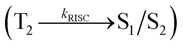 than cold RISC (T1 → S1) in TADF mechanism.21,22 Therefore, hot exciton mechanism with HLCT state increases the ηEQE as a result of coexistence of high ηPL and high ηS.
Based on the above issues, herein we report 4′-(1-(4-morpholinophenyl)-1H-phenanthro[9,10-d]imidazole-2-yl)-styryl-2-(4′-9H-carbazole-9-yl) (MPPIS-Cz) and 4′-(1-(4-morpholinophenyl)-1H-phenanthro[9,10-d]imidazole-2-yl)-styryl-N,N-diphenyl-[1,1′-biphenyl]-4-amine (MPPIS-TPA) shows high fluorescence efficiency. The strong donor triphenylamine (TPA) in MPPIS-TPA is replaced with a weaker electron donating carbazole (Cz) in MPPIS-Cz which is expected to decrease CT component with simultaneous increase of LE component in S1 HLCT state. The ηPL of MPPIS-Cz film is enhanced compared to MPPIS-TPA film and thus combined effect of high ηPL and high ηS enhanced the ηEQE of MPPIS-Cz based device.
2. Experiment and characterization
Sigma-Aldrich supplied all the chemicals for the synthesis of blue emissive materials (Scheme S1†). The 1H and 13C NMR and mass spectra were obtained on Bruker 400 MHz NMR spectrometer and Agilent LCMS VL SD in electron ionization mode, respectively. Cyclic voltammetry (CV) analyses have been carried out to calculate HOMO energy of MPPIS-Cz and MPPIS-TPA by using CHI 630A potentiostat electrochemical analyzer with platinum electrode and platinum wire as the working electrode and counter electrode, respectively. The Ag/Ag+ electrode is used as the reference electrode at a scan rate of 100 mV s−1 with 0.1 M tetrabutylammoniumperchlorate in CH2Cl2 as the supporting electrolyte. The UV-visible spectra were recorded using Perkin Elmer Lambda 35 UV-vis spectrophotometer and corrected for background absorption due to solvent. Perkin Elmer Lambda 35 spectrophotometer with RSA-PE-20 integrating sphere attachment was employed to record UV-vis diffuse reflectance spectra. Photoluminescence spectra were recorded on a Perkin Elmer LS55 fluorescence spectrometer. The PL quantum yield was calculated in dichloromethane with 0.5 M H2SO4 solution of quinine (0.54) as reference using the following equation: where ϕunk and ϕstd are the radiative quantum yield of the sample and standard, Iunk and Istd are the integrated emission intensities of the sample and standard, respectively. Aunk and Astd are the absorbances of the sample and standard, respectively and ηunk and ηstd are the refractive indices of the sample and standard solutions. The solid state quantum yield has been measured on the quartz plate using an integrating sphere. Thermo gravimetric analyses (TGA) was carried out on a Perkin Elmer thermal analysis system at a heating rate of 10 °C min−1 with nitrogen flow rate of 100 mL min−1. Differential scanning calorimetric (DSC) analysis was recorded with NETZSCH (DSC-204) at 10 °C min−1 under nitrogen atmosphere (100 mL min−1).
2.1. Computational details
All the density functional theory (DFT) calculations were carried out using Gaussian 09 package.23 The density functional theory (DFT) and time-dependent DFT (TD-DFT) were carried out for ground state and excited state geometry optimization at the level of B3LYP/6-31G (d, p). In order to examine the nature of electronic transitions for excited states, natural transition orbital (NTOs) are evaluated with the dominant particle–hole pair contributions and the associated weights.23 The out file obtained from the TD-DFT method used to get transition property such as the electron–hole distribution, the overlap of electron–hole of excited states, natural transition orbital and transition density matrix and are analyzed with the multifunctional wave function analyzer (Multiwfn).23![[thin space (1/6-em)]](https://www.rsc.org/images/entities/char_2009.gif) :CH2Cl2, 1:1). M. P. 246 °C. Anal. calcd for C33H27BrN3O: C, 82.30; H, 5.65; Br, 14.83; N, 8.73. Found: C, 82.43; H, 5.68; Br, 14.78; N 8.71. 1H NMR (400 MHz, CDCl3): δ 3.19 (s, 4H), 3.48 (s, 4H), 6.64 (d, J = 8.8 Hz, 1H), 7.11 (d, J = 16.0 Hz, 1H), 7.19 (d, J = 8 Hz, 2H), 7.35–7.46 (m, 4H), 7.47–7.55 (m, 5H), 7.73 (d, J = 17.6 Hz, 1H), 7.82 (d, J = 16.8 Hz, 1H), 8.03 (d, J = 15.5 Hz, 2H), 8.51 (d, 2 J = 14.6 Hz, H), 9.41 (t, 1H). 13C NMR (100 MHz, CDCl3): δ 51.33, 69.42, 115.78, 120.53, 120.96, 121.41, 121.88, 122.22, 122.54, 123.95, 124.22, 124.95, 125.12, 125.80, 125.95, 126.27, 126.36, 126.49, 126.77, 127.09, 127.34, 127.43, 127.64, 128.82, 130.83, 132.35, 147.77. MS: m/z 481.6 [M+]; calcd 481.81.:CH2Cl2, 1:1). Mp 289 °C. Anal. calcd for C45H34N4O: C, 83.57; H, 5.30; N, 8.66. Found: C, 83.46; H, 5.24; N, 8.61. 1H NMR (400 MHz, CDCl3): δ 3.14 (s, 4H), 3.43 (s, 4H), 6.53 (d, J = 16.0 Hz, 1H), 6.58 (d, J = 16.0 Hz, 1H), 6.97–7.13 (m, 5H), 7.16 (d, J = 16.2 Hz, 1H), 7.27–7.41 (m, 7H), 7.48 (s, 2H), 7.53 (d, J = 17.0 Hz, 1H), 7.87–7.94 (m, 4H), 8.07–8.11 (m, 3H), 8.67 (d, J = 14.2 Hz, 2H). 13C NMR (100 MHz, CDCl3): δ 53.68, 71.36, 102.08, 111.28, 113.67, 116.12, 120.08, 121.26, 121.47, 122.58, 122.67, 122.89, 126.07, 126.22, 126.43, 126.87, 126.91, 129.78, 131.82, 132.13, 134.71, 138.36, 140.83, 148.24. MALDI-TOF MS: m/z 645.7 [M+], calcd 646.8.:ethanol (20:15 mL) was refluxed in nitrogen atmosphere for 18 h. The reaction mixture was cooled and extracted with dichloromethane. The extract was concentrated and the residue was purified by column chromatography (petroleum ether:CH2Cl2, 1:1). Mp 275 °C. Anal. calcd for C51H40N4O: C, 84.50; H, 5.56; N, 7.73. Found: C, 84.32; H, 5.36; N, 7.57. 1H NMR (400 MHz, CDCl3): δ 3.27 (s, 4H), 3.54 (s, 4H), 6.69 (s, 2H), 6.98–7.23 (m, 8H), 7.33–7.49 (m, 11H), 7.57 (d, J = 16.8 Hz, 1H), 7.64 (d, J = 18.2 Hz, 1H), 7.98–8.06 (m, 6H), 8.22 (d, J = 17.4 Hz, 1H), 8.79 (s, 2H). 13C NMR (100 MHz, CDCl3): δ 55.72, 73.47, 106.58, 115.32, 117.92, 120.42, 124.87, 125.39, 125.61, 126.43, 126.61, 126.87, 130.32, 130.77, 130.98, 134.73, 136.92, 138.84, 139.91, 142.34, 151.26. MALDI-TOF MS: m/z 723.7 [M+], calcd 724.9.
:CH2Cl2, 1:1). M. P. 246 °C. Anal. calcd for C33H27BrN3O: C, 82.30; H, 5.65; Br, 14.83; N, 8.73. Found: C, 82.43; H, 5.68; Br, 14.78; N 8.71. 1H NMR (400 MHz, CDCl3): δ 3.19 (s, 4H), 3.48 (s, 4H), 6.64 (d, J = 8.8 Hz, 1H), 7.11 (d, J = 16.0 Hz, 1H), 7.19 (d, J = 8 Hz, 2H), 7.35–7.46 (m, 4H), 7.47–7.55 (m, 5H), 7.73 (d, J = 17.6 Hz, 1H), 7.82 (d, J = 16.8 Hz, 1H), 8.03 (d, J = 15.5 Hz, 2H), 8.51 (d, 2 J = 14.6 Hz, H), 9.41 (t, 1H). 13C NMR (100 MHz, CDCl3): δ 51.33, 69.42, 115.78, 120.53, 120.96, 121.41, 121.88, 122.22, 122.54, 123.95, 124.22, 124.95, 125.12, 125.80, 125.95, 126.27, 126.36, 126.49, 126.77, 127.09, 127.34, 127.43, 127.64, 128.82, 130.83, 132.35, 147.77. MS: m/z 481.6 [M+]; calcd 481.81.:CH2Cl2, 1:1). Mp 289 °C. Anal. calcd for C45H34N4O: C, 83.57; H, 5.30; N, 8.66. Found: C, 83.46; H, 5.24; N, 8.61. 1H NMR (400 MHz, CDCl3): δ 3.14 (s, 4H), 3.43 (s, 4H), 6.53 (d, J = 16.0 Hz, 1H), 6.58 (d, J = 16.0 Hz, 1H), 6.97–7.13 (m, 5H), 7.16 (d, J = 16.2 Hz, 1H), 7.27–7.41 (m, 7H), 7.48 (s, 2H), 7.53 (d, J = 17.0 Hz, 1H), 7.87–7.94 (m, 4H), 8.07–8.11 (m, 3H), 8.67 (d, J = 14.2 Hz, 2H). 13C NMR (100 MHz, CDCl3): δ 53.68, 71.36, 102.08, 111.28, 113.67, 116.12, 120.08, 121.26, 121.47, 122.58, 122.67, 122.89, 126.07, 126.22, 126.43, 126.87, 126.91, 129.78, 131.82, 132.13, 134.71, 138.36, 140.83, 148.24. MALDI-TOF MS: m/z 645.7 [M+], calcd 646.8.:ethanol (20:15 mL) was refluxed in nitrogen atmosphere for 18 h. The reaction mixture was cooled and extracted with dichloromethane. The extract was concentrated and the residue was purified by column chromatography (petroleum ether:CH2Cl2, 1:1). Mp 275 °C. Anal. calcd for C51H40N4O: C, 84.50; H, 5.56; N, 7.73. Found: C, 84.32; H, 5.36; N, 7.57. 1H NMR (400 MHz, CDCl3): δ 3.27 (s, 4H), 3.54 (s, 4H), 6.69 (s, 2H), 6.98–7.23 (m, 8H), 7.33–7.49 (m, 11H), 7.57 (d, J = 16.8 Hz, 1H), 7.64 (d, J = 18.2 Hz, 1H), 7.98–8.06 (m, 6H), 8.22 (d, J = 17.4 Hz, 1H), 8.79 (s, 2H). 13C NMR (100 MHz, CDCl3): δ 55.72, 73.47, 106.58, 115.32, 117.92, 120.42, 124.87, 125.39, 125.61, 126.43, 126.61, 126.87, 130.32, 130.77, 130.98, 134.73, 136.92, 138.84, 139.91, 142.34, 151.26. MALDI-TOF MS: m/z 723.7 [M+], calcd 724.9.3. Results and discussion
3.1. Donor–π–acceptor molecular design
4′-(1-(4-Morpholinophenyl)-1H-phenanthro[9,10-d]imidazole-2-yl)-styryl-2-(4′-9H-carbazole-9-yl) (MPPIS-Cz) is composed of carbazole (Cz) as electron donor and morpholinophenylphenanthrimidazole as electron acceptor with styryl as spacer. To improve photoluminance efficiency (ηPL), the strong electron donor TPA moiety in MPPIS-TPA is replaced with weaker donor moiety Cz to decrease the CT component with increase of LE component in the emissive S1 state of MPPIS-Cz. The ground state (S0) and excited state (S1) geometries were optimized using DFT/B3LYP/6-31G (d, p) and TD-DFT/B3LYP/6-31G (d, p) methods for MPPIS-Cz and MPPIS-TPA (Fig. 1). The three key twist angles (TA) exist in MPPIS-TPA and MPPIS-Cz are: θ1 – between phenanthrimidazole plane and styryl at C2) N1-TA, θ2 – between phenanthrimidazole plane and 4-morpholinobenzenamine at N1 and θ3 – between biphenyl fragment in MPPIS-TPA and between styryl phenyl and carbazole ring MPPIS-Cz. In ground state the styryl fragment (θ1) and 4-morpholinobenzenamine (θ2) are highly twisted about phenanthrimidazole plane with dihedral angle of θ1 – 36°; θ2 – 73° for MPPIS-TPA and θ1 – 61°; θ2 – 75° for MPPIS-Cz. The TPA moiety in MPPIS-TPA and Cz moiety in MPPIS-Cz also twisted with dihedral angles of 47° and 45°, respectively.24a The larger twist angle of MPPIS-Cz when compared with MPPIS-TPA is due to the stronger repulsion between the two adjacent hydrogen atoms in carbazole and phenyl ring, as a result of the stronger rigidity of Cz than TPA. The excited state twist angle θ1 of MPPIS-Cz and MPPIS-TPA are increased to 74.15° and 42.56°, respectively, when compared with ground state twist angle θ1. Similarly smaller twist angle θ2 was obtained for MPPIS-Cz when compared with MPPIS-TPA. The bond length (R1) of MPPIS-Cz and MPPIS-TPA are elongated by 0.02 and 0.07 Å, respectively from S0 to S1. The observed smaller change of geometry from S0 to S1 in Cz moiety of MPPIS-Cz than that of TPA unit in MPPIS-TPA may decrease the non radiative emission (knr) results enhancement of photoluminance efficiency. | ||
| Fig. 1 Ground state (S0) and excited state (S1) geometries of MPPIS-TPA and MPPIS-Cz. | ||
The highest occupied molecular orbital (HOMO) and the lowest unoccupied molecular orbital (LUMO) are mainly localized on Cz (MPPIS-Cz) and TPA (MPPIS-TPA) and MPPIS moieties, respectively (Fig. 2). This bipolar molecular design with the balanced carrier transport property is an additional benefit of MPPIS-Cz and MPPIS-TPA molecules as the light emitting layer in which Cz (MPPIS-Cz) and TPA (MPPIS-TPA) acts as hole-transporting group and MPPIS as electron transporting group, respectively. Compared with MPPIS-TPA, the delocalization of HOMO decreases in MPPIS-Cz indicating that the Cz is a weak donor than TPA. The HOMO energy of MPPIS-Cz is decreased by 0.25 eV compared to that of MPPIS-TPA corresponding to the weak electron donating ability of Cz than TPA.
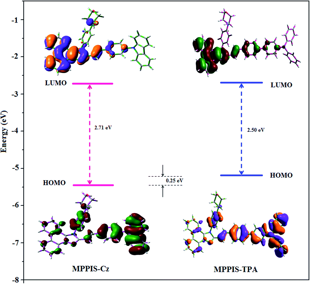 | ||
| Fig. 2 HOMO and LUMO contour map of MPPIS-Cz and MPPIS-TPA. | ||
To understand the nature of excited states, the natural transition orbitals (NTO)24 of MPPIS-Cz and MPPIS-TPA have been analyzed (Fig. 3). For S1 and S2 states, NTO hole and particle distribution in MPPIS-Cz are almost similar to those in MPPIS-TPA. The hole is delocalized over entire molecular backbone whereas particle is localized on MPPIS and styryl fragments. However, similar particle contour is obtained in both MPPIS-Cz and MPPIS-TPA, the hole contour of MPPIS-Cz is shrunk as a result of weaker donor ability of Cz. This indicates an enhanced LE component in S1 state HLCT. The oscillator strength of S1 state of MPPIS-Cz (0.7557) is higher than that of MPPIS-TPA (0.6148) results higher ηPL for MPPIS-Cz than for MPPIS-TPA (Table S1†). Chemical modification from TPA to Cz induces an increase LE component in S1 emissive state together with rigid molecular skeleton. Both S1 and S2 states exhibit a character of hybridized local and charge transfer state (HLCT) in which higher LE character of S1 state enhance the ηPL in MPPIS-Cz. The hole contour on Cz or TPA moiety are in the opposite phase between S1 and S2 states whereas the particle on MPPIS moiety is same between S1 and S2 states for MPPIS-Cz and MPPIS-TPA, respectively. This implied that the interstate hybridization coupling occurs through the positive and negative linear combination between LE and CT state wave function: ΨS1/S2 = cLEΨLE ± cCTΨCT. The percentage of pure CT level of MPPIS-Cz (∼10%) is less than that of MPPIS-TPA (∼20%) as a result of the weak donor ability of Cz than TPA leading to LE dominated S1 state in MPPIS-Cz (LE ∼ 90%) and LE/CT balanced S1 state in MPPIS-TPA (LE ∼ 80%). As a result MPPIS-Cz should exhibit higher photoluminance efficiency (ηPL) and blue shifted emission relative to MPPIS-TPA.
 | ||
| Fig. 3 Computed natural transition orbital pairs for S1–S5 of MPPIS-Cz and MPPIS-TPA [oscillator strength (f): percentage weights of hole–particle]. | ||
The singlet state energies have been estimated at the geometry of S0 state. A large energy gap occurs between T1 and T2 for both MPPIS-Cz and MPPIS-TPA arising from the same MPPIS acceptor group and the energy gap between T1 and T2 of MPPIS-Cz is larger than MPPIS-TPA (Fig. 4a).25,26 A very small ΔEST is observed between S1 and T2 states facilitating RISC (T2 → S1) process in both MPPIS-Cz and MPPIS-TPA as a result of their HLCT state character (Fig. 4b). Thus, compared with MPPIS-TPA, MPPIS-Cz can be expected to obtain high photoluminance efficiency (ηPL) and high exciton utilisation efficiency (ηS) and further to enhance the external quantum efficiency (ηEQE) of the fluorescent OLED as a result of increased LE component in S1 state.
 | ||
| Fig. 4 (a) Energy level of singlet (S) and triplet (T) states of MPPIS-Cz and MPPIS-TPA; (b) scheme of exciton decay process after hole and electron recombination in OLEDs of twisting D–π–A molecules. | ||
The eigen value for all states is greater than 0.98 which also indicate that the better mixed excited state can be described in terms of dominant excitation pair according to 98% of the transition which is further supported by overlap integral (Δr index – eqn (S1)) which is greater than two for all singlet and triplet states of MPPIS-TPA and less than two for MPPIS-Cz (Table S2†). The Δr index measures the average hole–electron distance upon excitation and it is related to the nature of the excitation type (LE or CT) since valence excitation (LE) is characterized by short distances while larger distances are found for CT excitations.
The formation of HLCT state can be analysed computationally by using excitation energies of LE and CT states (Scheme S2 and Table S2†). Due to extended π-conjugation in MPPIS-TPA, the CT state is stabilised than LE state and the reduced energy gap leading to full hybridisation of LE and CT states which inturn improves the OLED efficiency. However, in MPPIS-Cz the LE state is stabilised than CT state and the energy gap is high when compared with MPPIS-TPA results partial hybridisation (Scheme S2†). The overlap between hole and particle of MPPIS-Cz and MPPIS-TPA is displayed in Fig. S1.† Further, the composition of HLCT can also analysed computationally from the wave function of electron–hole pairs transition density matrix (TDM) and plot them in two dimension colour-filled map (Fig. S2 and S3†). The axes represent the atom in a molecule which is related to the probability of finding the electron and hole in the atomic orbitals localized on each non-hydrogen atom: the diagonal part represents the LE component localized on the main backbone while the off-diagonal region denotes the CT component. This further supports that the HLCT state also contributes to the hybridization apart from LE and CT states.27 Upon excitation the electron is transferred from the donor and localized on the acceptor. Depending upon the intramolecular geometrical and electronic coupling the transferred electron is delocalized from the region of the nearby donor molecule to the vicinity of the acceptor. This effect can be qualitatively studied by the analysis of the density distribution at the ground and the excited states.28,29
Computed electron–hole properties, transition density and distance between hole and electron (DH–E), RMSD of electron and hole, H and t indices of MPPIS-Cz and MPPIS-TPA are displayed in Tables S3 and S4.† The integral value of hole and electron of MPPIS-Cz is less than that of MPPIS-TPA and the integral overlap of hole electron distribution (SH–E) is a measure of spatial separation of hole and electron. The SH–E and DH–E values supports the existence of LE and CT states. When compared with MPPIS-TPA, MPPIS-Cz has small DH–E and high SH–E values which indicates the charge transfer (CT) is higher in percentage for MPPIS-TPA isomer (Table S3†). RMSD of hole or electron characterizes the charge transfer distribution breadth. Table S4† show that the RMSD of MPPIS-Cz is higher in X direction for S1–S5 states which indicates the electron and hole distribution is much broader in X direction. The similar trend is observed for MPPIS-TPA but the total RMSD of hole and electron is higher for MPPIS-Cz than MPPIS-TPA. Table S5† summarises DCT, qCT, μCT, barycenter of charges (R+ and R−) and two CT indexes (H and t). The DCT of MPPIS-Cz and MPPIS-TPA is calculated to be 0.459 and 0.607, respectively (Fig. 5). Distance between centroid of hole and electron (DCT) is a measure of CT length: larger the DCT, longer length is the charge transfers in the MPPIS-Cz and MPPIS-TPA. The CT length measures the distance between the barycenters (DCT) and the transferred charges (qCT) by the integration of the density depletion functions. The H index measures the spread of the positive and negative regions related to CT and t index is the difference between DCT and H index (eqn (S15) and (S16)†). For both MPPIS-Cz and MPPIS-TPA, t is greater than zero and it is negative in all directions. This reveals that the overlap of hole and electron is very severe. Using the total electron density computed for the ground and excited states, it is possible to evaluate Δρ, ρ+, and ρ− on a grid points around MPPIS-Cz and MPPIS-TPA (eqn (S2)–(S4),† Fig. 5). The green and blue zones corresponding to the centroids of charges (eqn (S9) and (S10)†) ρ+ and ρ−, respectively: the density depletion (blue) zones are mostly located on the TPA and Cz donor groups and the regions of density increment (green) are localized on the acceptor phenanthrimidazole moiety. The barycenter of charges (R+ and R−) are calculated according to the eqn (S5) and (S6):† R− barycenter is close to the pheanthrimidazole group and R+ barycenter is close to Cz and TPA. The computed change in dipolemoment (μCT) between the ground and excited states is determined using DCT and qCT (eqn (S8)†). The computed overlap between the ρ+ and ρ− regions for MPPIS-Cz and MPPIS-TPA as 0.9939 and 0.9795, respectively (Table S5†).
 | ||
| Fig. 5 Computed difference in total density for ground and excited states [Δρ(r) = ρEx(r) − ρGs(r); isosurface value for MPPIS-Cz (0.0500 a.u) and for MPPIS-TPA (0.0010 a.u)]; graphical representation of DCT and centroids of charges [C+(r)/C−(r); isosurface value for MPPIS-Cz (0. 29 a.u) and for MPPIS-TPA (0.1 a.u)]. | ||
3.2. Electrochemical, thermal and photophysical properties
From the cyclic voltammogram of MPPIS-Cz and MPPIS-TPA, the HOMO and LUMO energies have been calculated (Fig. 6a). The LUMO energies of both MPPIS-Cz (−2.73 eV) and MPPIS-TPA (−2.69 eV) are nearly same which is attributed to their same acceptor MPPIS unit. The HOMO energy −5.34 eV of MPPIS-Cz is lower than that of MPPIS-TPA (−5.19 eV) corresponding to that of Cz and TPA group, respectively. The decreased HOMO energy of MPPIS-Cz is due to the poor electron donating ability of Cz relative to TPA and this observation was supported by DFT calculation. The thermal properties of blue light emitting materials (MPPIS-Cz and MPPIS-TPA) have been analysed to understand the device stability. For MPPIS-Cz, the glass transition temperature (Tg) and thermal decomposition temperature (Td) were measured as 156 and 438 °C which are higher than that of MPPIS-TPA (Tg – 128 and Td – 426 °C) (Fig. 6b). The higher thermal stability of MPPIS-Cz is due to the stronger rigidity of Cz than TPA which will be in favour of OLED stability. | ||
| Fig. 6 (a) Cyclic voltammogram of MPPIS-Cz and MPPIS-TPA; (b) DSC and TGA graphs of MPPIS-TPA and MPPIS-Cz. | ||
UV-vis spectra show the absorption peak at 328 and 350 nm for MPPIS-Cz and MPPIS-TPA, respectively and their emission maxima was observed at 420 and 444 nm in dichloromethane solution (Fig. 7a). Compared with MPPIS-TPA, MPPIS-Cz exhibit blue shift for both UV-vis (22 nm) and PL (24 nm) which can be attributed to the poor electron donor ability of Cz relative to TPA results an increased LE component with simultaneous decrease of CT component in S1 emissive state. The full width at half maximum in absorption spectrum of MPPIS-Cz (40 nm) is narrowed relative to that of MPPIS-TPA (50 nm). This observation also indicates that the decrease of CT component in S1 state of MPPIS-Cz which is in good agreement with NTO description for S0 → S1 transition. Furthermore, both UV-vis and PL spectra of MPPIS-Cz and MPPIS-TPA have been measured in vacuum evaporated film. UV-vis and PL spectra of MPPIS-Cz in solid film (UV – 320 nm; PL – 436 nm) show a significant blue shift when compared with MPPIS-TPA (UV – 342; PL – 446 nm). The larger twist angle of θ1 in the ground state of MPPIS-Cz may weaken the intermolecular interactions and decrease the molecular aggregation results increase of photoluminance efficiency (ηPL) through the suppression of aggregation induced fluorescence quenching.30a
 | ||
| Fig. 7 (a) Normalized absorption and emission spectra of MPPIS-Cz and MPPIS-TPA in dichloromethane and film; (b) Lippert–Mataga plot of MPPIS-Cz and MPPIS-TPA in different solvents. | ||
The intramolecular charge transfer of both MPPIS-Cz and MPPIS-TPA in excited states have been analysed by solvatochromic effect.13,14 The fluorescence of MPPIS-Cz exhibits solvatochromic effect with increase of solvent polarity and the total red shift of 70 nm is smaller than that of MPPIS-TPA (90 nm) (Fig. S4†). Similarly a small shift of 15 nm and 18 nm for MPPIS-Cz and MPPIS-TPA, respectively, has been observed in the absorption spectra (Fig. S4†). The solvatochromic shifts reveal that the low lying excited state S1 of the MPPIS-Cz and MPPIS-TPA must possesses certain CT state character.30,31 The percentage of CT character in S1 state of MPPIS-Cz is lower than that in MPPIS-TPA and the percentage of LE character for MPPIS-Cz is higher than that in MPPIS-TPA. The quantum yield of MPPIS-TPA (ϕsol/film: 0.71/0.60) is higher than that of MPPIS-Cz (ϕsol/film: 0.61/0.58) as a result of the enhanced LE component in emissive state. A similar trend is observed from low polar to high polar solvent indicates the less percentage of CT in MPPIS-Cz than that in MPPIS-TPA.
The excited state dipole moment (μe) of MPPIS-Cz and MPPIS-TPA have been calculated from the Lippert–Mataga plot of Stokes shift (νa − νf) against orientation polarizability, f(ε,n) (Fig. 7b) (Tables S6 and S7†).32 Both compounds show two independent slopes of two section fitted lines which reveal the existence of two different characters of excited state.33 The dipolemoment was calculated to be 24.9 (R2 − 0.87) and 9.9D (R2 − 0.91) (MPPIS-Cz) and 23.8 (R2 − 0.96) and 12.1D (R2 − 0.87) (MPPIS-TPA) for high and low polar solvents, respectively. In low-polar solvents, the dipole moment of 9.9D (MPPIS-Cz) and 12.1D (MPPIS-TPA) reveal that the S1 state possessed CT character in addition to LE. The quantum yield of both MPPIS-Cz and MPPIS-TPA decreases with increasing solvent polarity and relatively high quantum yield was obtained between hexane and butyl ether. These factors demonstrated that certain degree of locally excited (LE) character has been introduced thus, S1 state in low polar solvents contained both CT and LE components. However, observation of single-exponential fluorescence decay (Fig. 8a) for MPPIS-Cz and MPPIS-TPA in low polar solvents reveal that a new and unique excited state i.e., hybridized local and charge-transfer (HLCT) state exists in the D–π–A architecture rather than a mixture of LE and CT states.34,35 In low polarity solvent, the smaller μe of MPPIS-Cz relative to MPPIS-TPA can be ascribed to weak donor ability of Cz than TPA corresponding to the higher LE proportion as expected in molecule design of MPPIS-Cz.
 | ||
| Fig. 8 (a) Lifetime decay curve; (b) AFM images based film at room temperature of MPPIS-Cz and MPPIS-TPA. | ||
The two section linear relation between Stokes shift and solvent polarity indicating that both MPPIS-Cz and MPPIS-TPA possess an intercrossed excited state of LE and CT: a higher contribution from CT state in high polarity solvents (f ≥ 0.2), whereas a dominant contribution from LE state in low polarity solvents (f ≤ 0.1). The intercrossed excited state of the LE and CT may occur in a moderate polarity between butyl ether and ethyl acetate. The hybridized local and charge transfer (HLCT) state forms due to the intercrossing coupling between LE and CT states. The lifetime measurement reveals that this intercrossed excited state in different polar solvents should be a hybridized local and charge transfer state (HLCT) instead of two species state through a simple addition of LE and CT (Scheme S2†).
The time correlated single photon counting (TCSPC) results fit to mono exponential decay, f(t) = aexp(−t/τ), where α and τ are respectively, the pre-exponential factor and lifetime of the various excited states involved. If Ni molecules are excited at zero time, the quantum yield of the ith component αi is proportional to the ratio αiτi/Ni and the αi factors are related to the absorbance of the various substances at the excitation wavelength. Laser excitation was set at 270 nm and the fluorescence signal was measured at emission wavelength of individual compound. DAS6 software was used for the fit and the χ2 values are less than 1.2. The mono exponential lifetime demonstrates that the intercrossed LE and CT in the moderate polarity solvent formed as one hybridized HLCT state which supports the molecular design (Fig. 8a). The emission wavelength of both MPPIS-Cz and MPPIS-TPA in film is close to that in ethyl ether which supports the HLCT state formed in MPPIS-Cz and MPPIS-TPA film. The radiative transition rate (kr) and the non-radiative transition rate (knr) of MPPIS-Cz and MPPIS-TPA have been calculated from lifetime and quantum yield. Compared with MPPIS-TPA, the kr of MPPIS-Cz is increased and knr of MPPIS-Cz is decreased (Fig. S5†). This result is also in good agreement with the aim of our molecular design.
3.3. Electroluminescence properties
The effective film formatting properties of light emitting materials are important for device efficiency. The surface morphologies of vacuum deposited thin film of MPPIS-Cz and MPPIS-TPA have been studied by atomic force microscopy (AFM) topography images and the root-mean-square (RMS) roughness is 0.31 and 0.38 nm, respectively. The thin film of MPPIS-Cz exhibit lowest RMS which results high efficiency (Fig. 8b). To evaluate the EL performances of MPPIS-Cz and MPPIS-TPA, non-doped OLEDs were fabricated with a device structure: ITO/N,N′-di-1-naphthyl-N,N′-diphenylbenzidine (NPB) (70 nm)/MPPIS-Cz or MPPIS-TPA (20 nm)/1,3,5-tri(phenyl-2-benzimidazolyl)-benzene (TPBi) (20 nm)/LiF (0.5 nm)/Al (100 nm). Compared with MPPIS-TPA, MPPIS-Cz based device shows a maximum luminous efficiency of 1.52 cd A−1 and maximum luminance of 4801 cd m−2. Based on the external quantum efficiency-luminance characteristics of the two devices, the MPPIS-Cz device harvests a maximum external quantum efficiency of 1.48% and power efficiency of 1.30 lm W−1 (Table 1; Fig. 9). The calculated internal quantum efficiency (ηIQE) of MPPIS-Cz and MPPIS-TPA are to be 7.4% and 6.7%, respectively and the exciton utilisation efficiency are to be 12.3% and 11.6%, respectively. The current and power efficiencies of the devices based on MPPIS-Cz (1.52 cd A−1; 1.30 lm W−1) and MPPIS-TPA (1.46 cd A−1; 1.28 lm W−1) are higher than those of the devices based on TPA-PA (1.16 cd A−1; 0.65 lm W−1), TPA-NzP (1.00 cd A−1; 0.77 lm W−1)19 and mTPA-PPI (0.84 cd A−1; 0.48 lm W−1).19b Also the external quantum yield of MPPIS-Cz (71%) and MPPIS-TPA (61%) are higher than those of (i) Cz-BzP (69.7%) and TPA-BzP (49.2%)30a (ii) CBI (21%) and MCB (24%)19c and (iii) PPI-pCNCz (54%).30b Wang et al.,30c report that the thickness of the LBPPI emissive layer alters the current efficiency (50 nm – 0.01 cd A−1; 40 nm – 0.13 cd A−1; 30 nm – 0.40 cd A−1 and 20 nm – 0.68 cd A−1).32d The current efficiency obtained in the present study with thickness of 20 nm of MPPIS-Cz (1.52 cd A−1) and 20 nm of MPPIS-TPA (1.46 cd A−1) is higher than those reported by Wang et al. Hence it is possible to improve the efficiency of these materials through modification of thickness of the emissive layer. Effort will be made to modify the thickness of the emissive layer to enhance the efficiency and also effort will made to increase the radiative rate in future of our studies. The weaker donor carbazole substituted phenanthrimidazole exhibit current efficiency of 0.88 cd A−1 and power efficiency of 0.30 lm W−1 (ref. 32e) and Gao et al., reported carbazole substituted compound with current efficiency of 0.65 cd A−1 and 0.48 lm W−1.32c These carbazole substituted compound exhibit less efficiencies than those obtained in our studies MPPIS-Cz (1.52 cd A−1; 1.30 lm W−1) and MPPIS-TPA (1.46 cd A−1; 1.28 lm W−1). The device efficiency indicates that MPPIS-Cz is one of the best fluorescent OLEDs materials.| Parameters | MPPIS-Cz | MPPIS-TPA |
|---|---|---|
| a ηc – luminous efficiency; ηp – power efficiency; ηEQE – external quantum efficiency; EL – electroluminescence.b ηIQE – maximum internal quantum efficiency; (ηIQE = ηEQE/ηout).c ηs – light out coupling efficiency (ηIQE/ηPL). | ||
| V1000 (V) | 5.2 | 6.1 |
| L (cd m−2) | 4801 | 3858 |
| ηex (%) | 1.48 | 1.34 |
| ηc (cd A−1) | 1.52 | 1.46 |
| ηp (lm W−1) | 1.30 | 1.28 |
| EL (nm) | 430 | 435 |
| CIE (x, y) | 0.16, 0.08 | 0.15, 0.12 |
| ηIQE (%)b | 7.4 | 6.7 |
| ηs (%)c | 11.7 | 11.6 |
 | ||
| Fig. 9 Electroluminescence performances: (a) luminance versus voltage; (b) external quantum efficiency versus current density; (c) current efficiency and power efficiency versus current density of non-doped EL device with MPPIS-TPA and MPPIS-Cz as emitter. | ||
4. Conclusion
We have synthesized fluorescent D–π–A molecules, MPPIS-Cz and MPPIS-TPA possess HLCT state to obtain maximum EL efficiency through high PL efficiency and high exciton utilization in fluorescent OLED. The photophysical, film morphology and electrochemical properties of MPPIS-Cz and MPPIS-TPA can be tuned by chemical modification from MPPIS-TPA to MPPIS-Cz by changing the strong donor TPA moiety by weak donor Cz moiety. This results HLCT as the emissive state with increased LE and decreased CT which in turn increased the quantum efficiency. The external quantum efficiency of non-doped device based on MPPIS-Cz is 1.48% and its radiative rate is 12.2 × 10⁶ s−1. This is probably as a result of efficient RISC (T2 → S1) through hot exciton process. The MPPIS-Cz based non-doped fluorescent OLED show a CIE coordinates of (0.16, 0.08), maximum current efficiency of 1.52 cd A−1, maximum external quantum efficiency of 1.48% and power efficiency 1.30 lm W−1. These results are helpful to design the next generation efficient low cost fluorescent OLED materials using HLCT state principle and hot exciton model.Acknowledgements
One of the author Dr J. Jayabharathi thank Department of Science and Technology (EMR/2014/000094), Defence Research and Development Organization (213/MAT/10-11), Council of Scientific and Industrial Research [No. 01/(2707)/13EMR-II], University Grant Commission (36-21/2008) and Nano Mission (SR/NM/NS-1001/2016) for financial support.References
- (a) C. Chein, C. Chen, F. Hsu, C. Shu, P. Chou and C. Lai, Adv. Funct. Mater., 2009, 19, 560–566 CrossRef; (b) C. H. Chang, M. C. Kuo, W. C. Lin, Y. T. Chen, K. T. Wong, S. H. Chou, E. Mondal, R. C. Kwong, S. Xia, T. Nakagawa and C. Adachi, J. Mater. Chem., 2012, 22, 3832–3838 RSC.
- D. H. Kim, N. S. Cho, H. Y. Oh, J. H. Yang, W. S. Jeon, J. S. Park, M. C. Suh and J. H. Kwon, Adv. Mater., 2011, 23, 2721–2726 CrossRef CAS PubMed.
- (a) H. Fukagawa, T. Shimizu, H. Hanashima, Y. Osada, M. Suzuki and H. Fujikake, Adv. Mater., 2012, 24, 5099–5103 CrossRef CAS PubMed; (b) Y. Cho and J. Lee, Adv. Mater., 2011, 23, 4568–4572 CrossRef CAS PubMed.
- (a) M. T. Lee, H. H. Chen, C. H. Liao, C. H. Tsai and C. H. Chen, Appl. Phys. Lett., 2004, 85, 3301–3303 CrossRef CAS; (b) M. T. Lee, C. H. Liao, C. H. Tsai and C. H. Chen, Adv. Mater., 2005, 17, 2493–2497 CrossRef CAS.
- (a) A. Kraft, A. C. Grimsdale and A. B. Holmes, Angew. Chem., Int. Ed., 1998, 37, 402–428 CrossRef; (b) H. Sasabe, N. Toyota, H. Nakanishi, T. Ishizaka, Y. J. Pu and J. Kido, Adv. Mater., 2012, 24, 3212–3217 CrossRef CAS PubMed; (c) H. Huang, Y. X. Wang, S. Q. Zhuang, X. Yang, L. Wang and C. L. Yang, J. Phys. Chem. C, 2012, 116, 19458–19466 CrossRef CAS.
- J. Hu, Y. Pu, F. Satoh, S. Kawata, H. Katagiri, H. Sasabe and J. Kido, Adv. Mater., 2014, 24, 2064–2071 CAS.
- T. C. Chao, Y. T. Lin, C. Y. Yang, T. S. Hung, H. C. Chou, C. C. Wu and K. T. Wong, Adv. Mater., 2005, 17, 992–996 CrossRef CAS.
- J. R. Sheats, H. Antoniadis, M. Hueschen, W. Leonard, J. Miller, R. Moon, D. Roitman and A. Stocking, Science, 1996, 273, 884–888 CAS.
- (a) H. Uoyama, K. Goushi, K. Shizu, H. Nomura and C. Adachi, Nature, 2012, 492, 234–235 CrossRef CAS PubMed; (b) Q. Zhang, B. Li, S. Huang, H. Nomura, H. Tanaka and C. Adachi, Nat. Photonics, 2014, 8, 326–332 CrossRef CAS; (c) H. Tanaka, K. Shizu, H. Miyazaki and C. Adachi, Chem. Commun., 2012, 48, 11392–11394 RSC; (d) Q. Zhang, J. Li, K. Shizu, S. Huang, S. Hirata, H. Miyazaki and C. Adachi, J. Am. Chem. Soc., 2012, 134, 14706–14709 CrossRef CAS PubMed.
- S. P. Jagtap, S. Mukhopadhyay, V. Coropceanu, G. L. Brizius, J. Bredas and D. M. Collard, J. Am. Chem. Soc., 2012, 134, 7176–7185 CrossRef CAS PubMed.
- Z. R. Grabowski, K. Rotkiewicz and W. Rettig, Chem. Rev., 2003, 103, 3899–4031 CrossRef PubMed.
- S. Zhang, L. Yao, Q. Peng, W. Li, Y. Pan, R. Xiao, Y. Gao, C. Gu, Z. Wang, P. Lu, F. Li, S. Su, B. Yang and Y. Ma, Adv. Funct. Mater., 2015, 25, 1755–1762 CrossRef CAS.
- W. J. Li, D. D. Liu, F. Z. Shen, D. G. Ma, Z. M. Wang, T. Fei, B. Yang and Y. G. Ma, Adv. Funct. Mater., 2012, 22, 2797–2803 CrossRef CAS.
- W. J. Li, Y. Y. Pan, R. Xiao, Q. M. Peng, S. T. Zhang, D. G. Ma, F. Li, F. Z. Shen, Y. H. Wang, B. Yang and Y. G. Ma, Adv. Funct. Mater., 2014, 24, 1609–1614 CrossRef CAS.
- S. Tang, W. J. Li, F. Z. Shen, D. D. Liu, B. Yang and Y. G. Ma, J. Mater. Chem., 2012, 22, 4401–4408 RSC.
- S. T. Zhang, W. J. Li, L. Yao, Y. Y. Pan, B. Yang and Y. G. Ma, Chem. Commun., 2013, 49, 11302–11304 RSC.
- L. Yao, S. T. Zhang, R. Wang, W. J. Li, F. Z. Shen, B. Yang and Y. G. Ma, Angew. Chem., Int. Ed., 2014, 126, 2151–2155 CrossRef.
- Y. Y. Pan, W. J. Li, S. T. Zhang, L. Yao, C. Gu, H. Xu, B. Yang and Y. G. Ma, Adv. Opt. Mater., 2014, 2, 510–515 CrossRef CAS.
- (a) W. J. Li, Y. Y. Pan, L. Yao, H. C. Liu, S. T. Zhang, C. Wang, F. Z. Shen, B. Yang and Y. G. Ma, Adv. Opt. Mater., 2014, 2, 892–910 CrossRef CAS; (b) H. Liu, Q. Bai, L. Yao, H. Zhang, H. Xu, S. Zhang, W. Li, Y. Gao, J. Li, P. Lu, H. Wang, B. Yang and Y. Mac, Chem. Sci., 2015, 6, 3797–3804 RSC; (c) N. Nagarajan, G. Velmurugan, G. Prabhu, P. Venuvanalingam and R. Renganathan, J. Lumin., 2014, 147, 111–120 CrossRef CAS.
- D. Chaudhuri, E. Sigmund, A. Meyer, L. Rcck, P. Klemm, S. Lautenschlager, A. Schmid, S. R. Yost, T. Van, S. Bange, S. Hcger and J. M. Lupton, Angew. Chem., 2013, 125, 13691–13694 CrossRef.
- M. A. Baldo, S. Lamansky, P. E. Burrows, M. E. Thompson and S. R. Forrest, Appl. Phys. Lett., 1999, 60, 14422–14428 CAS.
- T. Forster, 10th Spiers Memorial Lecture, Discuss. Faraday Soc., 1959, 27, 7–17 RSC.
- (a) M. J. Frisch, G. W. Trucks, H. B. Schlegel, G. E. Scuseria, M. A. Robb, J. R. Cheeseman, J. A. Montgomery, T. Vreven, K. N. Kudin, J. C. Burant, J. M. Millam, S. S. Iyengar, J. Tomasi, V. Barone, B. Mennucci, M. Cossi, G. Scalmani, N. Rega, G. A. Petersson, H. Nakatsuji, M. Hada, M. Ehara, K. Toyota, R. Fukuda, J. Hasegawa, M. Ishida, T. Nakajima, Y. Honda, O. Kitao, H. Nakai, M. Klene, X. Li, J. E. Knox, H. P. Hratchian, J. B. Cross, V. Bakken, C. Adamo, J. Jaramillo, R. Gomperts, R. E. Stratmann, O. Yazyev, A. J. Austin, R. Cammi; C. Pomelli, J. W. Ochterski, P. Y. Ayala, K. Morokuma, G. A. Voth, P. Salvador, J. J. Dannenberg, V. G. Zakrzewski, S. Dapprich, A. D. Daniels, M. C. Strain, O. Farkas, D. K. Malick, A. D. Rabuck, K. Raghavachari, J. B. Foresman, J. V. Ortiz, Q. Cui, A. G. Baboul, S. Clifford, J. Cioslowski, B. B. Stefanov, G. Liu, A. Liashenko, P. Piskorz, I. Komaromi, R. L. Martin, D. J. Fox, T. Keith, M. A. Al-Laham, C. Y. Peng, A. Nanayakkara, M. Challacombe, P. M. W. Gill, B. Johnson, W. Chen, M. W. Wong, C. Gonzalez and J. A. Pople, Gaussian 03 (Revision E.01), Gaussian, Inc., Wallingford, CT., 2004 Search PubMed; (b) T. Lu and F. Chen, J. Comput. Chem., 2012, 33, 580–592 CrossRef CAS PubMed.
- (a) Y. Zhang, S. L. Lai, Q. X. Tong, M. F. Lo, T. W. Ng, M. Y. Chan, Z. C. Wen, J. He, K. S. Jeff, X. L. Tang, W. M. Liu, C. C. Ko, P. F. Wang and C. S. Lee, Chem. Mater., 2012, 24(1), 61–70 CrossRef; (b) R. Kim, S. Lee, K. H. Kim, Y. J. Lee, S. K. Kwon, J. J. Kim and Y. H. Kim, Chem. Commun., 2013, 49, 4664–4666 RSC.
- M. R. Zhu and C. L. Yang, Chem. Soc. Rev., 2013, 42, 4963–4976 RSC.
- H. H. Chou, Y. H. Chen, H. P. Hsu, W. H. Chang, Y. H. Chen and C. H. Cheng, Adv. Mater., 2012, 24, 5867–5871 CrossRef CAS PubMed.
- J. Liu, Y. Zhang and W. Liu, J. Chem. Theory Comput., 2014, 10, 2436–2448 CrossRef CAS PubMed.
- J. Fortage, C. Peltier, F. Nastasi, F. Puntoriero, F. Tuyeres, S. Griveau, F. Bedioui, S. Campagna and P. P. Laine, J. Am. Chem. Soc., 2010, 132, 16700–16713 CrossRef CAS PubMed.
- C. Peltier, C. Adamo, P. P. Laine, S. Campagana, F. Punteriero and I. Ciofini, J. Phys. Chem. A, 2010, 114, 8434–8443 CrossRef CAS PubMed.
- (a) C. Wang, X. Li, Y. Pan, S. Zhang, L. Yao, Q. Bai, W. Li, P. Lu, B. Yang, S. J. Su and Y. Ma, ACS Appl. Mater. Interfaces, 2016 Search PubMed; (b) B. Wang, X. Lv, J. Tan, Q. Zhang, Z. Huang, W. Yi and L. Wang, J. Mater. Chem. C, 2016, 4, 8473–8482 RSC; (c) Z. Wang, P. Lu, S. Chen, Z. Gao, F. Shen, W. Zhang, Y. Xu, H. S. Kwok and Y. Ma, J. Mater. Chem., 2011, 21, 5451–5456 RSC; (d) Y. Zou, J. H. Zou, T. L. Ye, H. Li, C. L. Yang, H. B. Wu, D. G. Ma, J. G. Qin and Y. Cao, Adv. Funct. Mater., 2013, 23, 1781–1788 CrossRef CAS.
- C. Liu, Q. Fu, Y. Zou, C. L. Yang, D. G. Ma and J. G. Qin, Chem. Mater., 2014, 26, 3074–3083 CrossRef CAS.
- (a) Z. Wang, P. Lu, S. Chen, Z. Gao, F. Shen, W. Zhang, Y. Xu, H. S. Kwok and Y. Ma, J. Mater. Chem., 2011, 21, 5451–5456 RSC; (b) H. Huang, Y. Wang, B. Wang, S. Zhuang, B. Pan, X. Yang, L. Wang and C. Yang, J. Mater. Chem. C, 2013, 1, 5899–5907 RSC; (c) Z. Gao, Y. Liu, Z. Wang, F. Shen, H. Liu, G. Sun, L. Yao, Y. Lv, P. Lu and Y. Ma, Chem.–Eur. J., 2013, 19, 2602–2605 CrossRef CAS PubMed; (d) Z. Wang, Y. Feng, H. Li, Z. Gao, X. Zhang, P. Lu, P. Chen, Y. Ma and S. Liu, Phys. Chem. Chem. Phys., 2014, 16, 10837–10843 RSC; (e) Z. Gao, Z. Wang, T. Shan, Y. Liu, F. Shen, Y. Pan, H. Zhang, X. He, P. Lu, B. Yang and Y. Ma, Org. Electron., 2014, 15, 2667–2676 CrossRef CAS; (f) Z. Gao, G. Cheng, F. Shen, S. Zhang, Y. Zhang, P. Lu and Y. Ma, Laser Photonics Rev., 2014, 8, L6–L10 CrossRef CAS.
- (a) V. E. Z. Lippert, Electrochemistry, 1957, 61, 962–975 Search PubMed; (b) N. Mataga, Y. Kaifu and M. Koizumi, Bull. Chem. Soc. Jpn., 1956, 29, 465–470 CrossRef CAS.
- (a) C. J. Chiang, A. Kimyonok, M. K. Etherington, G. C. Griffiths, V. Jankus, F. Turksoy and A. P. Monkman, Adv. Funct. Mater., 2013, 23, 739–746 CrossRef CAS; (b) D. Y. Kondakov, T. D. Pawlik, T. K. Hatwar and J. P. Spindler, J. Appl. Phys., 2009, 106, 124510–124517 CrossRef.
- R. L. Martin, J. Chem. Phys., 2003, 118, 4775–4777 CrossRef CAS.
Footnote |
| † Electronic supplementary information (ESI) available. See DOI: 10.1039/c6ra28303a |
| This journal is © The Royal Society of Chemistry 2017 |