
 Open Access Article
 This Open Access Article is licensed under a
 Creative Commons Attribution 3.0 Unported Licence
A general strategy for controllable synthesis of Ba3(MO4)2:Mn5+ (M = V, P) nanoparticles
Xiaowen Zhang ,
Yang Li,
Zhongliang Hu,
Zhi Chen and
Jianrong Qiu*
,
Yang Li,
Zhongliang Hu,
Zhi Chen and
Jianrong Qiu*
State Key Laboratory of Luminescent Materials and Devices, Institute of Optical Communication Materials, School of Materials Science and Engineering, South China University of Technology, Guangzhou 510640, P. R. China. E-mail: qjr@scut.edu.cn; Fax: +86-20-87114204; Tel: +86-20-87113646
First published on 8th February 2017
Abstract
The second near-infrared window (NIR-II, 1000–1400 nm) is ideal for fluorescence imaging owing to negligible tissue scattering and minimal autofluorescence. NIR-II luminescence nanophosphors are promising materials for fluorescence imaging. Mn5+ is emerging as a new luminescent indicator owing to its typical NIR-I (800 nm) to NIR-II (1190 nm) downconversion luminescence. Herein, we report a facile synthesis approach to prepare Mn5+ doped Ba3(MO4)2 (M = V, P) nanoparticles with a remarkably sharp emission peak around 1190 nm in the NIR-II region for the first time to our knowledge. The developed two-step approach based on efficient anion exchange reaction is able to not only stabilize the valence but also keep the controlled morphology and uniform size. It is highly possible that the general approach will provide a new perspective on synthesizing special valence ion doped nanosized materials.
1. Introduction
Recently, a large amount of attention has been devoted to the investigation of fluorescence imaging, which provides visible information about disease with high sensitivity and fast feedback.1,2 Biological tissues such as skin and blood scatter and absorb less near-infrared (NIR) light than visible light so that the light in the NIR biological window can penetrate these tissues more efficiently.3 In the past years, extensive investigation has been focused on fluorescent probes emitting in the conventional near-infrared biological window (NIR-I, wavelength of 700–1000 nm).4–6 Recently, it has been demonstrated that the phosphors for emission in the second near-infrared biological window (NIR-II, wavelength of 1000–1400 nm) and excitation in the NIR-I are optimal for the fluorescence imaging of live animals owing to their lower background noise, greater tissue penetration depth, and reduced photon scattering and photo damage effects.7,8 Therefore, they are expected to become more desirable in biological imaging. Up to now, numerous bioluminescence probes emitting in the NIR-II region have been developed, such as quantum dots,9 carbon nanotubes,10 and lanthanide doped nanomaterials.11 However, most of those probes suffer from poor photostability, short luminescence lifetime, poor biocompatibility, high toxicity and even high cost.12 Therefore, their further application is still limited and it is desirable to develop a novel NIR-II luminescence probe for fluorescence imaging.Mn5+, a transition-metal ion with 3d2 electron configuration, is stabilized in a tetrahedral coordination environment, where it has the 1E state below the 3T2 state, giving rise to a longer-lived NIR emission in the 1000–1400 nm region.13 Mn5+ doped phosphate and vanadate are considered promising candidates for solid-state lasers owing to their long fluorescence lifetime, the strong absorption and effective stimulated emission cross section in the near-infrared region.14–16 These unique optical characteristics also enable Mn5+ doped vanadate and phosphate as potentially ideal bio-probes. So far, there still have been no reports about the application of these materials in fluorescence imaging because not only is Mn5+ rare but also Mn5+ doped nanosized materials are difficult to synthesize through traditional chemical routes. Mn5+ is an unstable ion and valence reduction often occurs during synthesis in aqueous solution, resulting in the formation of undesired MnO2 precipitate. Although doping with Mn5+ has been achieved through solid-state reaction under atmosphere control in previous studies,17 it is still impractical to control the particle size and morphology via this route. In addition, high reaction temperature and long reaction time are required in the whole preparation process. To the best of our knowledge, nanosized materials with Mn5+ as the fluorescence center have never been reported. Therefore, it is highly desirable to develop a general but low-cost route to fabricate Mn5+ doped nanoparticles.
In this work, we demonstrate a strategy to fabricate for the first time, we believe, Mn5+ doped Ba3(MO4)2 (M = V, P) nanoparticles in order to achieve fluorescence imaging. Ba3(VO4)2:Mn5+ nanoparticles with stable valence and controlled size were first successfully synthesized by a convenient two-step method, which not only diminishes the reaction time, but also high reaction temperature and oxygen atmosphere are not required. Stabilized Mn5+ ion was obtained through redox reaction in H2O2/K2MnO4 solution. We also demonstrate that the method is general to the synthesis of other Mn5+ doped phosphors such as Ba3(PO4)2:Mn5+ and BaSO4:Mn5+. The luminescence properties, the crystalline structure and the element composition of Mn5+ ions in Ba3(VO4)2 nanoparticles have been investigated. The strategy based on anion exchange reaction is discussed in detail. Moreover, we made a simple demonstration of Ba3(PO4)2:Mn5+ for potential application in fluorescent imaging.
2. Experimental section
2.1 Synthesis of undoped Ba3(VO4)2 nanoparticles
Undoped Ba3(VO4)2 nanoparticles were synthesized by the hydrothermal method. In a typical procedure, 0.8 mmol barium chloride (BaCl2) and 1.6 mmol sodium citrate were dissolved in 40 mL distilled water to form a clear liquid. Then, 1.2 mmol sodium orthovanadate (Na3VO4·12H2O) was slowly added to the above reaction liquid and precipitated precursor of Ba3(VO4)2 appeared. The mixture was stirred for 10 minutes at room temperature. After that, the turbid liquid was transferred into a 50 mL Teflon-lined stainless steel autoclave and treated at 140 °C for 24 h. After the mixture fully cooled down to room temperature, the precipitate was collected by centrifugation at 8000 rpm for 5 min. The as-prepared powder was washed with distilled water and ethanol three times and dried at 60 °C for 6 h in an oven. All the above chemicals were purchased from the Aladdin Chemical Reagent Company, and used as received without any further purification.2.2 Preparation of manganate(V) solution
Typically, potassium permanganate (KMnO4) was added to a highly alkaline solution (5–10 M KOH) at room temperature and stirred for 12–24 h to form a stable aqueous solution of manganate(VI). Manganate(V) solution was prepared by adding a theoretical amount of 0.1 wt% hydrogen peroxide (H2O2) to an ice-cold solution of manganate(VI) in 10 M KOH under vigorous stirring for 1 h and this was followed by filtering to remove MnO2 precipitate. The color of the solution gradually changed from dark green to sky blue, indicating MnO43− was fully generated.2.3 Synthesis of Mn5+ doped Ba3(VO4)2 nanoparticles
An anion exchange approach was employed for the synthesis of Ba3(VO4)2:1 mol% Mn5+ nanoparticles as an example. Typically, 0.10 g of Ba3(VO4)2 powder was first dissolved in 5 mL distilled water. Then, 0.16 mL of the 0.01 M K3MnO4 solution was added to the obtained solution under vigorous stirring for 15 min. The solution gradually changed color from blue to colorless, indicating a decrease of Mn5+ concentration in the solution. The precipitate was collected by centrifugation at 8000 rpm for 5 min and washed with distilled water and ethanol three times. The final purified products were dried under vacuum. Ba3(PO4)2:Mn5+ was also prepared by the same method.2.4 Characterization
Powder X-ray diffraction (XRD) was performed on an X'Pert PRO X-ray diffractometer (PANalytical, The Netherlands) using Cu Kα (λ = 1.5418 Å) radiation. The excitation and emission spectra decay curves were measured using a spectrofluorometer (iHR 320, Jobin-Yvon, France) equipped with a 150 W xenon lamp, a monochromator and a liquid nitrogen-cooled DSS-IGA020L InGaAs detector (800–1600 nm). All spectra were corrected for the optical system responses. Thermogravimetric analysis (TG) and differential scanning calorimetry (DSC) were carried out using a thermal analyzer (NETZSCH, STA449C, Germany). The samples were heated at a rate of 10 °C min−1 in nitrogen atmosphere. The particle size and distribution of samples were determined by dynamic light scattering (DLS) using an electrophoretic light scattering spectrophotometer (Malvern Instruments Ltd, Zetasizer Nano-ZS, UK). The Raman spectrum was measured with a Raman spectrometer (Renishaw inVia, UK) using a 532 nm laser as an excitation source. The doping concentration of Mn5+ was measured by atomic absorption spectroscopy (AAS). A high-resolution transmission electron microscope (HR-TEM, 2100F, JEOL, Japan) was employed to measure the size and morphology of all the samples. Scanning electron microscopy (SEM) images were taken with a field-emission scanning electron microscope (Nova NanoSEM 430, FEI, The Netherlands). Luminescence tissue imaging was performed with a modified imaging system including a Germany pro camera as the signal collector. All luminescence images were taken in a dark room and analyzed with home-made software. An 808 nm laser (LEO, China) was selected as excitation source. Pork tissue samples were purchased from a local market and placed in a dark room kept at 25 °C. All the measurements were carried out at room temperature.3. Results and discussion
Fig. 1 schematically shows an illustration of the chemical transform approach for synthesizing Mn5+ doped Ba3(VO4)2 nanoparticles. The main difficulty in the synthesis procedure is to obtain stabilized Mn5+ ions. In the first step, 0.1 wt% H2O2 solution is employed to effectively reduce Mn6+ to Mn5+ in our system. The ice-cold H2O2/KOH solution offers an alkaline environment to prevent Mn5+ being reduced to Mn4+. Subsequently, the undoped Ba3(VO4)2 nanoparticles are dissolved in a small volume of KOH/K3MnO4 solution under vigorous stirring to form a muddy mixture, where VO43− ions are partially replaced by MnO43− ions. Finally, the product powder is isolated by centrifugation and washed with ethanol and distilled water. In our experiment, the expected doping concentration of Mn5+ is designed to be 0.1, 0.5, 1, 1.5 and 2 mol%. According to the compositional analyses by means of AAS, the evaluated doping concentrations of Mn5+ were 0.021, 0.072, 0.124, 0.361, 0.542 mol%. This reveals that the Mn5+ in the solution can only partially be doped into the Ba3(VO4)2 host. | ||
| Fig. 1 Schematic illustration of anion exchange procedure for synthesizing Mn5+ doped Ba3(VO4)2 nanoparticles. | ||
Fig. 2A presents the XRD pattern of the Ba3(VO4)2:x mol% Mn5+ nanoparticles (x = 0, 0.1, 0.5, 1, 1.5, 2). All the diffraction peaks can be well indexed to the standard PDF card (JCPDS no. 29-0211) of rhombohedral phase (R![[3 with combining macron]](https://www.rsc.org/images/entities/char_0033_0304.gif) m) Ba3(VO4)2. The sharp diffraction peaks show that single-phase product with high crystallinity can be obtained by this method. With increasing doping amount of Mn5+, no obvious changes or other detectable Mn impurity were observed, indicating that the occupation of Mn5+ did not change the crystal structure of Ba3(VO4)2. Fig. 2B shows the TG and DSC curves of Ba3(VO4)2:Mn5+. The product exhibits good thermal stability and less mass loss is observed. The result indicates that the nanoparticles have few organic compounds outside. Fig. 2C presents the Raman spectra of undoped Ba3(PO4)2 and Ba3(PO4)2:Mn5+ excited at 532 nm. The Raman signal from MnO43− is completely covered by the signal from VO43− so that the vibration modes of MnO43− are hardly detected in Ba3(VO4)2:Mn5+. As a consequence, we use Ba3(PO4)2:Mn5+ as example. As shown in Fig. 2C, we observe a group of Raman peaks at 112, 406, 562, 931, 983 and 1043 cm−1 in undoped Ba3(PO4)2 and Ba3(PO4)2:Mn5+, which can be attributed to stretching and bending of PO43−. The weak Raman peaks at 818 cm−1 indicated by an arrow can be attributed to the vibration modes of MnO43−.18
m) Ba3(VO4)2. The sharp diffraction peaks show that single-phase product with high crystallinity can be obtained by this method. With increasing doping amount of Mn5+, no obvious changes or other detectable Mn impurity were observed, indicating that the occupation of Mn5+ did not change the crystal structure of Ba3(VO4)2. Fig. 2B shows the TG and DSC curves of Ba3(VO4)2:Mn5+. The product exhibits good thermal stability and less mass loss is observed. The result indicates that the nanoparticles have few organic compounds outside. Fig. 2C presents the Raman spectra of undoped Ba3(PO4)2 and Ba3(PO4)2:Mn5+ excited at 532 nm. The Raman signal from MnO43− is completely covered by the signal from VO43− so that the vibration modes of MnO43− are hardly detected in Ba3(VO4)2:Mn5+. As a consequence, we use Ba3(PO4)2:Mn5+ as example. As shown in Fig. 2C, we observe a group of Raman peaks at 112, 406, 562, 931, 983 and 1043 cm−1 in undoped Ba3(PO4)2 and Ba3(PO4)2:Mn5+, which can be attributed to stretching and bending of PO43−. The weak Raman peaks at 818 cm−1 indicated by an arrow can be attributed to the vibration modes of MnO43−.18
 | ||
| Fig. 2 (A) XRD spectra of Ba3(VO4)2:x mol% Mn5+ (x = 0, 0.1, 0.5, 1, 1.5, 2); (B) TG and DSC curves of Ba3(VO4)2:Mn5+; (C) Raman spectra of (a) Ba3(PO4)2:Mn5+ and (b) Ba3(PO4)2. a.u., arbitrary units. | ||
Fig. 3 shows the NIR emission spectra of Ba3(MO4)2 (M = V, P) nanoparticles at room temperature. Under 808 nm excitation, both of the samples exhibit a sharp emission band at 1190 nm originating from 1E → 3A2 transition of Mn5+ ions. In addition, the two vibronic emission bands centered at 1250 nm and 1300 nm are also detected, which can be assigned to the vibronic transitions of the ν1(E) and ν2(A) modes, respectively, of MnO43−.19 It appears that the line shape and luminescence center of Ba3(PO4)2:Mn5+ are quite similar to those of Ba3(VO4)2:Mn5+ because Mn5+ in tetrahedral coordination has the 1E state below the 3T2 state, so that the spin-forbidden emission is weakly dependent on crystal field strength.20 Furthermore, the concentration dependence of emission intensity at 1190 nm for Ba3(MxV1−xO4)2 is given in the inset. The intensity increases with increasing Mn5+ doping concentration and reaches a saturation point at x = 0.1, then the intensity begins to decrease with further increasing Mn5+ doping concentration owing to the concentration quenching effect.
 | ||
| Fig. 3 NIR emission spectra of (a) Ba3(VO4)2:Mn5+ and (b) Ba3(PO4)2:Mn5+ phosphors under 808 nm excitation. Inset: concentration dependence of NIR emission intensity of Ba3(VO4)2:Mn5+ phosphor. a.u., arbitrary units. | ||
The photoluminescence excitation (PLE) and photoluminescence (PL) spectra of Ba3(VO4)2:Mn5+ and BaSO4:Mn6+ phosphor are shown in Fig. 4A. By monitoring at λem = 1080 nm, BaSO4:Mn6+ in Fig. 4A(a) exhibits a relatively intense excitation band from 450 to 650 nm and a weak excitation band centered at 750 nm, which can be attributed to the charge transfer transition and 2T → 2E transition, respectively, of Mn6+ ions. The PLE spectrum of Ba3(VO4)2:Mn5+ in Fig. 4A(b) obtained by monitoring at 1190 nm covers a broad spectral region from 500 to 850 nm and consists of three main excitation bands originating from the d–d transitions of Mn5+ ions, including the broad excitation band ranging from 650 to 750 nm assigned to 3T1 to 3A2 transition, the 770 nm band originating from 3A2 to 1A1 transition and the 850 nm band originating from 3A2 to 3T2 transition. In addition, the broad excitation before 350 nm is due to charge transfer transition between O2− and Mn5+ ions. In our previous study, BaSO4:Mn6+ was considered a promising fluorescent probe because it can offer a broad emission ranging from 900 to 1400 nm, which covers the entire NIR-II biological window. However, most excitation bands of Mn6+ ions are in the visible region. In contrast, Ba3(VO4)2:Mn5+ extends the excitation band into the NIR region, realizing an efficient NIR-I (800 nm) to NIR-II (1190 nm) downconversion luminescence, which has a better performance in biological imaging.
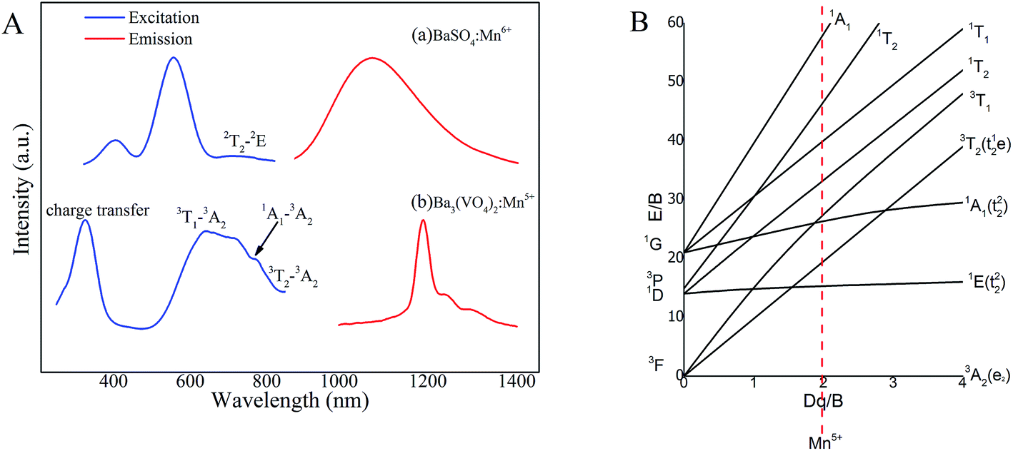 | ||
| Fig. 4 (A) Photoluminescence excitation and photoluminescence spectra of (a) BaSO4:Mn6+ and (b) Ba3(VO4)2:Mn5+; (B) Tanabe–Sugano energy diagram of a 3d2 system in a tetrahedral crystal field of Mn5+. a.u., arbitrary units. | ||
The energy levels of Ba3(VO4)2:Mn5+ can be expressed by a Tanabe–Sugano energy level diagram of a 3d2 system in tetrahedral crystal field, as shown in Fig. 4B. According to crystal field theory, the energy level sequence of Mn5+ ion in tetrahedral environment should be 3A2 < 1E < 1A1 < 3T2.16,21 The 1E → 3A2 transition of Mn5+ ions is not sensitive to local coordination because in a strong field situation, the ground state is a spin triplet 3A2 level and the 1E level is below the 3T2 level, becoming the first excited state. Based on the Tanabe–Sugano energy level diagram, the photoluminescence process can be described as follows. Firstly, the ground-state electrons of Mn5+ ions are promoted to the 3T1, 1A1 or 3T2 level after appropriate light excitation. Then, the excited electrons will relax to the lower 1E level, giving rise to a longer-lived NIR emission due to 1E → 3A2 transition.
Fig. 5 exhibits the luminescence decay curves of Ba3(VO4)2:Mn5+ excited at 808 nm and monitored at 1190 nm. The red curve is a fit of the experimental data to a single exponential decay equation. The concentration dependence of the fluorescence lifetime of Ba3(VO4)2:Mn5+ phosphors is given in the inset. It is found that the decay lifetime is well fitted by a first-order exponential equation:
I(t) = I0 + A![[thin space (1/6-em)]](https://www.rsc.org/images/entities/char_2009.gif) exp(−t/τ) exp(−t/τ)
| (1) |
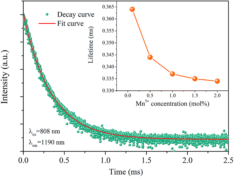 | ||
| Fig. 5 Decay curve of Ba3(VO4)2:Mn5+ phosphor. The red curve is a fit of the experimental data to a single exponential decay equation. Inset: the concentration dependence of fluorescence lifetime of Ba3(VO4)2:x mol% Mn5+ phosphor (x = 0.1, 0.5, 1, 1.5, 2). a.u., arbitrary units. | ||
Fig. 6A presents SEM images of Ba3(VO4)2:Mn5+ nanoparticles before and after anion exchange reaction. The Ba3(VO4)2:Mn5+ nanoparticles exhibit flake-like micromorphology with a particle size in the range 150–450 nm. The shape and size of particles remain unchanged after anion exchange reaction at low doping concentration. Fig. 6B shows the particle size distribution of Ba3(VO4)2:1 mol% Mn5+ nanoparticles, measured by DLS. The mean particle diameter is 295 nm, which corresponds to that in the SEM images. In order to further confirm Mn5+ was successfully doped into the Ba3(VO4)2 nanoparticles, we carried out elemental mapping measurements and elemental line scanning. Fig. 7a–c shows the EDX mapping of Ba3(VO4)2:x mol% Mn5+ with different doping concentrations (x = 0.5, 1, 1.5). The white color represents the digital TEM image of Ba3(VO4)2 nanoparticles. The green, blue and red colors represent V, Mn and Ba elements, respectively. As we can see, Mn5+ is distributed uniformly across the nanoparticles. With increasing Mn5+ doping concentration, the signal intensity of Mn element becomes higher. A similar result was also obtained in the EDX line scanning of Ba3(VO4)2:Mn5+, as shown in Fig. 8. The EDX analysis reveals that the elemental composition of the nanoparticles is Ba, V, O, and Mn. The signal intensity of Mn element distributed at the edges of particles is much lower than that in the center, indicating that the majority of Mn5+ ions are distributed on the surface of the nanoparticles. The results demonstrate that Mn5+ ions are successfully doped into the Ba3(VO4)2 nanoparticles by the chemical transform approach.
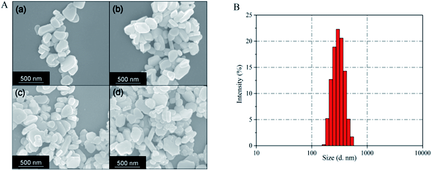 | ||
| Fig. 6 (A) SEM image of Ba3(VO4)2:x mol% Mn5+ nanoparticles: (a) x = 0, (b) x = 0.5, (c) x = 1, (d) x = 2. (B) Particle size distribution of Ba3(VO4)2:1 mol% Mn5+ nanoparticles, as measured by DLS. | ||
 | ||
| Fig. 7 EDX mapping of Ba3(VO4)2:x mol% Mn5+ with different doping concentrations: (a) x = 0.5, (b) x = 1, (c) x = 1.5. DF, dark field image. | ||
 | ||
| Fig. 8 EDX line scanning of Ba3(VO4)2:Mn5+, green, blue and red colors represent V, Ba and Mn elements, respectively. a.u., arbitrary units. | ||
In consideration of the similar valence and effective ionic radius, Mn5+ ions prefer to occupy the V5+ sites in the host. The overall chemical reaction of Ba3(VO4)2:Mn5+ can be represented by the following equation:
| xMnO43− + Ba3(VO4)2 → Ba3(V1−xMnxO4)2 + (1 − x)VO43− | (2) |
Generally, the diffusion rate in ion exchange reaction is an important factor to control the formation of the particles.22 In bulk materials, the diffusion rates of exchanged ions are quite low owing to the larger particle size. When it comes to nanosized materials, it has been reported that the diffusion rates are millions of times faster than in the bulk materials.23 However, anions have larger ionic radius than cations, so that the anion exchange reaction usually has a lower diffusion rate, which always makes rigorous reaction conditions necessary. It is acknowledged that the faster diffusion of cations than incoming anions based on the nanoscale Kirkendall effect is the main mechanism to explain the reaction of anion exchange.24 The nanoscale reduces the reaction barrier of nucleation so that Ba2+ are inclined to diffuse outward to the surface of particles and meet with the incoming MnO43− ions, leading to the precipitation of Mn5+ doped Ba3(VO4)2 nanoparticles. The doping concentration of incoming MnO43− ions is too low to change the rigid framework of VO43− anionic groups. Hence, the initial shape and size of particles is unchanged after reaction.
NIR emission charge-coupled device (CCD) images of the Ba3(VO4)2:x mol% Mn5+ nanoparticles with doping concentrations at x = 0.5, 1, 1.5 are given in Fig. 9a–c; these images were obtained by using an AsGaIn camera in a dark room. An 808 nm continuous-wave (CW) laser was used as the excitation source, in combination with a long pass optical filter with a 1000 nm cut-off wavelength. It was clearly observed that the Ba3(VO4)2:Mn5+ emits intense NIR-I to NIR-II light, indicating the nanoparticles can be effectively excited by an 808 nm laser. To further demonstrate whether the intensity of emission from the Ba3(VO4)2:Mn5+ is high enough for fluorescence imaging, we have obtained tissue images by injecting the nanoparticles into pork tissue at a depth of 5 mm. Fig. 9d and e show, respectively, optical and fluorescence images of Ba3(VO4)2:1 mol% Mn5+ nanoparticles in pork tissue under 808 nm laser light. As shown in Fig. 9e, clear high-contrast NIR luminescence with no auto-fluorescence can be detected with an excitation power density of approximately 500 mW cm−2, suggesting that the novel Mn5+ doped nanoparticles are potentially an ideal fluorescent probe in the NIR-II biological window.
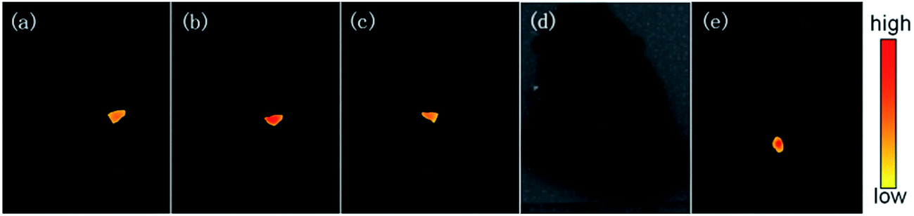 | ||
| Fig. 9 NIR emission CCD pictures of the Ba3(VO4)2:x mol% Mn5+ nanoparticles with doping concentration at (a) x = 0.5, (b) x = 1, (c) x = 1.5. (d) Optical and (e) fluorescence images of Ba3(VO4)2:1 mol% Mn5+ nanoparticles in pork tissue, excited by 808 nm laser. | ||
4. Conclusions
In conclusion, we provide, for the first time, we believe, a facile two-step strategy based on efficient anion exchange reaction to fabricate Mn5+ doped nanoparticles. This novel approach not only can stabilize the valence, but also is able to control the uniform size. The Mn5+ doped Ba3(MO4)2 (M = V, P) nanoparticles exhibit a remarkable NIR-II emission around 1190 nm with a broad excitation band in the visible and NIR region, which indicates Mn5+ doping has potential application in advanced NIR-II fluorescence imaging. By our approach, other candidate hosts for Mn5+ ions, consisting of Ca3(VO4)2, Sr3(VO4)2 and Ba2SiO4, can also be fabricated. To sum up, the general strategy illustrated in this paper will likely stimulate new ideas to prepare special valence ion doped nanosized materials.Acknowledgements
This work was financially supported by the National Natural Science Foundation of China (Grants no. 51472091), Guangdong Natural Science Foundation (Grants no. S2011030001349).References
- R. Wang and F. Zhang, J. Mater. Chem. B, 2014, 2, 2422–2443 RSC.
- M. Chen and M. Yin, Prog. Polym. Sci., 2013, 39, 365–395 CrossRef.
- A. M. Smith, M. C. Mancini and S. Nie, Nat. Nanotechnol., 2009, 4, 710–711 CrossRef CAS PubMed.
- V. J. Pansare, S. Hejazi, W. J. Faenza and R. K. Prud'Homme, Chem. Mater., 2012, 24, 812–827 CrossRef CAS PubMed.
- W. W. Yu, Y. A. W. And and X. Peng, Chem. Mater., 2003, 15, 4300–4308 CrossRef CAS.
- J. Chen, C. Guo, M. Wang, L. Huang, L. Wang, C. Mi, J. Li, X. Fang, C. Mao and S. Xu, J. Mater. Chem., 2011, 21, 2632–2638 RSC.
- G. Hong, J. T. Robinson, Y. Zhang, S. Diao, A. L. Antaris, Q. Wang and H. Dai, Angew. Chem., 2012, 51, 9818–9821 CrossRef CAS PubMed.
- J. T. Robinson, G. Hong, Y. Liang, B. Zhang, O. K. Yaghi and H. Dai, J. Am. Chem. Soc., 2012, 134, 10664–10669 CrossRef CAS PubMed.
- Y. Zhang, G. Hong, Y. Zhang, G. Chen, F. Li, H. Dai and Q. Wang, ACS Nano, 2012, 6, 3695–3702 CrossRef CAS PubMed.
- J. T. Robinson, K. Welsher, S. M. Tabakman, S. P. Sherlock, H. Wang, R. Luong and H. Dai, Nano Res., 2010, 3, 779–793 CrossRef CAS PubMed.
- U. Rocha, K. U. Kumar, C. Jacinto, I. Villa, F. Sanz-Rodríguez, A. Juarranz, E. Carrasco, F. C. J. M. V. Veggel and E. Bovero, Small, 2014, 10, 1141–1154 CrossRef CAS PubMed.
- Y. T. Lim, S. Kim, A. Nakayama, N. E. Stott, M. G. Bawendi and J. V. Frangioni, Mol. Imaging, 2003, 2, 50–64 CrossRef CAS PubMed.
- U. Oetliker, M. Herren, H. U. Güdel, U. Kesper, C. Albrecht and D. Reinen, J. Chem. Phys., 1994, 100, 8656–8665 CrossRef CAS.
- L. D. Merkle, A. Pinto, H. R. Verdún and B. Mcintosh, Appl. Phys. Lett., 1992, 61, 2386–2388 CrossRef CAS.
- M. F. Hazenkamp, H. U. Güdel, S. Kück, G. Huber, W. Rauw and D. Reinen, Chem. Phys. Lett., 1997, 265, 264–270 CrossRef CAS.
- R. Moncorgé, H. Manaa and G. Boulon, Opt. Mater., 1994, 4, 139–151 CrossRef.
- T. C. Brunold, M. F. Hazenkamp and H. U. Guedel, J. Am. Chem. Soc., 2002, 117, 5598–5599 CrossRef.
- R. Cao, J. Qiu, X. Yu and X. Sun, ECS J. Solid State Sci. Technol., 2013, 2, R237–R240 CrossRef CAS.
- L. C. Ferracin, M. R. Davolos and L. A. O. Nunes, J. Lumin., 1997, 72–74, 185–187 CrossRef CAS.
- M. Herren, T. Riedener, H. U. Güdel, C. Albrecht, U. Kaschuba and D. Reinen, J. Lumin., 1992, 53, 452–456 CrossRef CAS.
- J. A. Capobianco, G. Cormier, M. Bettinelli, R. Moncorgé and H. Manaa, J. Lumin., 1992, 54, 325 CrossRef.
- R. D. Robinson, B. Sadtler, D. O. Demchenko, C. K. Erdonmez, L. W. Wang and A. P. Alivisatos, Science, 2007, 317, 355–358 CrossRef CAS PubMed.
- C. Dong and F. C. J. M. V. Veggel, ACS Nano, 2009, 3, 123–130 CrossRef CAS PubMed.
- J. Park, H. Zheng, Y. W. Jun and A. P. Alivisatos, J. Am. Chem. Soc., 2009, 131, 13943–13945 CrossRef CAS PubMed.
| This journal is © The Royal Society of Chemistry 2017 |