
 Open Access Article
 This Open Access Article is licensed under a
 Creative Commons Attribution 3.0 Unported Licence
Enhanced capacity and cycle life of nitrogen-doped activated charcoal anode for the lithium ion battery: a solvent-free approach†
Chandrasekar M. Subramaniyam ab,
N. R. Srinivasanc,
Zhixin Taia,
Hua Kun Liu*a and
Shi Xue Doua
ab,
N. R. Srinivasanc,
Zhixin Taia,
Hua Kun Liu*a and
Shi Xue Doua
aInstitute for Superconducting and Electronic Materials, Australian Institute for Innovative Materials, University of Wollongong, Innovation Campus, North Wollongong, NSW 2500, Australia. E-mail: hua@uow.edu.au
bTexas Materials Institute, Department of Mechanical Engineering, University of Texas Austin, 204 E Dean Keeton St., C2200, Austin, Texas 78712, USA
cDepartment of Chemical Engineering, Indian Institute of Technology Madras, Chennai 600036, India
First published on 15th March 2017
Abstract
Herein, we investigated the electrochemical performance of nitrogen-doped commercial activated charcoal (R-AC) for lithium-ion batteries (LIBs). With this aim, nitrogen was doped into R-AC via a solvent-free approach, which involved annealing R-AC under N2 and NH3 atmospheres at 800 °C, and the product was tested as an anode for LIBs. The sample annealed under an NH3 atmosphere (NH-AC) had a nitrogen doping level of 4.7 at% with a specific surface area of 894.5 m2 g−1 and a reduced O/C ratio of 0.31 in comparison to the sample annealed under an N2 atmosphere (N-AC) and R-AC. Raman spectroscopy detected disorder/defects owing to the introduction of various C–N–C terminal bonds on the surface of R-AC, which significantly improved the electrical conductivity of both N-AC and NH-AC. Therefore, endowed with these physicochemical properties, NH-AC delivered a high specific capacity of 736.4 mA h g−1 at 50 mA g−1 (up to 150 cycles) and 524 mA h g−1 at 200 mA g−1 even after 500 cycles, which indicates much better performance in comparison to those of R-AC, N-AC and commercial graphite. This remarkable electrochemical performance of NH-AC can be attributed to the synergistic effect of its large specific surface area, disordered graphitic structure, and low charge transfer resistance, which enable it to act as an anode for high-performance LIBs.
Introduction
In recent years, the market for electrochemical storage devices has rapidly increased to reduce our dependence on fossil fuels, which are needed to operate most transportation systems. Among all energy storage devices, the lithium-ion battery (LIB) is the most promising owing to its high gravimetric energy density, high power density, and low self-discharge rate. Ever since its commercialization by Sony Inc. In the 1990s, it has revolutionized the market for portable electronic devices and is therefore considered to be the most likely eco-friendly candidate for powering electric vehicles (EV)/plug-in EVs and providing off-grid energy storage to eliminate power transmission losses.1–3 In commercial lithium-ion batteries (LIBs), graphite is used as the anode and is still preferred in spite of the enormous progress made in high-energy alloying and conversion-based materials.4,5 This is mainly due to the numerous merits of graphite, despite its demerits, such as low reversible specific capacity and rate performance, which limit the use of present state-of-the-art electrodes for large-scale energy storage applications.6,7 Therefore, carbon-based anode materials that exhibit excellent reversible specific capacity and cycling performance are required for the abovementioned applications.The mechanism of intercalation and deintercalation of lithium with carbonaceous materials could be expressed as 6C + yLi+ + xe− = LiyC6, in which y is the stoichiometric factor, where y = 1 for graphitic carbon and 0.5 < y < 3 for low-temperature-annealed non-graphitic carbon.8 Although the latter displays a high specific capacity, it also suffers from large irreversible capacity losses in the first cycle owing to decomposition of the electrolyte and the formation of a solid-electrolyte interphase (SEI) over its surface at an operating voltage close to that of lithium. It traps a large amount of lithium ions in its network during intercalation owing to oxygen-containing surface functional groups or diffusion constraints.9 Even so, the initially formed SEI layer prevents further decomposition of the electrolyte at the anode surface and reduces the diffusivity of charge carriers between the anode and the electrolyte. Therefore, the thickness of the SEI layer could be adjusted by tailoring the properties of carbon and the surface functional groups. Numerous strategies are used to mitigate the formation of an SEI by tuning its morphology, such as the use of graphene, carbon nanotubes, carbon nanofibers, and porous carbon.10 Nanostructured porous carbons are of great interest as they provide enhanced reversible lithium storage and excellent cycling life. This is achieved because of their large electrode–electrolyte interface, which promotes the charge transfer reaction by reducing the diffusion length of lithium. Another approach comprises the modification of their surface functional groups with non-carbon elements such as nitrogen, sulphur, and phosphorus.11,12 The presence of heteroatoms enhances the reactivity and electrical conductivity and thereby increases the lithium storage capacity.13 In addition to these advantages, amorphous carbon also displays high mechanical stability against the volumetric changes that occur during the insertion and deinsertion of lithium. Hence, surface-modified nanostructured carbon provides an excellent network for interstitial connections, which results in superior electrochemical performance, and also acts as a buffering agent for mechanically weak inorganic electrode materials.9
Because commercial activated charcoal (R-AC) possesses a large specific surface area (>500 m2 g−1) and pore volume (0.8 cm3 g−1), it is widely used in supercapacitors and also finds applications in the areas of hydrogen storage, water treatment, and separation techniques.10,14 As mentioned earlier, the introduction of nitrogen heteroatoms into carbon leads to the modification of its surface with functional groups, which further enhances its electrochemical performance with respect to Li+/Li0. Multiple ways of introducing N atoms have been investigated in recent years10 using nitric acid and melamine as N sources. These chemical precursors tend to give rise to a low nitrogen percentage with morphological changes and also leave unreacted chemicals/inactive species in the product, which impede its electrochemical performance. With this aim, a solvent-free inexpensive method has been chosen in this study for doping heteroatoms into commercial activated carbon (AC) to understand the behaviour of the electrode during the cycling process in LIBs. The selection of R-AC as the anode was based on its commercial availability at a low cost in comparison to that of conventional graphite.
Results and discussion
The XRD patterns of R-AC, N-AC, and NH-AC are shown in Fig. 1a. Distinct peaks are observed together with broad peaks in the 2θ ranges of 20–25° and 42–45°, which could be due to the reflections of the (002) and (100) planes, respectively.15 In addition, there was a slight shift of 0.15° in 2θ towards higher angles and the peaks were broadened as a result of annealing under N2 and NH3 gases, which confirms the presence of amorphous carbon. More importantly, the shift in 2θ values could be due to an increase in the interlayer spacing between the (002) planes of graphite in terms of Bragg's equation. Moreover, the degree of graphitization of all the samples was found to be 1.98 ± 0.03, which was measured using an empirical parameter (R) and indicates that treatment with N2 or NH3 gas did not significantly alter the graphitic structure. The parameter R is defined as the ratio of the height of the (002) Bragg peak to its background.16 The value of R for soft carbon is 1.5, which is lower than that for hard carbon samples. The high value of R indicates the presence of a well-developed (highly crystalline) graphitic structure. Furthermore, it can be seen that there are very small sharp peaks in the XRD patterns, which may be due to SiO2. These SiO2 peaks would have originated from the sources that were used for the preparation of activated charcoal. The SiO2 commonly used sources of activated charcoal are coal, wood, and coconut shell. For example, coconut shell is an agricultural product, and its major and minor constituents are cellulose, lignin, pentosans, and silica, respectively. Therefore, commercial activated charcoal contains 12 wt% non-carbonaceous materials (including silica), as deduced from thermogravimetric analysis (TGA, Fig. S1†), which result in a peak in the XRD pattern.17 To investigate the disordered structure of R-AC, Raman spectroscopy is widely used to determine the structural disorder that exists in carbonaceous materials. The Raman spectra in Fig. 1b display two prominent peaks at 1330 cm−1 and 1602 cm−1, which correspond to the D band (sp3 carbon related to structural defects) and the G band (sp2 carbon, which is the fingerprint of graphitic crystallites of carbon), respectively. The intensity ratio of these bands (ID/IG) depends on the ratio of the concentrations of sp3 and sp2 carbons, which is related to the degree of graphitization and can be used to analyse defective structures produced by different contents of various C–N–C terminal bonds.18,19 In particular, the ID/IG ratio for NH-AC is 1.39, which is higher than those for R-AC (1.30) and N-AC (1.29). It is evident that disordered and defective sites are predominant in the carbon matrix of NH-AC owing to the introduction of heteroatoms during heat treatment under ammonia atmosphere. This is in good agreement with the conclusions drawn from the XRD pattern of NH-AC. The larger electrolyte/electrode interfacial area will provide better wettability, as well as easy access to storage sites. Brunauer–Emmett–Teller (BET) measurements were conducted to determine the specific surface areas of all the samples. From the BET analysis, the measured specific surface areas were found to be 557, 681.8, and 894.5 m2 g−1 for R-AC, N-AC, and NH-AC, respectively, as shown in Fig. 1c. The increase in surface area for NH-AC was probably due to the removal of carbon from the surface by treatment with ammonia gas, which led to the formation of numerous micropores.20 This is clearly reflected in both the BET measurements and observations by field-emission scanning electron microscopy (FESEM) (Fig. 2).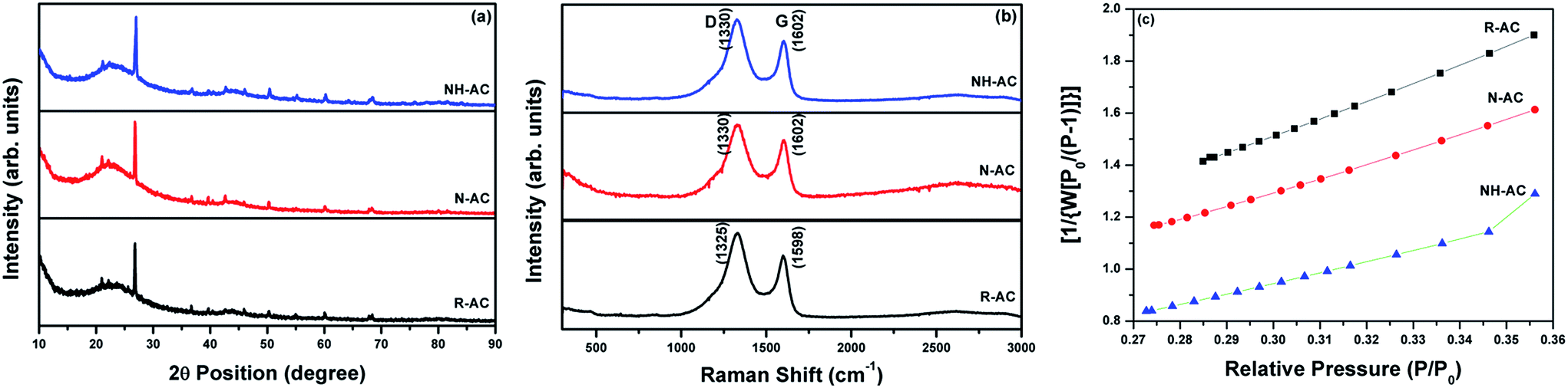 | ||
| Fig. 1 (a) X-ray diffraction patterns, (b) Raman spectra and (c) surface area plots of unannealed activated carbon (R-AC) and activated carbon annealed under an N2 atmosphere (N-AC) and annealed under an NH3 atmosphere (NH-AC). | ||
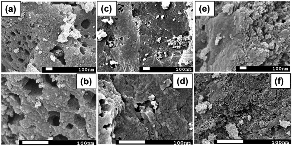 | ||
| Fig. 2 Morphology of (a and b) raw activated charcoal (R-AC); (c and d) R-AC annealed under an N2 atmosphere (N-AC); (e and f) R-AC annealed under NH3 atmosphere (NH-AC). | ||
Morphological investigations using scanning electron microscopy (SEM) were carried out for all samples (R-AC, N-AC, and NH-AC), and the SEM images are presented in Fig. 2. Fig. 2a and b show that R-AC contains numerous macropores. On annealing R-AC under a nitrogen atmosphere for the preparation of N-AC (Fig. 2c and d), the nitrogen reacted with the surface of the carbon and removed oxygen in the form of CO and CO2 gases. The evolution of these gases will probably have created more pores, leading to a larger specific surface area. It is believed that the reaction between a carbon surface and gas molecules (NH3) can lead to the substantial removal of carbon in the form of CH4. As a result, NH-AC (Fig. 2e and f) exhibits a larger specific surface area than that of N-AC and R-AC.20,21 It is evident from these SEM images that the porous structure was retained in all samples, even after annealing at 800 °C.
X-ray photoelectron spectroscopy (XPS) analysis was performed to determine the elemental compositions and chemical states of the samples. The complete survey spectra of R-AC, N-AC, and NH-AC (not shown here) indicate that C and O elements are the major components, of which the peaks are centred at 284 and 532 eV, respectively, whereas the minor elements are N and Si. The elemental surface compositions of the samples are summarized in Table 1. It is observed from Table 1 that the nitrogen content increased with a decrease in the oxygen content when R-AC was annealed under both nitrogen and ammonia atmospheres. Moreover, from the O/C ratio it is clear that the amount of polar functional groups was also drastically reduced during the heat treatment of R-AC. These polar functional groups were responsible for the formation of a thick and irregular SEI film on the surfaces of carbon particles. The high-resolution C 1s spectra of all the samples can be deconvolved into four peaks, as shown in Fig. 3a, c, and e. The peaks around 284.6, 285.5, 287, and 289.2 eV can be assigned to C![[double bond, length as m-dash]](https://www.rsc.org/images/entities/char_e001.gif) C, C–N and C–C, CO, and OC–OH, respectively. Similarly, the high-resolution N 1s spectra can be deconvolved into 4 peaks (Fig. 3b, d, and f); these are centred at 398.6, 400.1, 401.6, and 403.4 eV, which could be assigned to pyridinic N, pyrrolic N, graphitic N, and oxidized N, respectively.18,22–24 The doped nitrogen contents were found to be 2.6, 3.2, and 4.7 at% for R-AC, N-AC, and NH-AC, respectively. From the point of view of electrochemical performance, a nitrogen-doped carbon matrix (in particular with pyridinic N and pyrrolic N) could generate more active sites for lithium-ion storage, as well as electron transport. A possible reason for the enhancement in electrochemical performance is the faradic reaction of the nitrogen-containing functional groups.18,22–24 Furthermore, nitrogen doping also improved the wettability and conductivity of the carbon matrix. It is evident from Table 2 that the concentrations of pyridinic N and pyrrolic N are higher in NH-AC in comparison to those in R-AC and N-AC. The evolution of these functional groups in the NH-AC matrix increased the amount of pores, which is in good agreement with the BET analysis.
C, C–N and C–C, CO, and OC–OH, respectively. Similarly, the high-resolution N 1s spectra can be deconvolved into 4 peaks (Fig. 3b, d, and f); these are centred at 398.6, 400.1, 401.6, and 403.4 eV, which could be assigned to pyridinic N, pyrrolic N, graphitic N, and oxidized N, respectively.18,22–24 The doped nitrogen contents were found to be 2.6, 3.2, and 4.7 at% for R-AC, N-AC, and NH-AC, respectively. From the point of view of electrochemical performance, a nitrogen-doped carbon matrix (in particular with pyridinic N and pyrrolic N) could generate more active sites for lithium-ion storage, as well as electron transport. A possible reason for the enhancement in electrochemical performance is the faradic reaction of the nitrogen-containing functional groups.18,22–24 Furthermore, nitrogen doping also improved the wettability and conductivity of the carbon matrix. It is evident from Table 2 that the concentrations of pyridinic N and pyrrolic N are higher in NH-AC in comparison to those in R-AC and N-AC. The evolution of these functional groups in the NH-AC matrix increased the amount of pores, which is in good agreement with the BET analysis.
| Sample ID | Elemental composition (at%) | O/C ratio | |||
|---|---|---|---|---|---|
| C 1s | N 1s | O 1s | Si 2p | ||
| R-AC | 64.3 | 2.6 | 32.5 | 0.6 | 0.51 |
| N-AC | 72.9 | 3.2 | 23.3 | 0.6 | 0.32 |
| NH-AC | 72.5 | 4.7 | 22.2 | 0.6 | 0.31 |
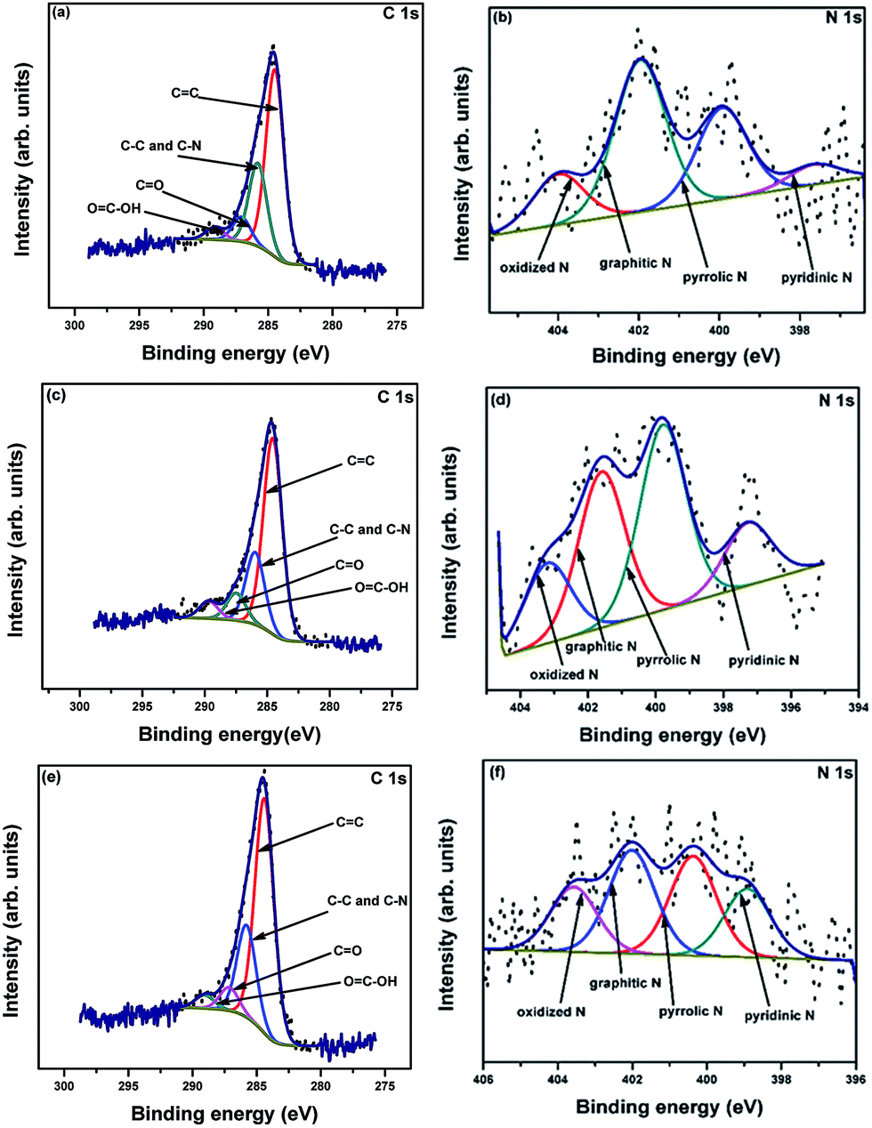 | ||
| Fig. 3 XPS high-resolution C 1s and N 1s spectra of R-AC (a and b), N-AC (c and d), and NH-AC (e and f). | ||
| Sample ID | Composition (at%) | |||
|---|---|---|---|---|
| Pyridinic N 398.2 eV | Pyrrolic N 400.1 eV | Graphitic N 401.6 eV | Oxidized N 403.4 eV | |
| R-AC | 0.2 | 0.8 | 1.3 | 0.4 |
| N-AC | 0.4 | 1.2 | 1.0 | 0.5 |
| NH-AC | 1.0 | 1.4 | 1.4 | 0.9 |
To acquire insights into the effects of N doping, commercial graphite, R-AC, N-AC, and NH-AC were tested as anodes at a moderate current rate of 50 mA g−1. The initial specific discharge and charge capacities were found to be 402.3 and 284.1 mA h g−1 (graphite); 984.6 and 353.6 mA h g−1 (R-AC); 1165.3 and 482.9 mA h g−1 (N-AC), and 2376.1 and 1092.6 mA h g−1 (NH-AC), respectively. The initial coulombic efficiency was greatly increased for NH-AC (45.98%) in comparison that of to N-AC (41.44%) and R-AC (35.91%). This irreversible loss could be attributed to the irreversible formation of Li2O and the solid-electrolyte interphase (SEI), which retains lithium ions, and the decomposition of the electrolyte at lower voltages, as confirmed by CV (Fig. 4a, inset). This is in good agreement with other reports that refer to carbonaceous materials.8,10,13,16,21,25 Nevertheless, all the electrodes exhibited a coulombic efficiency of 98–99% from the second cycle onwards. The NH-AC electrode delivered the highest reversible specific capacity of 736.4 mA h g−1 in comparison to N-AC (464.9 mA h g−1) and R-AC (459.9 mA h g−1) when the electrodes were cycled at a current rate of 50 mA g−1, even after 150 cycles, which indicates superior performance to that of commercial graphite (259.1 mA h g−1), as shown in Fig. 4b and S2.†
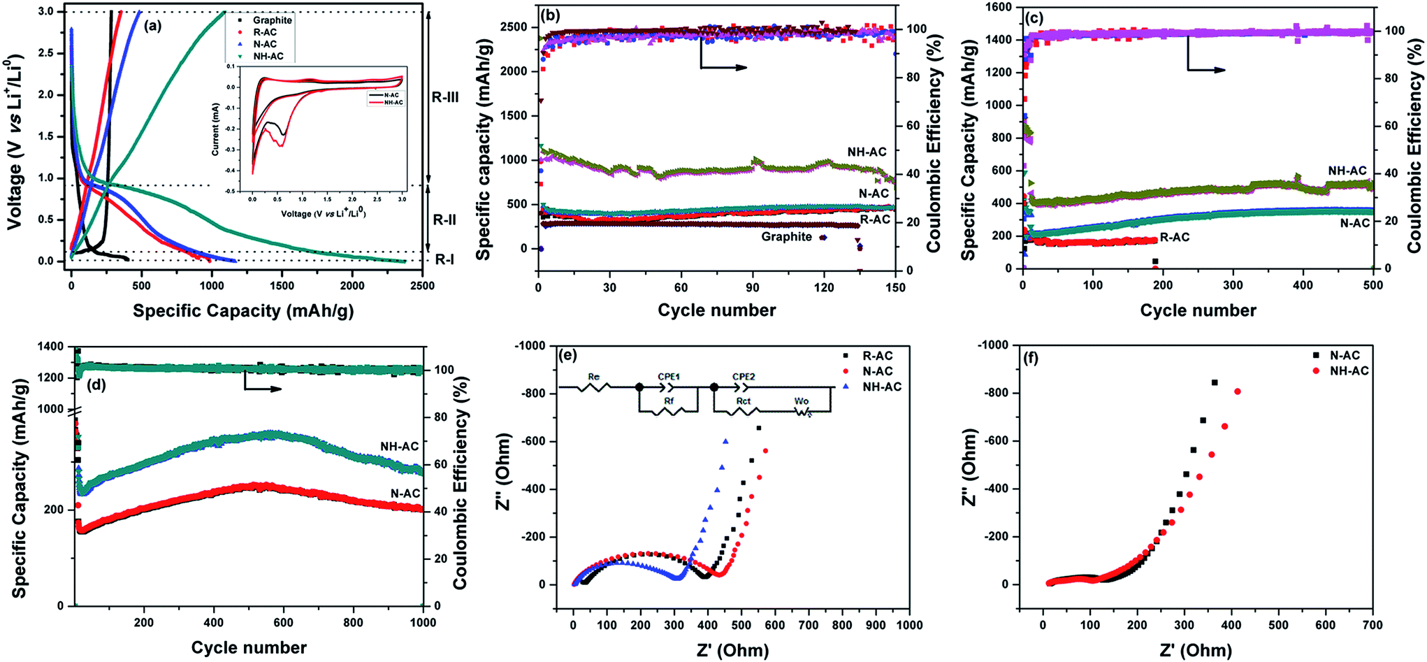 | ||
| Fig. 4 Electrochemical performance of R-AC, N-AC, and NH-AC: (a) first discharge–charge plots at 50 mA g−1 (with inset containing cyclic voltammograms of N-AC and NH-AC obtained at a scan rate of 0.1 mV s−1 for 3 cycles each); specific capacity plots at (b) 50 mA g−1, (c) 200 mA g−1, and (d) 500 mA g−1; and impedance spectra and equivalent circuit (inset) of N-AC and NH-AC electrodes (e) before cycling and (f) after 1000 cycles. | ||
The voltage–specific discharge capacity profile can be divided into three regions (R-I, R-II, and R-III) according to the intercalation of Li+ in different regions of carbon.26–28 Region R-I (0.002–0.1 V) can be mainly assigned to the intercalation of Li+ ions into the interplanar spaces between aligned graphene sheets. In the case of region R-II (0.1–0.9 V), the contribution to the specific capacity can be ascribed to the intercalation of Li+ between disordered and ordered graphene sheets. In the voltage range above 0.9 V (R-III), the contribution to the capacity can be attributed to the intercalation of Li+ into edge sites, in particular surface functional groups. Table 3 shows the contributions to the specific capacity for all regions of the profile.
| Region | Specific capacity (mA h g−1) | |||
|---|---|---|---|---|
| Graphite | R-AC | N-AC | NH-AC | |
| R-I (0.02–0.1 V) | 216.1 | 148.4 | 257.5 | 563.5 |
| R-II (0.1–0.9 V) | 139.7 | 706.4 | 726.4 | 1435.5 |
| R-III (above 0.9 V) | 46.5 | 129.8 | 181.4 | 377.1 |
| Total specific capacity (mA h g−1) | 402.3 | 984.6 | 1165.3 | 2376.1 |
As can be seen, in the case of graphite the contribution to the specific capacity mainly originates from the graphene sheets. NH-AC possesses higher specific capacity in the R-I region, which could be related to the number of available graphene sheets per unit area as well as the interplanar spacing between the graphene sheets, as confirmed by XRD. Furthermore, the increased specific capacity of NH-AC in the other regions (R-II and R-III) may be related to the disordered structure and surface functional groups, as confirmed by other characterization techniques such as XPS and Raman spectroscopy. Therefore, the contribution of the first cycle to the specific discharge capacity is correlated with the findings obtained from characterization techniques.
To test their long-term cycling stability at high current rates, NH-AC and N-AC were subjected to electrochemical performance testing at 200 mA g−1 for 500 cycles (Fig. 4c) and 500 mA g−1 for 1000 cycles (Fig. 4d) and rate capability testing at various current rates (Fig. S3†). NH-AC delivered high reversible capacities of 523.9 mA h g−1 and 281.1 mA h g−1 at current rates of 200 and 500 mA g−1 after 500 and 1000 cycles, respectively, whereas the N-AC electrode exhibited capacities of only 201.1 and 353 mA h g−1 at the same respective current rates and cycle numbers. It is believed that the intercalation of Li+ into graphene sheets contributed to the discharge capacity when the potential was below 0.11 V. Furthermore, the contribution of defects and surface functional groups to the capacity appeared above 0.1 V.29 Therefore, carbon with a large surface area and a disordered graphite structure is preferred for accommodating a large quantity of lithium ions. Moreover, the specific surface area is beneficial for the adsorption of lithium ions at interfacial sites and reducing the overpotential (small charge transfer resistance) owing to a decrease in the local current density.
Fig. 4e shows the electrochemical impedance spectra of these electrodes, which provide further insights into their remarkable electrochemical performance. The Nyquist plots consist of a semicircle at high frequencies and a straight line at low frequencies, which are attributed to the electrolyte or solution resistance (Re) offered at the electrode–electrolyte interface and the charge transfer resistance (Rct) in the case of the semicircle and the Warburg diffusion (Wo) of lithium in the case of the straight line, together with a constant-phase element (CPE-1) and a non-ideal constant-phase element (CPE-2), as represented in the equivalent circuit model. N-AC and NH-AC displayed a negligible electrolyte resistance of 2.43 Ω in comparison to 34.74 Ω for R-AC, whereas NH-AC exhibited an initial Rct value of 306.85 Ω in comparison to 431.52 Ω for N-AC and 393.8 Ω for R-AC. Therefore, the remarkable enhancement in Li storage for NH-AC can be considered to be due to (1) the high at% N content in the form of pyridinic N and pyrrolic N, which increased the electronic conductivity and induced defects, creating new surface active sites that enhanced the reactivity of lithium; (2) the porous structure with a large surface area, which helped to accommodate the changes in volume during lithiation and delithiation; (3) the lowest solution/electrolyte resistance at the electrode–electrolyte interface, which could further reduce the build-up of the SEI during cycling; and finally (4) the reduced Rct value of NH-AC after 1000 cycles in comparison to that before cycling, which indicates that new sites were generated during cycling that promoted remarkably stable electrochemical performance, even after 1000 cycles at a high current rate of 500 mA g−1. The electrochemical performance of NH-AC was also compared with that of other reports in the literature, as shown in Table 4. This electrode's outstanding performance may be due to its increased nitrogen content18,30–34 and reduced O/C ratio16 and the solvent-free approach, which left no chemical residues to impede its electrochemical performance.16,18,19,24,33 Thus, owing to its unique porous structure and low cost, NH-AC is able to deliver excellent reversible specific capacity, high rate capability, and very good cycling stability, as well as shows great potential to be competitive with other next-generation anode materials for secondary rechargeable batteries.
| Synthesis method/morphology | Composition of carbonaceous materials (N, C, O) at% | Surface area (m2 g−1) after N doping | Potential (V vs. Li+/Li0) | Current rate (mA g−1) | Initial capacity (mA h g−1) | Capacity retention (mA h g−1)/(cycles) | Reference |
|---|---|---|---|---|---|---|---|
| N-Doped activated charcoal (N-AC) annealed in ammonia gas atmosphere at 800 °C for 8 h | N – 4.7 | 894.47 | 0.002–3 | 200 | 2080 | 523.5 (500) | Present work |
| C – 72.5 | |||||||
| O – 22.2 | 500 | 1327.9 | 281 (1000) | ||||
| N-Doped carbon produced by carbonization and activation of phenol-melamine- formaldehyde resin at 700 °C for 2 h under an N2 gas atmosphere | N – 7.24 | 674.28 | 0.001–3 | 100 | 917 | 251 (20) | 16 |
| C – 63.66 | |||||||
| O – 22.88 | |||||||
| H – 1.61 | |||||||
| N-Containing activated carbons prepared from polyaniline (PANI) by KOH activation | N – 3.72 | 2287 | 0.001–3 | 100 | 2201 | 747 (20) | 30 |
| C – 86.55 | |||||||
| O – 9.73 | |||||||
| N-Doped porous graphene material prepared by freeze-drying a graphene/melamine–formaldehyde hydrogel and subsequent annealing | N – 5.8 | 1170 | 0.005–3 | 400 | 458 | 496 (200) | 24 |
| Remainder | |||||||
| C and O | |||||||
| S- and N-dual-doped porous carbon produced by carbonizing the shells of broad beans by chemical activation | N – 2.2 | 655.4 | 0.01–3 | 372 | 845.2 | 261.5 (100) | 33 |
| S – 0.97 | |||||||
| Remainder C and O | |||||||
| N-Doped MWCNT synthesized by an aerosol-assisted catalytic CVD technique using toluene and acetonitrile in various ratios | For 25% CH3CN | — | 0.01–2.5 | 0.26 mA cm−2 | 568.3 | 270 (30) | 35 |
| N – 1.23 | |||||||
| Remainder C and O | |||||||
| N-Doped hierarchical porous carbon derived from fish scales | N – 3.95 | 1980 | 0.01–2.5 | 75 | 1521.2 | 509.7 (75) | 36 |
| C – 84.53 | |||||||
| O – 11.52 | |||||||
| N-Doped chitosan-based carbon cryogel synthesized via a combined process of freeze-drying and high-temperature carbonization | N – 3.14 | 1025 | 0–3 | 100 | 1148 | 395 (100) | 34 |
| O – 14.97 | |||||||
| Remainder C | |||||||
| N-Doped carbon xerogels obtained from melamine–resorcinol–formaldehyde precursors | N – 1.8 | 2912 | 0.01–3 | 37.2 | ∼1450 | 645 (50) | 18 |
| Remainder C and O | |||||||
| N-Doped porous carbon obtained from garlic peel as high-capacity anode | N – 4.12 | 1710 | 0.01–2.5 | 100 | 570 | 540 | 31 |
| C – 86.39 | |||||||
| O – 9.39 | |||||||
| N-Doped amorphous carbon nanosheets synthesized by thermal decomposition of EDTA manganese disodium salt hydrate | N – 9.8 | 242.3 | 0.02–2.5 | 250 | 1193.4 | 465.8 (600) | 19 |
| C – 77.87 | |||||||
| O – 12.96 | |||||||
| N-Rich hierarchical porous carbon monoliths produced via ice-templating | N – 16.4 | 173 | 0.005–3 | 50 | 745 | 560 (100) | 23 |
| C – 72 | |||||||
| O – 10.56 | |||||||
| H – 1.04 | |||||||
| N-Doped 3D free-standing porous graphene/graphite foam obtained by in situ activation | N – 2 to 3 | 943 | 0.01–3 | 186 | ∼550 | 397 (300) | 22 |
| Remainder C and O | |||||||
| N-Enriched ordered mesoporous carbons | N – 24.4 wt% | 251 | 0.01–3 | 100–300 | 1034 | 505 (300) | 25 |
| Remainder C and O | |||||||
| N-Doped graphene obtained using hexamethylenetetramine as a single source by a hydrothermal method | N – 1.68 | 466 | 0.01–3 | 100–200 | 1420 | 600 (50) | 32 |
| Remainder C and O | 500 (150) | ||||||
| N-Doped porous carbon microspheres produced under an ammonia atmosphere | N – 6.3 | 1630 | 0.005–3 | 50 | 816 | 660 (50) | 21 |
| C – 91.5 | |||||||
| O – 2.2 |
Conclusions
In this study, a solvent-free approach was selected for doping nitrogen into commercial activated charcoal (R-AC) to demonstrate its potential as an anode for LIBs. For nitrogen doping, R-AC was annealed under two different gases, namely, N2 (N-AC sample) and NH3 (NH-AC sample), and it was found for NH-AC that the nitrogen content increased to 4.7 at% in comparison to that of N-AC (3.2 at%) and R-AC (2.6 at%). Simultaneously, the specific surface area of NH-AC (894.5 m2 g−1) was increased together with a reduction in the O/C ratio in comparison to the other samples. Upon testing against lithium, NH-AC delivered remarkable specific capacities of 736.4 mA h g−1 after 150 cycles at 50 mA g−1, 524 mA h g−1 after 500 cycles at 200 mA g−1, and a stable 281 mA h g−1 at 500 mA g−1, even after 1000 cycles, with improved reversible coulombic efficiency in comparison to commercial activated charcoal and other types of porous carbon, as shown in Table 4. This excellent electrochemical performance was achieved due to a reduction in electrolyte resistance, which restricted the build-up of the SEI, and the introduction of various C–N–C terminal bonds at induced defects and new active sites, which enhanced the reactivity of lithium, and therefore NH-AC appears to be a promising candidate for high-performance lithium-ion batteries that require a high reversible specific capacity and remarkable cycling stability.Experimental
Materials synthesis
Activated charcoal powder (R-AC) (DARCO, 100 mesh, product no. 242276, lot no. MKBJ9846V, Sigma-Aldrich) was used as the starting material. A sample of 1 g R-AC powder was taken in an alumina vial and placed inside a tubular furnace, which was then purged with nitrogen gas (N2) for 1 h prior to the annealing process. The furnace temperature was maintained at 800 °C (ramped at 5 °C min−1) for 8 h and then cooled naturally to room temperature. The resulting product was denoted as N-AC. The abovementioned procedure under similar conditions was carried out with another sample of 1 g R-AC under an ammonia gas atmosphere, and the product was denoted as NH-AC. All samples were preserved in a vacuum desiccator spread with silica gel to eliminate moisture.Materials characterizations
Commercial raw activated charcoal (R-AC) and R-AC annealed in atmospheres of N2 (N-AC) and ammonia (NH-AC) gas were subjected to phase identification and surface and electrochemical characterization. X-ray diffraction (XRD, GBC MMA equipped with a Cu Kα radiation source) was employed for phase identification at a scan rate of 2° min−1 and a step size of 0.02°. Structural characterization of these materials was conducted by Raman spectroscopy using a Jobin Yvon Horiba Raman spectrometer (model HR800) with a 10 mW helium/neon laser at an excitation wavelength of 632.8 nm in the range of 150–2000 cm−1. X-ray photoelectron spectroscopy (XPS) was conducted using a SPECS Phoibos 100 analyser installed in a high-vacuum chamber with a base pressure of less than 10−8 mbar, and X-ray excitation was provided by an Al Kα irradiation source with photon energy hν of 1486.6 eV at a high voltage of 12 kV and a power of 120 W. XPS binding energy spectra were recorded at a pass energy of 20 eV in fixed analyser transmission mode, and data analysis was carried out using the CasaXPS 2.3.15 software package with all spectra calibrated against C 1s = 284.6 eV. Nitrogen adsorption–desorption studies were performed with a Quantachrome NOVA 1000 analyser for Brunauer–Emmett–Teller (BET) surface area analysis. Field-emission gun scanning electron microscopy (FEGSEM, JEOL JSM-7500F, Japan) was coupled with energy-dispersive X-ray spectroscopy (EDS) operated at 5 V and 10 μA to visualize and study the structural morphologies and compositions of the samples.Electrochemical characterizations
The electrochemical performance of the R-AC, N-AC, and NH-AC samples was studied using CR2032 coin cells in a half-cell configuration, which were assembled in an argon-filled glove box (MBraun, Germany). All samples were blended individually with polyvinylidene fluoride (Sigma-Aldrich) as a binder in a weight ratio of 9![[thin space (1/6-em)]](https://www.rsc.org/images/entities/char_2009.gif) :1, respectively, using N-methyl-2-pyrrolidone as a solvent. The slurry was mixed using a planetary mixer (Kurabo Mazerustar, Japan), and the slurry that was obtained was tape-cast over the copper current collector using the doctor blade technique and vacuum-dried at 120 °C overnight. The dried electrodes were cut into circular discs, with each electrode loaded with ∼1 mg cm−2 active materials. The half-cell-type coin cells were assembled using the as-prepared electrodes as the working electrode with Li metal foil as the counter/reference electrode separated by Celgard polypropylene film as the separator, which was impregnated with a few drops of commercially available 1 M LiPF6 in a 1:1 (v/v) mixture of ethylene carbonate (EC) and diethyl carbonate (DEC) as the electrolyte. All the assembled cells were electrochemically tested in a battery testing system (Land CT2001A, China) at a constant specific current rate (mA g−1) between 0.002 and 3.0 V. A Biologic VMP3 electrochemical workstation was employed to perform cyclic voltammetry (CV) at a scan rate of 0.1 mV s−1 and potentiostatic electrochemical impedance spectroscopy (PEIS) in the frequency range of 0.1 MHz to 10 mHz against Li+/Li0.
:1, respectively, using N-methyl-2-pyrrolidone as a solvent. The slurry was mixed using a planetary mixer (Kurabo Mazerustar, Japan), and the slurry that was obtained was tape-cast over the copper current collector using the doctor blade technique and vacuum-dried at 120 °C overnight. The dried electrodes were cut into circular discs, with each electrode loaded with ∼1 mg cm−2 active materials. The half-cell-type coin cells were assembled using the as-prepared electrodes as the working electrode with Li metal foil as the counter/reference electrode separated by Celgard polypropylene film as the separator, which was impregnated with a few drops of commercially available 1 M LiPF6 in a 1:1 (v/v) mixture of ethylene carbonate (EC) and diethyl carbonate (DEC) as the electrolyte. All the assembled cells were electrochemically tested in a battery testing system (Land CT2001A, China) at a constant specific current rate (mA g−1) between 0.002 and 3.0 V. A Biologic VMP3 electrochemical workstation was employed to perform cyclic voltammetry (CV) at a scan rate of 0.1 mV s−1 and potentiostatic electrochemical impedance spectroscopy (PEIS) in the frequency range of 0.1 MHz to 10 mHz against Li+/Li0.
Acknowledgements
The authors are grateful to the Commonwealth of Australia, Excellerate Australia, and the Automotive Australia 2020 Cooperative Research Centre (CRC) for financial support under project code AutoCRC 1-111, the Australian Research Council (ARC) for financial support through a Linkage Infrastructure Equipment and Facilities (LIEF) grant (No. LE0237478), with the facilities located at the UOW Electron Microscopy Centre, and the Institute for Superconducting and Electronic Materials (ISEM) for the use of its infrastructure as part of in-kind support. The authors would also like to thank Dr Tania Silver for critical review of the study. We also thank Yajie Liu and Dr Nasir Mahmood for Raman studies and technical discussions, respectively.References
- M. Armand and J. M. Tarascon, Nature, 2008, 451, 652–657 CrossRef CAS PubMed.
- J. B. Goodenough and Y. Kim, Chem. Mater., 2010, 22, 587–603 CrossRef CAS.
- B. Dunn, H. Kamath and J.-M. Tarascon, Science, 2011, 334, 928 CrossRef CAS PubMed.
- A. Magasinski, P. Dixon, B. Hertzberg, A. Kvit, J. Ayala and G. Yushin, Nat. Mater., 2010, 9, 353–358 CrossRef CAS PubMed.
- P. G. Bruce, B. Scrosati and J.-M. Tarascon, Angew. Chem., Int. Ed., 2008, 47, 2930–2946 CrossRef CAS PubMed.
- C. M. E. Peled, D. Bar-Tow and A. Melman, J. Electrochem. Soc., 1996, 143, 4 CrossRef.
- D. Aurbach, E. Zinigrad, Y. Cohen and H. Teller, Solid State Ionics, 2002, 148, 405–416 CrossRef CAS.
- R. A. Chunhui Chen, Y. Hao and C. Wang, ECS J. Solid State Sci. Technol., 2013, 2, 4 Search PubMed.
- E. Unur, S. Brutti, S. Panero and B. Scrosati, Microporous Mesoporous Mater., 2013, 174, 25–33 CrossRef CAS.
- K. Zhang, X. Li, J. Liang, Y. Zhu, L. Hu, Q. Cheng, C. Guo, N. Lin and Y. Qian, Electrochim. Acta, 2015, 155, 174–182 CrossRef CAS.
- W. Kiciński, M. Szala and M. Bystrzejewski, Carbon, 2014, 68, 1–32 CrossRef.
- J. P. Paraknowitsch and A. Thomas, Energy Environ. Sci., 2013, 6, 2839–2855 CAS.
- H.-g. Wang, Z. Wu, F.-l. Meng, D.-l. Ma, X.-l. Huang, L.-m. Wang and X.-b. Zhang, ChemSusChem, 2013, 6, 56–60 CrossRef PubMed.
- N. R. Srinivasan, P. A. Shankar and R. Bandyopadhyaya, Carbon, 2013, 57, 1–10 CrossRef CAS.
- A. Dandekar, R. T. K. Baker and M. A. Vannice, Carbon, 1998, 36, 1821–1831 CrossRef CAS.
- E. Liu, H. Shen, X. Xiang, Z. Huang, Y. Tian, Y. Wu, Z. Wu and H. Xie, Mater. Lett., 2012, 67, 390–393 CrossRef CAS.
- M. Sevilla and R. Mokaya, Energy Environ. Sci., 2014, 7, 1250–1280 CAS.
- X. Liu, S. Li, J. Mei, W.-M. Lau, R. Mi, Y. Li, H. Liu and L. Liu, J. Mater. Chem. A, 2014, 2, 14429–14438 CAS.
- W. Guo, X. Li, J. Xu, H. K. Liu, J. Ma and S. X. Dou, Electrochim. Acta, 2016, 188, 414–420 CrossRef CAS.
- K. Y. Kang, B. I. Lee and J. S. Lee, Carbon, 2009, 47, 1171–1180 CrossRef CAS.
- T. Chen, L. Pan, T. A. J. Loh, D. H. C. Chua, Y. Yao, Q. Chen, D. Li, W. Qin and Z. Sun, Dalton Trans., 2014, 43, 14931–14935 RSC.
- J. Ji, J. Liu, L. Lai, X. Zhao, Y. Zhen, J. Lin, Y. Zhu, H. Ji, L. L. Zhang and R. S. Ruoff, ACS Nano, 2015, 9, 8609–8616 CrossRef CAS PubMed.
- A. D. Roberts, S. Wang, X. Li and H. Zhang, J. Mater. Chem. A, 2014, 2, 17787–17796 CAS.
- Z.-Y. Sui, C. Wang, Q.-S. Yang, K. Shu, Y.-W. Liu, B.-H. Han and G. G. Wallace, J. Mater. Chem. A, 2015, 3, 18229–18237 CAS.
- J. Zhu, J. Yang, R. Miao, Z. Yao, X. Zhuang and X. Feng, J. Mater. Chem. A, 2016, 4, 2286–2292 CAS.
- J. R. Dahn, A. K. Sleigh, H. Shi, J. N. Reimers, Q. Zhong and B. M. Way, Electrochim. Acta, 1993, 38, 1179–1191 CrossRef CAS.
- Y. Liu, J. S. Xue, T. Zheng and J. R. Dahn, Carbon, 1996, 34, 193–200 CrossRef CAS.
- U. v. S. a. J. R. D. Rosamaría Fong, J. Electrochem. Soc., 1990, 137, 5 CrossRef.
- N. R. Srinivasan, S. Mitra and R. Bandyopadhyaya, Phys. Chem. Chem. Phys., 2014, 16, 6630–6640 RSC.
- L. Li, E. Liu, Y. Yang, H. Shen, Z. Huang and X. Xiang, Mater. Lett., 2010, 64, 2115–2117 CrossRef CAS.
- V. Selvamani, R. Ravikumar, V. Suryanarayanan, D. Velayutham and S. Gopukumar, Electrochim. Acta, 2016, 190, 337–345 CrossRef CAS.
- Z. Xing, Z. Ju, Y. Zhao, J. Wan, Y. Zhu, Y. Qiang and Y. Qian, Sci. Rep., 2016, 6, 26146 CrossRef CAS PubMed.
- G. Xu, J. Han, B. Ding, P. Nie, J. Pan, H. Dou, H. Li and X. Zhang, Green Chem., 2015, 17, 1668–1674 RSC.
- L. Zheng, Y. Chang, F. Xiaoming, L. Shaohong, Y. Juan, Z. Mengdi, W. Gang, X. Nan and Q. Jieshan, Nanotechnology, 2015, 26, 374003 CrossRef PubMed.
- L. G. Bulusheva, A. V. Okotrub, A. G. Kurenya, H. Zhang, H. Zhang, X. Chen and H. Song, Carbon, 2011, 49, 4013–4023 CrossRef CAS.
- V. Selvamani, R. Ravikumar, V. Suryanarayanan, D. Velayutham and S. Gopukumar, Electrochim. Acta, 2015, 182, 1–10 CrossRef CAS.
Footnote |
| † Electronic supplementary information (ESI) available. See DOI: 10.1039/c6ra27836a |
| This journal is © The Royal Society of Chemistry 2017 |