
 Open Access Article
 This Open Access Article is licensed under a
 Creative Commons Attribution 3.0 Unported Licence
Scaling up single-wall carbon nanotube laser annealing: effect on electrical resistance and hydrogen adsorption
Nicolas Souza *a,
Martín Robleb,
Donovan E. Diaz-Droguettb and
Frank Mücklicha
*a,
Martín Robleb,
Donovan E. Diaz-Droguettb and
Frank Mücklicha
aDepartment of Materials Science, Saarland University, 66123 Saarbrücken, Germany. E-mail: n.souza@mx.uni-saarland.de
bInstituto de Física, Facultad de Física, Pontificia Universidad Católica de Chile, Casilla 306, Santiago, Chile
First published on 17th January 2017
Abstract
Carbon nanotube (CNT) performance is highly sensitive to crystallinity and purity. These parameters are generally maximized to capitalise on the outstanding intrinsic properties of these 1-D nanocarbons. This presents challenges from their synthesis, through their manipulation, up to their inclusion in the final product. Many of these challenges can be addressed through fine-tuning the synthesis, yet CNT handling and processing (e.g. dispersion) often incurs unavoidable damage, with consequent drops in crystallinity and purity, and thus in overall performance. Laser annealing stands out as a contactless, fast and localised treatment, capable of drastic healing and purification. We previously demonstrated a near-full recovery of substantial processing-related damage to SWCNTs, applying very local (μm) laser radiation. Here, we scale-up our findings 103-fold to entire as-produced samples (mm), confirming our previous findings of recrystallization and purification, and extend the scope to excellent correlation with non-trivial, ca. one-third, electrical resistance and hydrogen adsorption, at double the CNT thermogravimetry-based purity.
1 Introduction
Evolving imaging techniques took nearly forty years to confirm the existence of new and exciting helical microtubules of graphitic carbon.1,2 In the following quarter century of – now named – carbon nanotube (CNT) research, major efforts to approach their extoled theoretical properties have successfully outperformed materials science's once senior materials.3–5 CNTs are thus poised to replace some of these materials within the foreseeable future, maturing into a nascent CNT industry. Yet the theoretical/experimental divide still holds, and at its core are insufficient crystallinity and purity, resulting in capped mechanical, electrical and optical properties.While certain uses benefit from defective CNTs,6–8 most rely on the contrary.4,9 Advances in research have therefore made enormous leaps in optimising synthesis routes with current commercial quality >95% (understood as high purity and crystallinity). Equally intensive efforts into post-synthesis purification by mechanical, chemical and thermal techniques have further improved CNT quality.10–14
Now, with such fine-tuned synthesis and complementary purification, a case can still be made for improved quality in: (1) applications that are highly sensitive to lattice defects or impurities; (2) excessively time- and cost-intensive synthesis and/or purification; (3) inadequate purification due to further contamination/damage; (4) incompatible purification with certain applications when liquid processing-based; (5) unavoidable processing-related CNT damage and sullying (e.g., dispersion: ball milling, shear-mixing, ultrasonication, centrifugation, functionalisation);15–19 (6) wear-related damage.
Point (1) easily finds proponents in CNT electronics and threads. In the previous iteration of this study,20 we examined current purification techniques, arguing points (2) to (5). Additionally, most are limited to purification and do not heal crystal defects. Accordingly, we presented the first in-depth study of CNT purification and healing, with power- and time-resolved laser radiation, standing out as fast, contactless and ambient.20 A thorough review of the state of the art, including sample, atmosphere and laser characteristics, revealed a limited body of literature with understudied phenomena, often tangential to other core subjects.
With wide-ranging power and time variations, we were able to optimise single-wall CNT (SWCNT) quality and purity and base the modifications on energy density input. Combining several simple, established indicators based on Raman spectroscopy (peak ratios and widths), we showed a 94% improvement in crystallinity and a near 17-fold increase in purity. Finally, we applied these optimised parameters to successfully recover composite processing-based (dispersion) damage, addressing point (5).
Apart from the Raman effect, our assertions were based on the high mobility and thus low migration energies for vacancies (1 eV),21 interstitials (0.1 eV)10 and Dienes defects (3.5 eV)22 at temperatures as low as 200 °C,21 well below that of the applied radiation, putting the energy at the single nanotube level at ∼1012 eV nm−2,20 and a pondered surface temperature around 800 °C.23 Although edges (open ends) and curvature-induced strain (small diameters and tube caps) are very reactive, carbonaceous impurities are even more so, thus effectively removed in an oxidative air atmosphere. Consequently, together with an abundance of carbonaceous material, the right conditions are present for further tube growth,24 removal25/incorporation26 of aromatic carbon rings and olefinic/conjugated carbon chains, and general defect healing and impurity removal. Also competing and observed is chirality-based light absorption, by which 532 nm radiation preferentially excites (and removes) metallic tubes, as does 1064 nm radiation with semiconducting tubes.27
However, the affected ca. ∅ 11 μm area from our study20 rendered further site-specific correlative measurements very difficult. Given that sweeping assertions are not possible as to the governing mechanisms and the validity of the chosen Raman indicators, we decided to scale-up our findings to a sample-relevant measure that would allow for further scrutiny.
Here, we present a 103-fold scaled-up treatment of SWCNTs with laser radiation in three phases: (1) energy density optimisation at the μm scale, analogous to the previous study;20 (2) transposition of said parameters to a more powerful laser with a greater beam diameter and a scanning laser head, for full sample treatment; (3) evaluation of the modification with Raman spectroscopy, and – previously unfeasible and non-existent in the literature – correlation with thermogravimetry (TG), electrical resistance and hydrogen adsorption measurements.
Raman-based improvements, analogous to our previous findings, of 90% in crystallinity and 20-fold purity could this time be contrasted with further correlative measurements, convincingly furthering our narrative with ca. one third the electrical resistance and hydrogen adsorption, and double the purity and crystallinity as per TG.
This points more clearly to impurity removal, even more so to defect healing/recrystallisation, as a result of tuned laser radiation, and allows for a more confident assertion as to its beneficial effects, supporting our previous claims. Finally, this scale-up brings our proposed method closer to industrial applicability. Combined with today's fine-tuned synthesis methods, laser radiation could possibly bring about previously unseen levels of CNT quality, or conversely, provide savings through simpler and robuster CNT synthesis combined with laser post-treatment, resulting in quality equal to the former.
In this sense, our approach fits especially well in current post-synthesis CNT treatment efforts: “If you cannot beat them, join them”. Instead of putting great effort into synthesising the right nanotube, post-growth treatments can bridge shortcomings in CNT synthesis. Chiral separation techniques such as selective chemistry, gel chromatography, dielectrophoresis, selective oxidation, ultracentrifugation and DNA wrapping chromatography have proven successful yet laborious.28 On the other hand, metallic tubes can be laser-removed from the mix of chiralities in logic gates, leaving only switchable semiconducting tubes;27,29,30 semiconducting tubes can be laser-removed, leaving only metallic tubes for metal matrix composites and contacts;27 the field emission in CNT mats and powders can be enhanced with laser radiation for screens, improving uniformity and turn-on voltage;31,32 the tensile strength of CNT threads can be boosted by triggering tube-interlinking, chemically or with electron radiation, which improves load transfer;33,34 finally, fully analogous to CNTs due their sp2 carbon, the electrical conductivity in graphene inks can be improved by laser radiation.35
2 Materials and methods
2.1 SWCNTs
SWCNT mats were grown by pulsed laser deposition (PLD): a pulsed parallel laser beam (solid state Nd:YAG 10 Hz 10 ns-pulse Newport-SpectraPhysics Quanta-Ray 290) vaporises a carbonaceous cold-pressed target (ball-milled graphite, 0.6 at% Ni, 0.6 at% Co) inside a quartz tube furnace at 1200 °C flooded with 5 sccm of Ar at 0.7 bar. After one hour of deposition, the mats were peeled off the fan-cooled quartz tube end, exit the furnace. These pristine SWCNT mats, stretched over laboratory-grade silica glass substrates, constitute the object under study. Commercial arc-grown SWCNTs (Plasmachem) were also used to compare their hydrogen adsorption capacity.2.2 Laser irradiation
This procedure reproduces our previous study,20 intended to find optimal irradiation parameters. Initial local radiation (1) was carried out with the 532 nm (2.33 eV) continuous wave (CW) laser of the Raman system presented below (see 2.3), producing a 2.91 μm laser spot.20 Desired power attenuation levels were achieved by combining built-in filters with a rotationally, progressively metal-coated disc. With a power P from 0.176 to 1.76 W and fixed exposure time of 130 s, the sample was alternately irradiated with incremental powers (0.176 mW steps) and analysed by Raman spectroscopy in situ. Following the power sweep, a deduced optimal power P1 was fixed in a second sweep on a different sample location, this time with varying exposure times t, from 0.1 to 0.5 s (0.1 s increments), also with intermittent Raman scans. The time sweep thus concluded on an optimal exposure time t1, in addition to the existing optimal power P1.These parameters define the relevant energy density input, or fluence, composed of power density or irradiance, and exposure time. The irradiated area, defined by the beam spot diameter d1, completes the optimal fluence F1 (eqn (1)):
 | (1) |
This allows for a quick determination of the energy that is beneficial to SWCNTs, with fast radiation and in situ analysis, nimbler than a larger laser system with ex situ characterisation. A scaled-up radiation (2) was then carried out with a 940 nm (1.39 eV) diode laser (500 W LDM 500-20, Laserline), at equal fluence, maintaining the optimised irradiance and exposure time (t1 = t2) (i.e. equal fluence) and a new beam spot diameter of 6 mm (d2) (measured on irradiated polyimide and confirmed by mirroring CNT laser tracks with and without a 6 mm alumina mask on the sample, and confirming identical data spreads). Equal irradiance also reduces the unknown quantities and the uncertain physical effect of varying the exposure time together with the area. Thus, a simplified F1 = F2 gives the following expression for the sought scaled-up power P2:
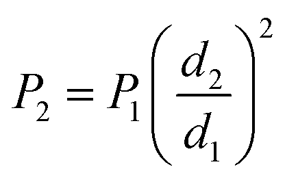 | (2) |
Since the intention was to allow for sample scanning for complete treatment and/or patterning, the exposure time t1 determined the scanning speed of the laser head, controlled by a three-axis CNC system (Bosch–Rexroth). To avoid anomalous power-up (threshold and shutter) events and acceleration effects, irradiation began outside of the sample, scanned across at constant speed and finished outside of the sample. A point on a sample is thus irradiated during t1 as the beam diameter d2 scans centred across it at a speed v:
| v = d2/t1 | (3) |
In a single line scan, eccentric points will receive shorter exposure times and lower power due to a Gaussian beam profile. Therefore, for full sample treatments, several line scans were performed at 50% track overlap, assuming d2 is measured at the full-width at tenth maximum (FWTM) (worst case) (Fig. 1).
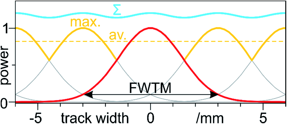 | ||
| Fig. 1 Cross-section of 50%-overlapped (at the FWTM) Gaussian power profiles vs. track width, resulting from laser scanning. Highlighted are maximum power crests (yellow max.), their average (yellow dashed av.) and the sequential sum of every passage (blue Σ). | ||
A point on the sample will therefore experience either (1) the summed power from every passage (Fig. 1: Σ) or (2) only the site-specific maximum power (Fig. 1: max.). In our previous study we observed that accumulated exposures of equal power or time had no effect on the SWCNTs, only producing changes upon an increase of either.20 Thus, we believe the second scenario to be more realistic, with a sample-average 84% of the peak power (Fig. 1: av.). If the measured beam diameter were to correspond to a value below the FWTM (e.g., 1/e2, 1/e, full width at half-maximum), the radiation profile would be smoother and the average closer to peak power.
2.3 Material characterisation
Raman spectroscopy (Renishaw inVia) was carried out with 532 nm (2.33 eV) CW excitation and a 50× objective with 0.75 numerical aperture (see results for beam spot diameter). The laser power was set to 8.8 μW (below a modification threshold of 17.6 mW as calculated previously20 and confirmed here), and spectra were acquired between 100 and 3500 cm−1 with a 2400 line per mm grating. Spectra were baseline corrected through full-range noise linear regression. Standard indicators were extracted from the peak position and intensity ratios of Lorentz-fitted deconvolutions of Raman modes RBM, D, G+ and G′. Tube diameters dt were calculated with dt = 234/ωRBM.36 Argumentation on the origin of these modes and the validity of their use can be found in our previous study.20 Although peak ratios are unaffected by inter-spectrum normalisation, we have kept multi-spectrum datasets non-normalised to observe concentration- and crystallinity-sensitive effects in the Raman signal. The initial local radiation was studied in situ, while the scaled-up radiation was analysed in 12 mm line maps with a 0.5 mm step across a single laser-treated track, post treatment and ex situ.In the same manner, 2-point electrical resistance measurements were performed on a micromanipulator stage (Signatone S-1160B-8N), along a 12 mm line map with a 0.5 mm step, centred across a single track. Two silver needles, each mounted on 3-axis μm adjustment screws (Signatone S-725, 10 μm resolution), contacted the SWCNT mat, penetrating its full thickness with a tip separation of ca. 200 μm. This was calibrated optically, through an in situ optical microscope (Leica StereoZoom, 1.5× objective, 10 μm resolution) and a μm ruler. The needle leads were PC-controlled and set at a constant voltage source of 2 V. Five line maps were carried out at different locations along the track.
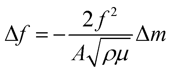
For gas adsorption measurements, a fully scanned SWCNT sample region was dispersed in isopropyl alcohol with 7 min ultrasound, drop casted on a gold-coated microbalance AT-cut (∼35°) quartz crystal and dried in ambient conditions. The water-cooled (20 °C) microbalance (MDC SQM-310) was placed in a steel vacuum chamber and pumped down to a base 1.2 × 10⁻⁷ kPa by turbo and rotary pumps. Once isolated with a gate valve, the chamber was injected with hydrogen through a needle valve up to pressures between ca. 0.4 and 13.3 kPa, measured with a capacitive gauge (MKS instruments Baratron). For each pressure iteration, the in situ shift in resonance frequency Δf (eqn (4)) of the quartz crystal at saturation, with respect to that in vacuum, determined the adsorbed H2 mass Δm based on Sauerbrey's equation:
 | (4) |
SWCNT/ethanol dispersions, drop-casted on copper grids with a lacey carbon film (Gatan) were observed in a transmission electron microscope (TEM) (JEOL 2100F) at 200 kV. Thermogravimetry (TG) was carried out in a combined setup (Netzsch-Gerätebau Jupiter 449) with 10 mg of pristine and treated SWCNTs, heated at 10 °C min−1 up to 800–900 °C in air.
3 Results and discussion
3.1 Pristine SWCNT mats
The prepared SWCNT mats are 20 to 30 μm thick and are composed of randomly aligned ∅ 10–40 nm bundles (Fig. 2a). Amorphous carbon covers the bundles (Fig. 2b) and permeates the sample in nodules, along with catalyst particles (Fig. 2a – bottom right). TG confirms the abundant carbonaceous species with a strong, early combustion around 400 °C, which slows down and saturates around 600 °C (Fig. 2c).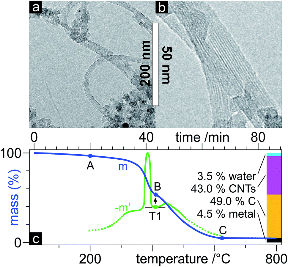 | ||
| Fig. 2 TEM micrographies (a and b) of the pristine SWCNTs and TG mass (m) and (mirrored) derivative mass (−m′) curves (c) with global proportion bars. | ||
CNT literature is awash in mentions of difficultly quantifiable purity. Two TG-based purity parameters, T1% and mR, are generally accepted parameters in commercial tubes.39 Hereby, the mass and its derivative (equivalent to differential scanning calorimetry data) are used to identify different mass loss events and quantify water, CNT, non-CNT carbon, and metal/non-volatile species. The first is taken at 200 °C, point up to which the mass loss is attributed to adsorbed/trapped sample water (Fig. 2c – point A). Point B delimits the CNT species and arises from the T1 abscissa, the minimum between the strongest exothermal peak in the mirrored derivative mass (−m′) and the following peak. Further mass loss corresponds to other carbonaceous species until 625 °C (point C), followed by non-volatiles/non-carbonaceous species. These four proportions thus allow for a carbonaceous purity of the CNTs (CNTs/CNTs + C), referred to as T1%, and the residual mass mR, both corrected for initial moisture. Here, we find a T1% of 46.7% and a mR of 4.7%.
3.2 Local laser radiation: power and time
Their initial Raman signal (Fig. 3: red spectrum at 0 mW) presents an ID/IG+ of 0.09 and an IG′/ID of 3.01. The radial breathing mode (RBM) is dominated by two main contributions (Fig. 3: inset against back plane), deconvoluted to 167.94 and 186.82 cm−1, indicating a very narrow tube diameter distribution of 1.25 to 1.39 nm (inversely).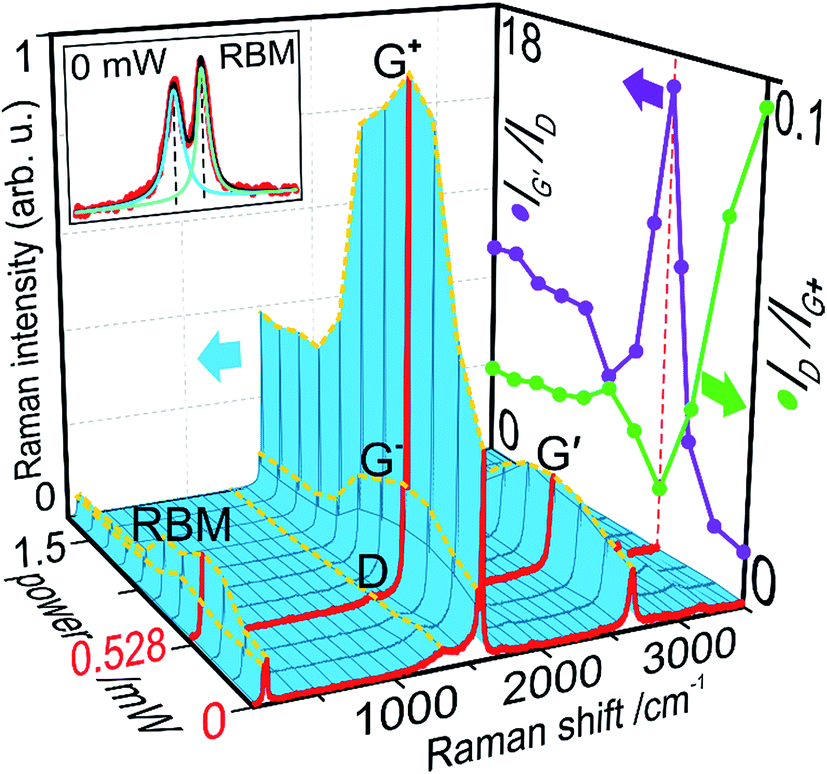 | ||
| Fig. 3 Raman signal vs. power (blue 3-D surface) with highlighted (red) initial (0 mW) and optimal (0.528 mW) spectra, peak intensity variations (yellow dashed lines) of modes RBM, D, G−, G+ and G′, and a zoomed-in RBM (top-left rear plane); ID/IG+ and IG′/ID ratios (right-hand plane). | ||
As the radiation power was increased, the intermittent Raman signal increased for all order-induced modes, RBM, G and G′ (Fig. 3: dashed yellow peak paths). This strong non-proportional intensification reaches a maximum at 0.528 mW (Fig. 3: red spectrum at 0.528 mW). Since sample concentration did not increase nor did tube ends bundle, which are possible causes for signal increase,40 we can posit impurity removal and recrystallization based on the following: the signal increase is not proportional for any mode; G+ grows proportionately more than G− and RBM; only one RBM peak grows, while the other is sustained. This also indicates metallic tube removal at this wavelength (532 nm),27,29,30 as previously clarified.20 As to the disorder-induced D mode, a slight initial rise, possibly due to the removal of adsorbed water, is followed by an abrupt drop. This, to a certain extent, could explain an initial dampening of the other vibrational modes through the presence of carbonaceous contaminants. Yet the non-proportional behaviour of said modes, again points to competing mechanisms, removing defects, impurities and metallic tubes. Above 0.528 mW, all modes experience a more gradual decay, stabilising at levels below their initial values. This can be explained by tube damage and loss, with energy densities above that tolerable by these SWCNTs.
Given that proportionality – or a lack thereof – is key in Raman data, the ID/IG+ and IG′/ID ratios further support the current narrative, both reaching their extremes at the same power of 0.528 mW (Fig. 3: right-hand plane). As previously seen, the defect density ID/IG+ is the first to react to the radiation with a near straight drop to a minimum 0.019. The purity index IG′/ID barely changes after the first irradiation and then brusquely peaks at 16.7. These indicators further reveal the damaging effect of laser radiation above this power, both decaying until 0.88 mW. Tube damage, opening and burning contribute to these fluctuations, with defect density and purity often mirroring each other. Passed this point, these two ratios stabilise at values in between their extremes. These indications of increasing graphitisation and purification point to 0.528 mW as an approximate optimal power P1.
The next parameter necessary for a meaningful optimisation of the energy input is the exposure time. To this end, the power was fixed at P1 during a sweep of the exposure time with intermittent Raman scans (Fig. 4). Again, the same non-proportional amplification of RBM (one of two peaks), G (mainly G+) and G′, and decline of D, are observed, saturating around 0.3 s.
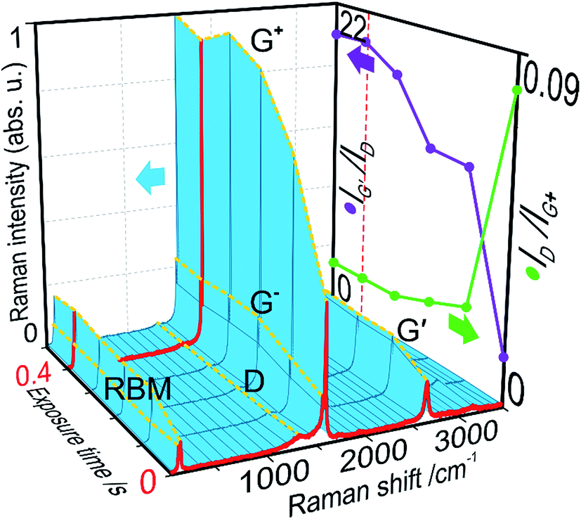 | ||
| Fig. 4 Raman signal vs. exposure time (blue 3-D surface) with highlighted (red) initial (0 s) and optimal (0.4 s) spectra, peak intensity variations (yellow dashed lines) of modes RBM, D, G−, G+ and G′; ID/IG+ and IG′/ID ratios (right-hand plane). | ||
ID/IG+ drops promptly at 0.1 s and steadies by 0.3 s, to a minimum of 0.012. As previously observed, impurity removal is a longer process, and thus IG′/ID reaches its maximum 20.74 in a less pronounced manner at 0.4 s. Therefore, a combined optimum is reached for both markers at t1 0.4 s. In view of the subsequent scale-up, this time was taken where the observed markers plateaued, without accommodating for any further signal (isolated peaks) increase. This sweep saw an improvement upon both optimised markers, compared to the power sweep, likely due to the extremely reduced time scale, far exceeded at 130 s exposures. P1 and t1 thus provide a measure of energy input for optimal laser healing and purification of the SWCNTs, 0.4 s of 0.528 mW, or 0.21 mJ.
3.3 Scale-up
At this point, we had optimised the laser energy based on Raman indicators, at a constant irradiated area in the μm scale. A scale-up to an industry relevant mm scale, carried out at constant irradiance, following eqn (2), was fed with the obtained parameters: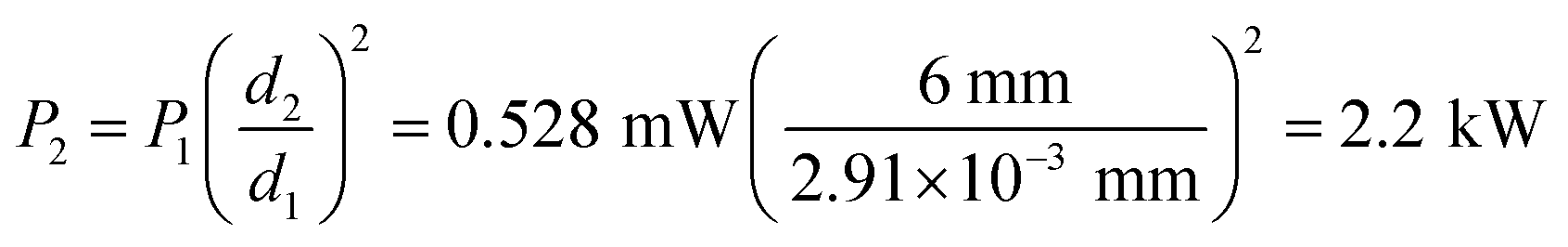
This value for P2 greatly surpasses the maximum available 500 W and is more than CNTs can sustain. For the scanning speed v, d2 and t1 in eqn (3) return 15 mm s−1. To confirm the excessive power, a sample was treated with a 15 mm s−1 scan at 500 W and 6 mm spot size, with no remaining tubes as per Raman. Although scaling up laser radiation across different lasers and wavelengths can prove challenging, with absorption characteristics at play, we evaluated a possible false premise, namely d1.
This Raman laser beam diameter was calculated based on the Raman signal variation while scanning across an amorphous carbon fibre of known diameter.20 We challenged said measurement with an alternate approach: (1) a power meter was partially covered with a compacted opaque (verified) layer of SWCNTs, as particularly good light absorbers, to avoid reflection and diffraction; (2) the power meter was placed on the sample stage with its surface at the focal plane and the CNTs blocking any transmission; (3) moving the power meter in a straight line across the focal plane, the displacement was measured for a power variation from 0 to its maximum, yielding 25.1 μm (Fig. 5).
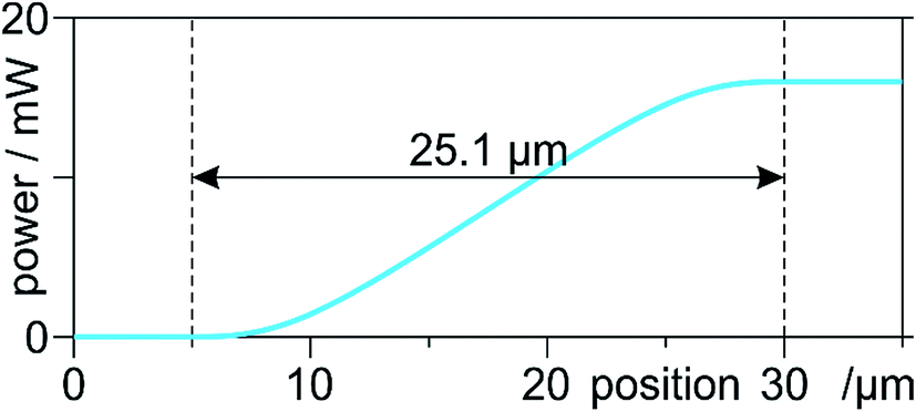 | ||
| Fig. 5 Measured power vs. stage position. The transition of ca. 25.1 μm is the average of five scans. | ||
Now, there is inherent complexity in measuring Gaussian-profile beam diameters without a beam profiler. The initial approach might fall short due to the sensitivity threshold of the Raman spectrometer, in the parts-per-million for carbon phases, at the centre of the beam. Yet the wide-ranging, asymptotic arms of the Gaussian profile, when falling below said threshold, were possibly cut off, underestimating d1. On the other hand, this new approach can be seen as an overestimation. Indeed, measures were taken to avoid reflection and diffraction, yet they cannot be ruled out completely; not to mention, fluorescence and stray light. These phenomena falsely widen the detection area for the power meter. This does not invalidate our previous results, since it only changes the irradiance values, not the underlying phenomena. In order to build upon our proof of concept from said study, we continued with this new value for d1. Finally, note that this is not a direct transposition of radiation from the μm to the mm scale, since it only considers the emission, not the absorption, which is strongly dependent on wavelength. Thus, this remains an approximate reference for mm-scale modification of SWCNTs.
This 8-fold beam diameter was referred into eqn (2), returning a P2 of 30.17 W. This time, a 15 mm s−1 scan at 30 W did not visibly burn the tubes and was further probed. Based on the satisfactory results, resembling what was expected, the apparent fruition of this scale-up was validated with enough accuracy for the frame of this study.
Electron microscopy cannot carry the burden of proof concerning local/environmental disorder. The very local nature of TEM does not allow for conclusive results, furthermore its preparation through sonication rises questions with respect to the homogenous reallocation of impurities throughout the sample and ultrasound is known to cause defects in SWCNTs. Nonetheless, the laser-treated sample was observed in TEM, unfortunately, with no major differences compared to the pristine state. TG, however, provides information on a much greater sample size and is thus more statistically relevant. Fig. 6 shows a much higher oxidation-onset temperature for the laser-treated SWCNTs, pointing to a higher degree of graphitization and less defects and disorder. A T1% of 90.7% almost doubles the pristine 46.7% SWCNT purity.
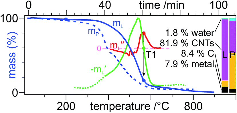 | ||
| Fig. 6 TG mass (mL) (blue) and (mirrored) first (−m′L) (green) and second (m′′L) (red) derivative curves with global proportion bars of the laser-treated (L) samples, as well as the mass curve (mP, dashed) and proportion bars of the pristine (P) sample. In the absence of a distinct second peak in −m′L, its inflection point (local maximum in m′′L) determines T1.39 | ||
A single laser scan across a sample was then further analysed by Raman spectroscopy and electrical resistance measurements (Fig. 7). The plotted ID/IG+ and IG′/ID (Fig. 7a) along a 12 mm line across the track show different extensions in their deviation from their initial pristine values, but both exceed the 6 mm track. This is to be expected, since photothermal and photochemical effects govern the laser treatment.41 The thermal component and the excellent heat conduction of SWCNTs thus produce a heat-affected zone (HAZ) beyond the irradiated area. Judging from IG′/ID, the HAZ extends ca. 10 mm, an extra 2 mm on either side of the track. Although not smooth, both plots present bell-shaped curves. That of the defect density, ID/IG+, deviates from its pristine state 0.5–1 mm beyond the track, half as much as the purity IG′/ID. This indicates that defects are less sensitive to temperature than impurities. Peak values of either ID/IG+ and IG′/ID of ca. 0.02 and 17, respectively, did not reach those from the local radiation (0.01 and 20, respectively), possibly from a slightly overestimated d1.
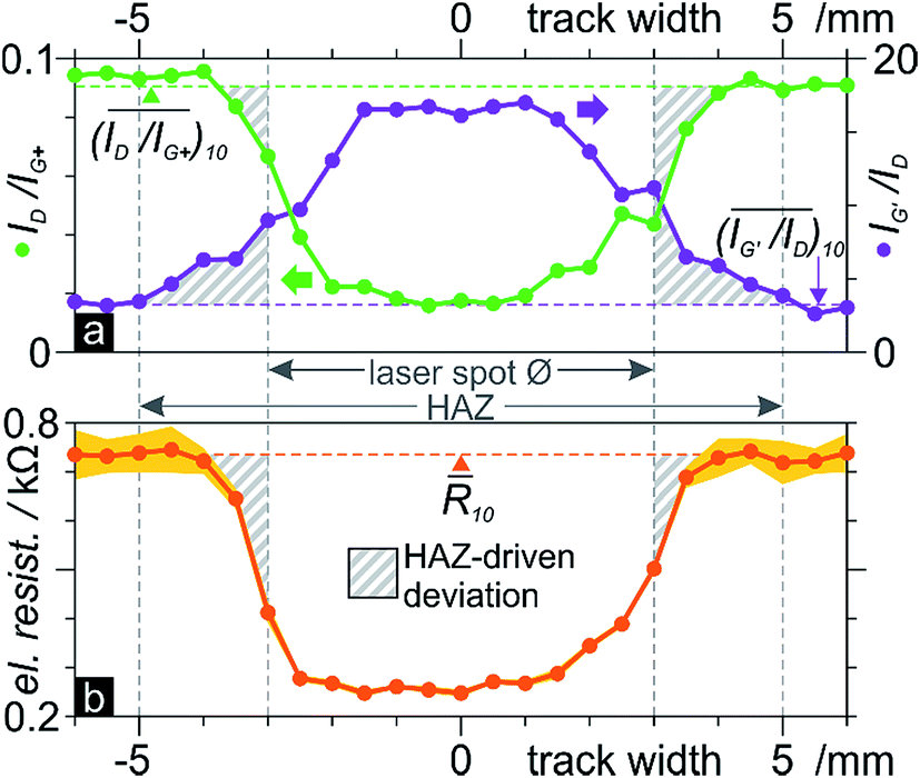 | ||
| Fig. 7 12 mm scans across a laser track at 0.5 mm steps of: (a) Raman ID/IG+ (left, green) and IG′/ID (purple, right) ratios; (b) 200 μm electrical resistance (five scan average points with σ surface). The dashed lines indicate 10-point pristine averages. The hashed surface denotes data points that deviate from this value, outside the track, and are thus HAZ-driven. | ||
Since the scaled-up radiation was performed with 940 nm (1.39 eV) vs. the local 532 nm (2.33 eV), the slight disparity in Raman parameters could be discussed by means of the absorption characteristics at each wavelength. However, chirality-dependent absorption mechanisms and our polychiral sample render this discourse moot.
The electrical resistance also presents a bell-shaped curve, from a pristine 0.74 kΩ to 0.25 kΩ in the middle of the track (Fig. 7b). That is a third of the resistance in the laser-treated tubes. The negligible standard deviation compared to the variability outside the track shows how laser radiation homogenises the sample. The plot resembles that of ID/IG+, in its asymmetricity and width. This makes sense, given that electrical conduction in a SWCNT occurs through the delocalised π-cloud electrons. These are provided by the orthogonal pz orbitals which, in the presence of crystal defects, are distorted or absent (vacancies). Although tube wall contaminants can perturb its electronic states and cause depletion or accumulation of carriers42 and purification does improve conduction, crystallinity seems to have a greater influence. The improved conductivity is also attributable to the known preferential removal of semiconducting tubes with near infrared wavelengths (785–1064 nm),27 leaving primarily metallic tubes due to the 940 nm radiation. This therefore confirms our previously theorised preferred conduction paths, along the laser-annealed track, versus other directions, and confirms the findings of Del et al. who improved conductivity in graphene inks with laser annealing.35
Finally, the effect of the laser treatment on hydrogen adsorption was studied on samples taken from the centre of the track and an unaffected region. A commercial SWCNT sample was also put to the test to provide a normalised context regarding methodology and achievable pressures. All three samples show an uninterrupted mass/pressure proportionality, which slows down at 3–5 kPa towards apparent saturation (Fig. 8a). The laser-annealed tubes show a 30 to 50% adsorption compared to the pristine tubes throughout the range of probed pressures, with a final ca. 0.5 and 1 wt% (respectively) around 14 kPa. The commercial tubes maintain 20 to 30% superior values over the pristine tubes, approaching them around saturation followed by a slight divergence, reaching around 1.3 wt%. Crystallinity, purity and tube diameters are summarised in Fig. 8b for structural correlations.
 | ||
| Fig. 8 (a) H2 gas adsorption (with deposited mass and σ areas) as a function of H2 pressure, (b) ID/IG+ (green bars), IG′/ID (purple bars) and tube diameter (dt) (black segments) distribution (as per RBM frequencies) of commercial (C), pristine (P) and (scaled up) laser-annealed (L) samples. | ||
The governing hydrogen storage mechanism is currently unclear,43 but there is consensus on the fact that defective CNTs perform better.43,44 CNTs are extremely porous and offer high surface area for adsorption on and in the tubes, with overlapping potential fields on opposite walls creating attractive forces.45 Hydrogen storage is physisorption-like in nature, with preferential adsorption on defect sites.43,44 This correlates perfectly with our results, showing the laser-annealed tubes, with less defects (Fig. 8b), well below the storage capacity of the pristine tubes. Furthermore, larger tube diameters and small bundles improve hydrogenation, by freeing up surface in otherwise restrained tubes.44 This explains the superior capacity of the commercial sample, which, although equally defective as the laser-treated tubes, has far larger tubes than the other samples (Fig. 8b: black segments). No significant differences in the adsorption kinetics were observed, with 120 to 80 s saturation times (from inlet to resonance frequency stabilisation) throughout the range of pressures. For comparison, Pd films (less porous) saturate in around 50 s under equal conditions,37 and multiwall CNTs do so in under 100 s.46
Concerning the effect of impurities in CNT samples, studies often compare pristine and acid-purified tubes: claims of higher H2 uptake are often correlated with higher purity due to enhanced surface area45 or opened ends.47 However acid treatments are known to cause severe damage in the crystal lattice,10 thus clouding said results with undiscussed competing effects of multiplied active defect sites. Among our directly comparable samples, pristine and laser-annealed, the latter are much purer due to the laser treatment, yet fared unfavourably with respect to H2 uptake. This either contradicts the literature or marks crystallinity as decisive in the corresponding adsorption mechanisms. Considering the removed metal catalysts – advantageous for gas adsorption47 – during laser radiation, the same argument can therefore be made for the governance of crystallinity.
Dedicated hydrogenation studies have tested pressures in the 10 MPa range, with earlier mixed reports and overestimated results, now stagnating at around 1.7 wt%.43 This not dissimilar value at an order of magnitude the pressure, provides context and understanding of the qualitative differences in our samples (note that our samples were not pre-baked or moisture-free sealed, and can thus contain up to 10 wt% water, obscuring results). This is a further confirmation that laser radiation recrystallises and purifies the SWCNTs. Lastly, the reduced standard deviation, as with the electrical resistance, underlines the homogenising effects of the radiation.
4 Conclusions
We optimised a 25 μm spot of 532 nm laser radiation on SWCNTs, extracting 0.528 mW of power and 0.4 s of exposure time from comparative Raman peak intensity ratios that maximise crystallinity and purity. This was scaled-up at constant fluence to a 6 mm spot, scanning-head, 940 nm laser, translating to 30 W and 15 mm s−1 scanning.A laser line-scan across a sample reached Raman ratios close to those at the μm scale. A heat-affected zone of above-average purity and crystallinity reached respectively 2 and 1 mm on either side of the track, confirming slow, thermal purification and photonic excitation-driven recrystallisation. The centre of the track showed an average 250 Ω electrical resistance, a third of the 750 Ω in the untreated tubes. These points correlated more closely with those of the crystallinity, in shape and extension, indicating the dominant effect of lattice defects on electrical resistance, which disrupt the delocalised e− cloud, compared to impurities. Laser-treated tubes from the centre of the track demonstrated 30 to 50% the hydrogen adsorption capacity of untreated tubes. Since hydrogen uptake occurs mainly at defect sites, this implies more crystalline and pure laser-annealed tubes.
This scaled-up, simple, efficient and ambient treatment puts forth (1) abundant and upfront indications that laser radiation effectively heals defects, removes impurities and homogenises the sample, as confirmed by Raman spectroscopy, electrical resistance, hydrogen adsorption and TG. Furthermore, this (2) adds to the validity of extensively used, yet contested Raman ID/IG+ and IG′/ID ratios as indicators of crystallinity and purity. Furthermore, (3) the application-relevant mm scale brings this promising technique closer to industry with sights on higher quality tubes, cheaper synthesis and recovery of unavoidable processing-related damage. This can be extended to unachievable tube qualities, due to alternative complex organic precursors,48 bringing such CNTs up to industry standards and closer to sustainability. A final corollary of damage recovery is (4) the possible rejuvenation of electrical cycling or wear-related damage to CNT materials, to extend their duty life.
Advancing controllability of CNT synthesis, chirality purification and tube quality could benefit from this swift and scalable CNT treatment to reach new standards in CNT quality, recover CNT damage, and generally improve performance in CNT-based materials and devices.
Acknowledgements
This work was supported by the SUMA2 Network Project, 7th Framework Program of the European Commission (IRSES Project No. 318903), and the CREATE-Network Project, Horizon 2020 Program of the European Commission (RISE Project No. 644013). Many thanks to Matias Miguez for the electrical resistance set-up, Prof. Volker Presser for the Raman spectrometer, Aura Tolosa for TEM imaging and Marco Zeiger for TG. M.Sc. Federico Lasserre is kindly acknowledged for corrections and discussions. D. D.-D. thanks the 11130555 Fondecyt project from the Chilean Government.Notes and references
- L. V. Radushkevich and V. M. Lukyanovich, Zh. Fiz. Khim., 1952, 26, 88 CAS.
- S. Iijima, Nature, 1991, 354, 56–58 CrossRef CAS.
- B. G. Demczyk, Y. M. Wang, J. Cumings, M. Hetman, W. Han, A. Zettl and R. O. Ritchie, Mater. Sci. Eng., A, 2002, 334, 173–178 CrossRef.
- M. M. Shulaker, G. Hills, N. Patil, H. Wei, H.-Y. Chen, H.-S. P. Wong and S. Mitra, Nature, 2013, 501, 526–530 CrossRef CAS PubMed.
- M. F. L. De Volder, S. H. Tawfick, R. H. Baughman and A. J. Hart, Science, 2013, 339, 535–539 CrossRef CAS PubMed.
- J. A. Robinson, E. S. Snow, Ş. C. Bǎdescu, T. L. Reinecke and F. K. Perkins, Nano Lett., 2006, 6, 1747–1751 CrossRef CAS PubMed.
- M. Wong, M. Paramsothy, X. J. Xu, Y. Ren, S. Li and K. Liao, Polymer, 2003, 44, 7757–7764 CrossRef CAS.
- Y. Piao, B. Meany, L. R. Powell, N. Valley, H. Kwon, G. C. Schatz and Y. Wang, Nat. Chem., 2013, 5, 840–845 CrossRef CAS PubMed.
- J. Stein, B. Lenczowski, E. Anglaret and N. Fréty, Carbon, 2014, 77, 44–52 CrossRef CAS.
- P. G. Collins, in Oxford Handbook of Nanoscience and Technology: Volume 2: Materials: Structures, Properties and Characterization Techniques, ed. A. V. Narlikar and Y. Y. Fu, 2010, pp. 1–73 Search PubMed.
- H. Jia, Y. Lian, M. O. Ishitsuka, T. Nakahodo, Y. Maeda, T. Tsuchiya, T. Wakahara and T. Akasaka, Sci. Technol. Adv. Mater., 2005, 6, 571–581 CrossRef CAS.
- S. Bandow, A. Rao and K. Williams, J. Phys. Chem. B, 1997, 5647, 8839–8842 CrossRef.
- K. B. Shelimov, R. O. Esenaliev, A. G. Rinzler, C. B. Huffman and R. E. Smalley, Chem. Phys. Lett., 1998, 282, 429–434 CrossRef CAS.
- A. Suri and K. S. Coleman, Carbon, 2011, 49, 3031–3038 CrossRef CAS.
- H. J. Park, M. Park, J. Y. Chang and H. Lee, Nanotechnology, 2008, 19, 335702 CrossRef PubMed.
- Y. Wang, J. Wu and F. Wei, Carbon, 2003, 41, 2939–2948 CrossRef CAS.
- P. Garg, J. L. Alvarado, C. Marsh, T. a. Carlson, D. a. Kessler and K. Annamalai, Int. J. Heat Mass Transfer, 2009, 52, 5090–5101 CrossRef CAS.
- S. Song, H. Yang, R. Rao, H. Liu and A. Zhang, Catal. Commun., 2010, 11, 783–787 CrossRef CAS.
- K. S. Munir and C. Wen, Crit. Rev. Solid State Mater. Sci., 2016, 8436, 1–20 Search PubMed.
- N. Souza, M. Zeiger, V. Presser and F. Mücklich, RSC Adv., 2015, 5, 62149–62159 RSC.
- A. V. Krasheninnikov, P. O. Lehtinen, A. S. Foster and R. M. Nieminen, Chem. Phys. Lett., 2006, 418, 132–136 CrossRef CAS.
- M. Monthioux and J. C. Charlier, Carbon, 2014, 75, 1–4 CrossRef CAS.
- T. Nakamiya, T. Ueda, T. Ikegami, F. Mitsugi, K. Ebihara, Y. Sonoda, Y. Iwasaki and R. Tsuda, Thin Solid Films, 2009, 517, 3854–3858 CrossRef CAS.
- D. B. Geohegan, H. Schittenhelm, X. Fan, S. J. Pennycook, A. A. Puretzky, M. A. Guillorn, D. A. Blom and D. C. Joy, Appl. Phys. Lett., 2001, 78, 3307 CrossRef CAS.
- U. Brand, H. Hippler, L. Lindemann and J. Troe, J. Phys., 1990, 94, 6305–6316 CAS.
- L. Pang, L. Prochazka and R. Quezada, Fuel and Energy Abstracts, 1995, 36, 189 Search PubMed.
- A. Roch, T. Roch, E. R. Talens, B. Kaiser, A. Lasagni, E. Beyer, O. Jost, G. Cuniberti and A. Leson, Diamond Relat. Mater., 2014, 45, 70–75 CrossRef CAS.
- H. Liu, D. Nishide, T. Tanaka and H. Kataura, Nat. Commun., 2011, 2, 309 CrossRef PubMed.
- M. Mahjouri-Samani, Y. S. Zhou, W. Xiong, Y. Gao, M. Mitchell and Y. F. Lu, Nanotechnology, 2009, 20, 495202 CrossRef CAS PubMed.
- H. Huang, R. Maruyama, K. Noda, H. Kajiura and K. Kadono, J. Phys. Chem. B, 2006, 110, 7316–7320 CrossRef CAS PubMed.
- J. Yotani, S. Uemura, T. Nagasako, H. Kurachi, H. Yamada, T. Ezaki, T. Maesoba, T. Nakao, M. Ito, T. Ishida and Y. Saito, Jpn. J. Appl. Phys., 2004, 43, L1459–L1462 CrossRef.
- K. F. Chen, K. C. Chen, Y. C. Jiang, L. Y. Jiang, Y. Y. Chang, M. C. Hsiao and L. H. Chan, Appl. Phys. Lett., 2006, 88, 2005–2007 Search PubMed.
- D. N. Ventura, Synthesis of Cross-Linked Carbon Nanotube Mats and Their Applications, Florida State University, 2011 Search PubMed.
- B. Peng, M. Locascio, P. Zapol, S. Li, S. L. Mielke, G. C. Schatz and H. D. Espinosa, Nat. Nanotechnol., 2008, 3, 626–631 CrossRef CAS PubMed.
- S. K. Del, R. Bornemann, A. Bablich, H. Schäfer-Eberwein, J. Li, T. Kowald, M. Östling, P. Haring Bolívar and M. C. Lemme, 2D Mater., 2015, 2, 11003 CrossRef.
- C. Fantini, A. Jorio, M. Souza, M. S. Strano, M. S. Dresselhaus and M. A. Pimenta, Phys. Rev. Lett., 2004, 93, 1–4 Search PubMed.
- R. El Far, D. E. Diaz-Droguett, S. Rojas, J. I. Avila, C. P. Romero, P. Lievens and A. L. Cabrera, Thin Solid Films, 2012, 522, 199–203 CrossRef CAS.
- E. Mosquera, D. E. Diaz-Droguett, N. Carvajal, M. Roble, M. Morel and R. Espinoza, Diamond Relat. Mater., 2014, 43, 66–71 CrossRef CAS.
- R. Jansen and P. Wallis, Mater. Matters, 2009, 4, 23 CAS.
- K. Ramadurai, C. L. Cromer, A. C. Dillon, R. L. Mahajan and J. H. Lehman, J. Appl. Phys., 2009, 105, 93106 CrossRef.
- K. Hurst and A. Dillon, J. Phys. Chem. C, 2008, 112, 16296–16300 CAS.
- M. J. O. Connell, D. Ph and F. Group, Carbon Nanotubes Properties and Applications, 2006 Search PubMed.
- S. M. Lee, K. H. An, W. S. Kim, Y. H. Lee, Y. S. Park, G. Seifert and T. Frauenheim, Synth. Met., 2010, 121, 1189–1190 CrossRef.
- K. Shen, H. Xu, Y. Jiang and T. Pietraß, Carbon, 2004, 42, 2315–2322 CrossRef CAS.
- G. E. Ioannatos and X. E. Verykios, Int. J. Hydrogen Energy, 2010, 35, 622–628 CrossRef CAS.
- M. Morel, E. Mosquera, D. E. Diaz-Droguett, N. Carvajal, M. Roble, V. Rojas and R. Espinoza-González, Int. J. Hydrogen Energy, 2015, 40, 15540–15548 CrossRef CAS.
- S. Banerjee, S. Murad and I. K. Puri, Proc. IEEE, 2006, 94, 1806–1814 CrossRef CAS.
- N. Souza, F. Lasserre, A. Blickley, M. Zeiger, S. Suárez, M. Duarte, V. Presser and F. Mücklich, RSC Adv., 2016, 72596–72606 RSC.
| This journal is © The Royal Society of Chemistry 2017 |