 Open Access Article
Plasmon enhanced light absorption in aluminium@Hematite core shell hybrid nanocylinders: the critical role of length
Ezequiel R. Encina *,
Nicolás Passarelli and
Eduardo A. Coronado
INFIQC, UNC, CONICET, Departamento de Fisicoquímica, Facultad de Ciencias Químicas, Córdoba, Argentina. E-mail: ezencina@fcq.unc.edu.ar; Fax: +54-351-433-4180; Tel: +54-351-535-3866
First published on 12th January 2017
Abstract
The light absorption as well as the near field enhancements properties of Al@α-Fe2O3 core shell hybrid nanocylinders (HNs) have been systematically studied by means of Discrete Dipole Approximation simulations. The Al@α-Fe2O3 HNs consist of a right circular cylinder Al core, wrapped by a circular section of an α-Fe2O3 shell, both having the same finite length L. A general and useful methodology has been implemented to assess separately the partial contributions to the absorption spectrum of each component of the Al@α-Fe2O3 HN. The employed methodology can be applied not only to those HNs studied here but also to any other nanostructure with arbitrary geometry and several components providing relevant information not accessible through standard spectroscopic techniques. The absorption spectra have been employed to calculate the absorbed photon flux ϕ within the α-Fe2O3 shell. According to the HN size, plasmon enhanced light absorption in the α-Fe2O3 shell of the Al@α-Fe2O3 HNs is evidenced, which is attributed to a plasmon-induced energy transfer mechanism based on near field enhancements. The effect of the HN length on the absorbed photon flux ϕ is an important issue that has not been addressed yet, as only infinitely long HN has been considered in previous studies. It is demonstrated that the HN length L has a crucial influence on the absorbed photon flux ϕ, as it is the main structural parameter that allows us to tune the dipole plasmon resonance of the Al core into the visible region. Furthermore, it is shown that Al cores lead to larger ϕ values than the typical plasmonic metals Ag and Au. The results presented in this work point out that the HN length should be explicitly taken into account for an optimum design of core shell hybrid cylindrical nanostructures with enhanced or improved photoactive properties.
Introduction
Nanostructures composed of semiconductor metal oxides have attracted great attention during the last few decades due to their applications as photoactive materials capable to transform light energy into electric or chemical energy.1–3 Although solar radiation is the biggest source for clean, sustainable, abundant and easily accessible light energy, its broad utilization to satisfy the energy demand has been retarded by the high cost and low efficiency of the available photoconversion materials and devices.4,5 The efficiency of the most widely used semiconductors materials in photocatalytic and photovoltaic devices is limited mainly due to their inability to use visible light and to the fast recombination of photogenerated electron–hole pairs before they migrate to the surface.6 Among the several strategies implemented to overcome these limitations and to enhance the photoconversion efficiencies, stands out the combination of plasmonic metals and semiconductor metal oxides into single hybrid nanostructures.7–12 In recent years, progress has been made in understanding the plasmonic metal–semiconductor interactions, which lead to the identification of at least three different mechanisms that contribute to enhance the photoconversion efficiency: light trapping based on scattering, hot electron/hole transfer and plasmon-induced energy transfer based on near field.13–16Hematite (α-Fe2O3) is one of the most thermodynamically stable iron oxides, it is abundant, inexpensive, non-toxic and stable in aqueous environment.17 Its optical bandgap energy is reported to be between 1.9 and 2.2 eV (corresponding to 650 and 560 nm wavelengths respectively) depending on the sample preparation technique, which results in a theoretical maximum photocurrent density under AM 1.5 G illumination conditions of 12.6 mA cm−2, corresponding to a maximum solar to hydrogen (STH) conversion efficiency of about 15%.18,19 In addition, it has been proposed that its valence band alignment is ideal to catalyze the oxygen evolution reaction.20 These properties make α-Fe2O3 a promising material for the construction of photoanodes useful for photoelectrochemical water splitting.21,22 However, α-Fe2O3 photoanodes exhibits low internal quantum efficiency, a feature that has been attributed to their slow water oxidation kinetics and short diffusion length of the photogenerated minority charge carriers (holes), resulting in significant losses due to electron/hole recombination.23 Besides, the α-Fe2O3 conduction band edge is lower than the reduction potential of water, therefore a large overpotential is required to drive the hydrogen evolution.24,25 The incorporation of plasmonic materials in this structures could greatly overcome this shortcoming. Plasmonic metal nanoparticles are recognized for supporting localized surface plasmon resonances (LSPRs), which originate large absorption and scattering cross sections as well as near field enhancements.26 Gold (Au) and silver (Ag) are the plasmonic metals most widely studied, whereas their nanoparticles have been employed along with photoelectrodes made of α-Fe2O3 in order to increase their STH and photocatalytic activity efficiencies.27–29 For instance, Iandolo et al. have measured a considerable improvement of photoactivity under solar simulator illumination of α-Fe2O3 photoanodes functionalized with Au nanodisk, comparing reference samples consisting of bare α-Fe2O3, an issue attributed to the plasmonic activity of Au nanodisks deposited on the electrode surface.30 More recently, Archana et al. have reported enhanced photoelectrochemical performance of a smooth chemical vapor deposited α-Fe2O3 film embedded with Au nanoparticles.31 These authors obtained about 3 times higher light absorption and photocurrent enhancement from thin α-Fe2O3 films containing Au nanoparticles than with pristine α-Fe2O3 films. Moreover, it has been proposed aluminium (Al) as an alternative plasmonic material, which exhibits plasmon resonances from the UV to the visible regions of the spectrum and extends the optically tunable range of plasmonic nanostructures beyond that of Au and Ag.32,33 Some of the attractive features of Al include its low cost, high natural abundance34 and compatibility with complementary metal–oxide–semiconductor (CMOS) technology,35 whereas its plasmonics applications comprise optical antennas36 and plasmon-enhanced spectroscopy,37 among others. Therefore, bringing together these materials, that is, α-Fe2O3 and Al, into a single hybrid nanostructure provides a reasonable strategy to design materials with enhanced photoactivity taking advantage of the properties of their individual components in a synergic way as well as to expand our current understanding on the plasmonic metal–semiconductors interactions.
The nanowire geometry is particularly relevant due to its excellent charge extraction and large absorption cross sections.38 Moreover, this geometry allow us to use Mie-formalism to obtain rigorous solutions to Maxwell's equations.39 In this respect, the absorption properties of infinitely long core shell hybrid nanowires of different compositions have been theoretically investigated by several authors in order to determine the conditions that lead to photoactive materials with a strongly enhanced (solar) light absorption, and consequently to an improved STH efficiency.40–43 Importantly, convenient methodologies to calculate separately the contributions to absorption from the different components of the hybrid nanowires, that is, the core and the shell, have been applied in these studies. For instance, Mann et al. have shown extreme light absorption in amorphous silicon thin films wrapped around silver nanowires, and suggested that metal nanowires with semiconductor shells might be ideal building blocks for photovoltaic and solar fuel.44 Recently, studies on the optical properties of infinite right circular cylindrical core-multishell hybrid nanostructures with several different compositions (α-Fe2O3–Al, Si–α-Fe2O3–Al, α-Fe2O3–Ag, Si–α-Fe2O3–Ag, among others) have been reported.45 In that work it has been shown that Al could be an excellent alternative plasmonic material to precious metals in core–multishell hybrid nanostructures with infinite length. In addition, it has been found that the maximum photocurrent density, calculated assuming ideal conditions, within the α-Fe2O3 shell of a Si(40 nm diameter)–Al(50 nm)α-Fe2O3(40 nm) nanowire reaches approximately 11.8 mA cm−2 (i.e., STH efficiency of 14.5%), whereas the absorption efficiency within the 40 nm α-Fe2O3 shell is about 93% of the theoretical maximum for bulk α-Fe2O3.46
In this work, we have studied the absorption as well as the near field enhancement properties of Al@α-Fe2O3 core shell hybrid nanocylinders (HNs) by means of systematic Discrete Dipole Approximation (DDA) simulations.47–50 The Al@α-Fe2O3 HNs consist of a right circular cylinder Al core, wrapped by a circular section α-Fe2O3 shell, both having the same finite length L. In order to perform this study a useful modification on the freely available DDSCAT 7.3 code51 has been implemented, that allow us to examine separately the absorption spectrum of each component of the Al@α-Fe2O3 HN. This strategy implemented in this work, has the important feature to be general and that can be applied not only to those HNs studied here but also to any other nanostructure with arbitrary geometry and several components. In addition, it gives information not available by means of standard experimental techniques. The geometrical parameters of the HNs have been varied systematically in a broad range, whereas the absorption spectra obtained have been used to calculate the absorbed photon flux within the α-Fe2O3 shell ϕ. Note that ϕ is a relevant quantity as it greatly determines the photoconversion efficiency of photoelectrochemical cells.19 It is shown that the length of the HNs has a crucial influence on ϕ, as by tailoring the former it is possible to switch between size regimes where ϕ can be either enhanced or suppressed. Moreover, the performance of Al as core material is compared with that of the typical plasmonics metals Ag and Au. It is important to note that this work aims to investigate the conditions that improve light absorption in the α-Fe2O3 shell, whereas issues related with phenomena subsequent to light absorption (kinetics of chemical reactions, diffusion length of charge carriers, overpotential requirements) are not addressed. To the best of our knowledge, the effect of the length of the HN on ϕ is an issue that has not been addressed yet, as only infinitely long HN has been previously considered. Thus, the present work aim to demonstrate that the HN length should be explicitly taken into account in the design of core–shell hybrid cylindrical nanostructures with improved photoactive properties.
Theoretical methods
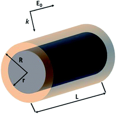
The optical properties of Al@α-Fe2O3 HNs as well as of α-Fe2O3 shells with empty internal cavity were simulated using the DDSCAT 7.3 code, which implements the DDA method.51 Detailed reports about this approximation can be found elsewhere.47–50 In this method, the nanostructure under study is represented by a cubic array of N dipoles at positions ri with dipole polarizabilities αi. As there are no restrictions in the way to locate the dipoles within the cubic array, it is possible to simulate the optical properties of arbitrarily shaped nanostructures. The dipole polarizability αi value assigned to each dipole at position ri is determined based on the dielectric constant of the composition material at position ri, which is introduced externally as input, and the lattice dispersion relation.52 In this work, the wavelength dependent complex dielectric constant of α-Fe2O3 and Al were obtained from ref. 53 and 54, respectively. Therefore, the method is able to simulate the optical properties of nanostructures with domains having different compositions. Probably, the above mentioned features constitute the most relevant characteristic of this powerful and versatile methodology able to simulate far and near field optical properties. It is important to note that the number of dipoles N used to represent a given nanostructure is a key parameter, as both the accuracy of the simulation and the computational time, increase with N. Thus, N should be chosen in such a way as to reach acceptable error tolerance. All the simulations has been performed using a lattice spacing (inter dipole distance) of 1.5 nm and N was varied from 1 × 10⁵ to 3 × 10⁶ according to the nanostructure dimensions. The length L of the cylindrical nanostructures, the external radius R and the internal radius r has been varied in the range 50–500 nm, 50–80 nm and 30–50 nm, respectively. Besides, all the nanostructures studied were located in vacuum, therefore we set the refractive index of ambient medium equal to 1. The core shell HNs, along with its geometrical parameters L, R and r, are graphically depicted in Scheme 1, along with the orientations of the electric field E0 and wave vector k of the incident light relative to the HN. In all the computations, E0 is parallel whereas k is perpendicular to the major axis of the HN.In order to obtain the absorption efficiency Qabs,i for each component i of the HN, that is, the Al core and the α-Fe2O3 shell, the electric field values calculated at each dipole position ri, |E(ri)|, were used into the following expression:19
 | (1) |
Results and discussion
Contributions to Qabs from each component of the core shell hybrid nanocylinder
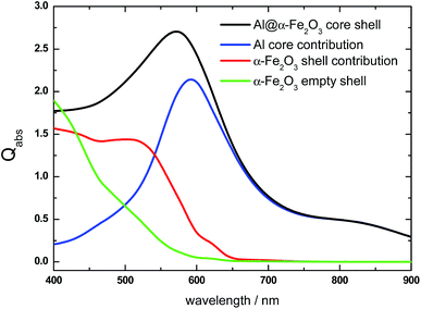
We will first examine the relative contribution to the absorption efficiency Qabs from either the core or the shell component of two HNs with different length as typical examples to have a physical insight of the changes induced in Qabs due to a change in the HN size. The Qabs spectrum of a L = 100 nm, R = 70 nm, r = 50 nm Al@α-Fe2O3 HN is shown in Fig. 1 (black curve). It can be appreciated that its main feature is an asymmetric absorption peak centered at λ = 570 nm, where the Qabs values decrease more rapidly for long that for short wavelengths. As mentioned above, the Qabs spectrum of HNs can be thought as the result of the contributions from each one of its constituent materials, that is, the core and shell components, respectively. The absorption spectrum of the Al cylindrical core (L = 100 nm, r = 50 nm) is characterized by an absorption peak at λ = 600 nm, which is attributed to the dipole LSPR (blue curve). On the one hand, it is known that due to its dielectric properties, Al nanoparticles exhibits LSPR in the UV region.55–57 However, the large redshift of the LSPR found in this case is a consequence of the relatively large size of the Al core as well as of the high refractive index local environment provided by the α-Fe2O3 shell.58,59On the other hand, the absorption contribution of the α-Fe2O3 shell is significant in the range 400 nm < λ < 650 nm (red curve). It resembles the typical absorption spectra of pure α-Fe2O3 and explains the asymmetry of the overall absorption peak.60,61 In addition, note that for λ > 650 nm, the Al core absorption overlaps with the overall absorption spectrum, indicating that the α-Fe2O3 shell absorption is negligible for such λ values. The absorption spectrum of the α-Fe2O3 shell with empty internal cavity and same dimensions (L = 100 nm, R = 70 nm, r = 50 nm) is also shown in Fig. 1 for comparison purposes (green curve). The Qabs values of the α-Fe2O3 shell with empty internal cavity noticeably decrease in contrast with the Qabs values obtained for the α-Fe2O3 shell with its internal cavity occupied by the Al core, that is, when it constitutes the HN. This enhanced light absorption effect experienced by the α-Fe2O3 shell is attributed to a plasmon-induced energy transfer mechanism, that is, to the near field enhancement generated by the excitation of the dipole LSPR in the Al core, as it will be further analyzed below. As it is becoming evident, the decomposition of the Qabs spectrum into their respective contributions constitutes a useful theoretical tool to investigate the optical properties of nanostructures with domains having different compositions. Particularly for Al@α-Fe2O3 HNs, it allows us to achieve a greater comprehension on the phenomena involved and somehow hidden in the overall absorption spectrum.
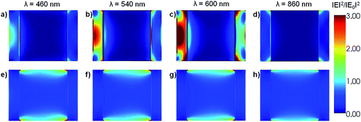
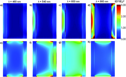
The near field enhancement at several incident wavelengths has also been calculated for both the HN as well as for the α-Fe2O3 shell with empty internal cavity to further understand the observed difference between the respective Qabs values. Fig. 2 shows 2D plots of the near field enhancement (|E|2/|E0|2) on a plane that contains the E0 and k vectors and cuts the HN (panels a–d) or the shell with empty internal cavity (panels e–h) in two halves (see Scheme 1).
The same color scale has been used in all panels. The central part of panels a–d represents the Al core, while the lateral bars correspond to the α-Fe2O3 shell. Panels a–c show that the electric field values generated within the oxide shell increase as the incident wavelength is increased from 460 to 600 nm, as a result of the excitation of the dipole LSPR in the Al core (see Fig. 1, blue curve). Note that for λ = 860 nm (panel d), which for this structure represents an off resonance wavelength, the electric field enhancement generated within the α-Fe2O3 shell is lower than for the shorter wavelengths. Panels e–h (Fig. 2) show 2D plots of the near field enhancement in the α-Fe2O3 shell with empty internal cavity, the calculations show that these values are considerably smaller than those obtained for the case of the HN. These results clearly indicates that the near field enhancement within the α-Fe2O3 shell arises as a consequence of the dipole LSPR excitation produced by the Al core placed inside it.
According to eqn (1), the Qabs value at a given incident wavelength is determined by the electric field values, |E(ri)|, as well as by the value of the imaginary part of the dielectric constant for such wavelength Im(ε(λ)). Based on this expression, it is possible to interpret the dependence of Qabs of the α-Fe2O3 shell in the HN with the incident wavelength, but also to make comparisons with the empty α-Fe2O3 shell. The variations of the bulk α-Fe2O3 dielectric constant with λ is shown in Fig. 3.53
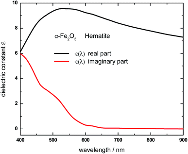 | ||
| Fig. 3 Real (black curve) and imaginary (red curve) part of the wavelength-dependent dielectric constant of Hematite (α-Fe2O3). Data were obtained based on the complex refractive index values reported in ref. 53. | ||
The imaginary part of the dielectric constant, Im(ε(λ)), decreases as the wavelength is increased from 400 to 650 nm, being negligible for larger wavelengths. This trend should be taken into account along with the electric field values, in order to rationalize the variation of the Qabs values with the incident wavelength. Apart from a proportionality factor, the Qabs spectrum for the empty α-Fe2O3 shell (green curve, Fig. 1) follows nearly the same dependence with λ than the Im(ε(λ)) of α-Fe2O3. This observation indicates that the electric field in the empty α-Fe2O3 shell has approximately the same value whatever the incident wavelength, in agreement with panels e–h shown in Fig. 2. On the other hand, considering that for a given wavelength Im(ε(λ)) of α-Fe2O3 has the same value irrespective the Al core is inside it or not, the larger Qabs values for the α-Fe2O3 shell when it wraps the Al core (red curve, Fig. 1) in comparison with the empty α-Fe2O3 shell (green curve, Fig. 1), is attributed to the larger electric field within it (panels a–d, Fig. 2), which in turn is associated to the excitation of the dipole LSPR. These results explicitly show the essence of the plasmon enhanced light absorption in Al@ α-Fe2O3 HNs. Note that, even Im(ε(λ)) of α-Fe2O3 is quite small for λ around 600 nm, the Qabs values for the HN case are significant, due to the fact that at this wavelength the plasmon excitation is on resonance (panel c Fig. 2), leading to the largest electric field enhancement within the shell. This result constitutes a clear example where the dipole moment of the LSPR, spectrally located near to the band edge of a semiconductor material, can be used to extend the effective absorption range of the latter.
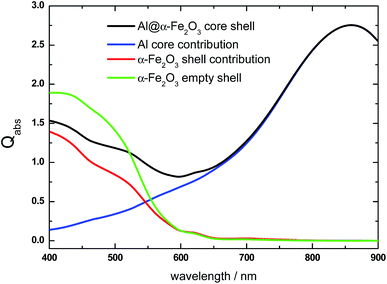
Let us now analyze another representative HN. It is well known that the LSPR redshifts by increasing the aspect ratio of the nanocylinder.62,63 Therefore, by increasing the nanocylinder length, keeping its radius constant, should significantly modify the absorption spectrum. Fig. 4 shows the Qabs spectrum of a longer Al@α-Fe2O3 HN (L = 200 nm, R = 70 nm, r = 50 nm) (black curve) than that shown in the previous example along with the contributions from the Al core and the α-Fe2O3 shell. The overall spectrum shows important differences with respect to that analyzed previously for a shorter HN (black curve, Fig. 1) particularly a noticeable redshift of the absorption peak. The Al core absorption contribution presents a broad absorption peak centered at λ = 850 nm which is assigned to the dipole LSPR excitation that overlaps with the total Qabs spectrum for λ > 650 nm (blue curve, Fig. 4). It is also important to note that the almost 250 nm redshift of the dipole LSPR by increasing 100 nm the nanocylinder length is also favored by the high dielectric constant of the local environment and the contribution to absorption from the α-Fe2O3 shell is relevant for λ < 650 nm (red curve, Fig. 4). Another feature to be remarked is that the Qabs values for the L = 200 nm α-Fe2O3 shell are significantly smaller than the respective values for the L = 100 nm shell (Fig. 1, red curve). At first glance, this effect is directly related with the redshift of the dipole LSPR toward λ > 650 nm, where the α-Fe2O3 shell material does not absorb light. In addition, the Qabs values of the α-Fe2O3 shell in the HN are smaller than the respective values of the α-Fe2O3 shell with empty internal cavity (green curve, Fig. 4).
According to eqn (1), for a given incident wavelength, this difference should be attributed to the differences in the respective |E(ri)|2. Fig. 5 shows 2D plots of the near field enhancement (|E|2/|E0|2) on a plane that contains the E0 and k vectors and cuts the (L = 200 nm, R = 70 nm, r = 50 nm) HN (panels a–d) or the α-Fe2O3 shell with empty internal cavity (panels e–h) in two halves (see Scheme 1), for several incident wavelengths. It can observed that for λ = 460 and λ = 540 nm, the |E|2/|E0|2 values for the α-Fe2O3 shell in the HN (panels a and b, respectively, Fig. 5) are in general smaller than those for the α-Fe2O3 shell with empty internal cavity (panels e and f, respectively, Fig. 5), while for λ = 600 nm the |E|2/|E0|2 values are almost similar for the α-Fe2O3 shell filled with Al (panel c, Fig. 5) or empty (panel g, Fig. 5). These observations explain the differences between the Qabs spectrum for the α-Fe2O3 shell in the HN and the spectrum corresponding to the α-Fe2O3 shell with empty internal cavity, in the spectral region λ ≤ 600 nm (see Fig. 4, red and green curves respectively). For an incident λ = 860 nm, the dipole LSPR is on resonance in the HN and produce large |E|2/|E0|2 values in the α-Fe2O3 shell (panel d, Fig. 5), in clear contrast with the empty shell case (panel h, Fig. 5).
However, although the near field enhancement is relatively high in the HN, the value of Im(ε(λ = 860 nm)) is almost negligible, and consequently Qabs is practically zero. This analysis clearly shows the possibility to modulate the plasmon enhanced light absorption effect in Al@ α-Fe2O3 HNs by controlling the size of the nanostructure. Therefore, regarding light harvesting applications of this type of nanostructured materials, it is relevant to determine the set of L, R and r values that give place to the largest light absorption within the α-Fe2O3 shell.
Dependence of Qabs on the geometrical parameters L, R and r
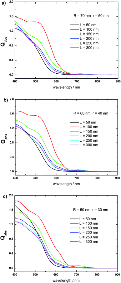
Fig. 6 shows the effect of varying the length L, keeping fixed the R and r values, on the Qabs spectrum of the α-Fe2O3 shell, when it constitutes a Al@α-Fe2O3 HN. Fig. 6a shows this effect for α-Fe2O3 shells with fixed R and r values at 70 and 50 nm, respectively. An increase of L from 50 to 100 nm gives rise to a marked increase of Qabs, whereas as L is further increased from 100 to 300 nm Qabs decreases. Changing significantly R and r to 60 and 40 nm, respectively, produces similar variations in the Qabs spectrum of the α-Fe2O3 shell (Fig. 6b). Qabs increases as L is increased from 50 to 100 nm, and then decreases as L is further increased from 100 to 300 nm. The same trends are qualitatively observed for the α-Fe2O3 shell absorption in the Al@α-Fe2O3 HN with R = 50 nm and r = 30 nm (Fig. 6c). These variations are a consequence of the plasmon enhanced light absorption effect, which in turn is directly associated to the spectral position of the plasmon resonance in the Al core. As the length of the HN is increased from 50 nm to 100 nm, the plasmon resonance wavelength red-shifts gradually from 400 nm to 650 nm, which, in turn, produces an increase in the |E|2 values within the α-Fe2O3 shell. According to eqn (1), this phenomenon leads to an increase in the Qabs values of the α-Fe2O3 shell. Note that in the range 400 nm < λ < 650 nm, the Im(ε(λ)) values of α-Fe2O3 are significantly larger than zero (see Fig. 3, red curve). By increasing the HN length beyond 100 nm, the plasmon resonance wavelength red-shifts toward values larger than 650 nm. As a consequence, enhanced |E|2 values within the α-Fe2O3 shell are produced for λ > 650 nm. However, in this wavelength range, the Im(ε(λ)) of α-Fe2O3 → 0. Therefore, according to eqn (1), the enhanced |E|2 values do not contribute to increase the Qabs values of the α-Fe2O3 shell. These results clearly show that, within the range of R and r values studied, the larger absorption efficiencies for the α-Fe2O3 shell is achieved for Al@α-Fe2O3 HNs with lengths L around 100 nm.Absorbed photon flux in the α-Fe2O3 shell
Photoelectrochemical cells employing photoelectrodes made of α-Fe2O3 offer an inexpensive and clean route for the production of hydrogen from water.21–24 In order to evaluate the effectiveness of Al@α-Fe2O3 HN as component of devices based on light harvesting, for instance as photoelectrodes for water splitting, we have used the Qabs spectra obtained based on DDA simulations to calculate the absorbed photon flux ϕ within the α-Fe2O3 shell according to the following expression:19
 | (2) |
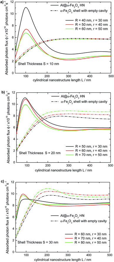
On the contrary, as the LSPR redshifts to wavelengths where Im(ε(λ)) of hematite is nearly zero, typically for λ larger than 650 nm, ϕ decreases with L. Therefore, to achieve large ϕmax values a fine tuning of the geometrical parameters of the HN, L, R and r, is required, in such a way to maximize the integral in eqn (2). For comparison, the dependence of the absorbed photon flux ϕ on the length L of the α-Fe2O3 shell with empty cavity is also shown in Fig. 7 (dotted lines). It can be appreciated that the variation of ϕ with L follows the same general trend: ϕ increases rapidly from L = 50 nm up to L ≈ 200 nm, and then it keeps almost constant as L → 500 nm, being the overall behavior described by a nearly sigmoidal curve. The limiting ϕ value of the α-Fe2O3 shell with empty cavity as L → 500 nm also increases roughly linearly with S. A salient feature in Fig. 7 is the crossing point between the respective curves for the Al@α-Fe2O3 HNs and the α-Fe2O3 shells with empty cavity. This crossing point, whose position on the L axis varies between 120 nm < L < 190 nm depending on the specific R and r values, delimits the length ranges where the absorbed photon flux ϕ is enhanced or reduced within the α-Fe2O3 shell in a given Al@α-Fe2O3 HN in comparison to the α-Fe2O3 shell with empty cavity. For instance, Al@α-Fe2O3 HNs with R = 40, r = 30 nm and L < 185 nm present ϕ values larger than the respective values of the α-Fe2O3 shell with identical dimensions. On the contrary, the relationship between the ϕ values is quite the opposite for L > 185 nm (solid and dashed black curves, Fig. 7a). This observation clearly exemplifies the plasmon enhanced light absorption effect and illustrates, in view of a given application, under which length range it is favorable or not to fill the α-Fe2O3 shell with an Al core.
Effect of the plasmonic metallic core on the absorbed photon flux
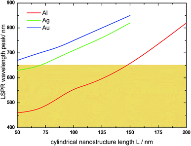
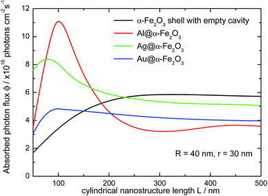
The absorption spectra of Ag@α-Fe2O3 and Au@α-Fe2O3 HNs have also been simulated in order to analyze the effect of the nature of the plasmonic metallic core on the optical response of the HNs (the wavelength dependent complex refractive indexes for Au and Ag were obtained from ref. 64). Fig. 8 shows the variation of the LSPR wavelength peak on the length L of HNs with different core composition (R = 40 nm and r = 30 nm in all cases). In general, whatever the metallic core, a nearly linear dependence between the LSPR wavelength peak and the length L is found. However, for a given L value, the LSPR wavelength peak for Ag (red curve) and Au (green curve) is by far significantly redshifted with respect to the Al LSPR peak (black curve), a phenomena that can be explained in terms of the differences in the respective dielectric constant for each metal. For instance, for L = 100 nm, the LSPR wavelength peaks are located at λ = 555, 710 and 750 nm for Al, Ag and Au, respectively. This example illustrates the following general trend: the LSPR excitation wavelengths for Ag and Au are larger than 650 nm and, therefore, do not overlap within the spectral range in which α-Fe2O3 absorbs, that is, in the spectral range where Im(ε(λ)) > 0 (see Fig. 3, red curve). The spectral range in which α-Fe2O3 absorbs is schematically indicated in Fig. 8 by the colored area. Therefore, these results suggest that Al presents higher capabilities to enhance light absorption in α-Fe2O3 than Ag and Au.Fig. 9 shows the variation of the absorbed photon flux ϕ within the α-Fe2O3 shell with the length L of Al@α-Fe2O3 (red curve), Ag@α-Fe2O3 (green curve) and Au@α-Fe2O3 (blue curve) HNs (R = 40 nm and r = 30 nm, in all cases). The variation of ϕ with L for α-Fe2O3 shells with empty cavity and identical R and r values, is also shown (black curve). The main point to be remarked here is that, for this particular set of R and r values, the largest ϕ is achieved for the HN with Al core and L = 100 nm, whereas the typical plasmonics metals Ag and Au produce significantly smaller ϕ values. This phenomena is directly related to the fact that, for Ag and Au, the plasmon resonances are substantially redshifted in comparison to Al, being as mentioned above located at λ > 650 nm, where the imaginary part of the dielectric constant of α-Fe2O3 is negligible. Therefore, according to eqn (1) and (2), the plasmon enhanced light absorption effect produced by Ag and Au cores is rather poor and lower than that produced by an Al core.
Comparison with infinitely long core shell HNs
To further address the reliability of the theoretical methodology implemented in this work, it is meaningful to contrast the results already presented with those recently reported by Ramadurgam et al.45 In that work, the ϕ values for core@α-Fe2O3 HNs (core = Ag, Si, Si–Ag, Si–Au, Si–Al) have been calculated based on rigorous solutions to the Maxwell's equations using Mie-formalism for L ≫ r (infinite) right circular cylinders. Therefore, the proposed comparison makes sense for Al@α-Fe2O3 HNs with L = 500 nm, where the L ≫ r condition is roughly satisfied according to the length size studied in the current work. Table 1 shows the ϕ values for Al@α-Fe2O3 HNs studied in the present work as well as for Si@α-Fe2O3 and Ag@α-Fe2O3 HNs studied by Ramadurgan et al. The comparison is performed between HNs with the same internal r and external R radius and different core composition (Al, Si and Ag). In addition, the length L is 500 nm for the Al@α-Fe2O3 HNs, whereas for the Si@α-Fe2O3 and Ag@α-Fe2O3 HNs, L > r. The ϕ values for Al@α-Fe2O3 HNs are larger than those for Si@α-Fe2O3, in turn, the ϕ values for Ag@α-Fe2O3 HNs are just slightly larger than those for Al@α-Fe2O3. These relationships highlight the effect of the nature of the core material. Given that the near field enhancements in Ag are larger than in Al nanostructures, it should be expected that Ag cores give rise to much larger ϕ values in comparison to Al cores.33 However, the dipole plasmon resonance for the HNs analyzed in Table 1 (L ≥ 500 nm), which presents larger near field enhancements than higher order modes, is located beyond the visible region of the spectrum.As a consequence, the effect of the nature of the plasmonic core on the ϕ values is attenuated for these L values. For shorter lengths, the dipole LSPR blueshifts toward the visible region, and the near field enhancement generated within the shell produces an enhancement of ϕ (see Fig. 7). Furthermore, this phenomenon should be the main mechanism that explains why the NHs studied in the present work exhibits larger ϕmax values in comparison to those reported previously. For instance, the largest ϕ value (7.4 photons × 1016 cm−2 s−1) reported for Si–Al–α-Fe2O3 HN has been found for Si(40 nm diameter)–Al(50 nm)α-Fe2O3(40 nm) HN, whereas the highest ϕ value found in this work (11.2 photons × 1016 cm−2 s−1) occurs for a Al@α-Fe2O3 HN with R = 40, r = 30 and L = 100 nm. This comparison with the results reported previously for similar HNs further support the consistence of the data presented in this work and emphasizes the relevance of considering not only r and R, that is, the 2D geometry of the HN, but also the length L for an optimum design of HNs potentially useful for harvesting applications.
Conclusions
In this work, the absorption and near field properties of Al@α-Fe2O3 core shell HNs has been theoretically studied by means of Discrete Dipole Approximation simulations, whereas the partial contribution to the absorption spectrum of each component of the HN has been evaluated by implementing a general methodology. The effect of varying the geometrical parameters of the HNs, that is, the length L, the internal r and the external R radius, on the respective absorption spectrum and absorbed photon flux ϕ has been examined systematically. It has been found that, for a given set of r and R values, there exist an L value that gives place to the largest ϕ value. This phenomena results as a compromise between the near enhancements within the α-Fe2O3 shell, which in turn depends on the resonance wavelength of the plasmonic excitations in the Al core, and the value of the wavelength dependent imaginary part of the dielectric constant of α-Fe2O3 (Im(ε(λ))). The plasmon enhanced light absorption phenomena observed in the α-Fe2O3 shell of the Al@α-Fe2O3 HNs studied can be explained in terms of a plasmon-induced energy transfer mechanism based on the near field enhancement. Within the size range studied, the highest ϕ value (11.2 × 10¹⁶ photons per cm2 per s) is reached by the Al@α-Fe2O3 HN with L = 100, R = 40 and r = 30 nm, a ϕ value substantially larger those recently reported for infinitely long HNs with a similar composition. Furthermore, it has been shown that Al leads to greater light absorption in the α-Fe2O3 shell than conventional Ag and Au plasmonic materials, as the dipole plasmon resonance for Ag and Au are spectrally located well beyond the visible regime, where the α-Fe2O3 shell does not absorb. Importantly, in contrast with previous studies, the results presented here demonstrate that the dipole plasmon resonance of the Al core can be tuned into the visible region by adjusting properly the HN length L. Consequently, the HN length L has a crucial role in determining the absorbed photon flux ϕ values, therefore, a smart design of core–shell cylindrical HNs with improved photoactive properties should include the 3D geometry that takes into account the length L of the HN.Acknowledgements
The authors thank CONICET (PIP 112-201101-00430), FONCYT (PICT-2012-2286) and SECyT (UNC) for financial support.References
- S. Banerjee, S. C. Pillai, P. Falaras, K. E. O'Shea, J. A. Byrne and D. D. Dionysiou, New Insights into the Mechanism of Visible Light Photocatalysis, J. Phys. Chem. Lett., 2014, 5, 2543–2554 CrossRef CAS PubMed.
- X. Lang, X. Chen and J. Zhao, Heterogeneous Visible Light Photocatalysis for Selective Organic Transformations, Chem. Soc. Rev., 2014, 43, 473–486 RSC.
- A. I. Hochbaum and P. Yang, Semiconductor Nanowires for Energy Conversion, Chem. Rev., 2010, 110, 527–546 CrossRef CAS PubMed.
- N. Zhou, V. López-Puente, Q. Wang, L. Polavarapu, L. Pastoriza-Santos and Q. Xu, Plasmon-Enhanced Light Harvesting: Applications in Enhanced Photocatalysis, Photodynamic Therapy and Photovoltaics, RSC Adv., 2015, 5, 29076–29097 RSC.
- M. G. Walter, E. L. Warren, J. R. McKone, S. W. Boettcher, Q. Mi, E. A. Santori and N. S. Lewis, Solar Water Splitting Cells, Chem. Rev., 2010, 110, 6446–6473 CrossRef CAS PubMed.
- M. Ni, M. K. H. Leung, D. Y. C. Leung and K. A. Sumathy, Review and Recent Developments in Photocatalytic Water-Splitting Using TiO2 for Hydrogen Production, Renewable Sustainable Energy Rev., 2007, 11, 401–425 CrossRef CAS.
- A. Naldoni, F. Riboni, U. Guler, A. Boltasseva, V. M. Shalaev and A. V. Kildishev, Solar-Powered Plasmon-Enhanced Heterogeneous Catalysis, Nanophotonics, 2016, 5, 112–133 CrossRef CAS.
- K. Ueno, T. Oshikiri and H. Misawa, Plasmon-Induced Water Splitting Using Metallic- Nanoparticle-Loaded Photocatalysts and Photoelectrodes, ChemPhysChem, 2016, 17, 199–215 CrossRef CAS PubMed.
- J. Li, S. K. Cushing, F. Meng, T. R. Senty, A. D. Bristow and N. Wu, Plasmon-Induced Resonance Energy Transfer for Solar Energy Conversion, Nat. Photonics, 2015, 9, 601–608 CrossRef CAS.
- R. Jiang, B. Li, C. Fang and J. Wang, Metal/Semiconductor Hybrid Nanostructures for Plasmon-Enhanced Applications, Adv. Mater., 2014, 26, 5274–5309 CrossRef CAS PubMed.
- A. O. Govorov, H. Zhang and J. K. Gun'ko, Theory of Photoinjection of Hot Plasmonic Carriers from Metal Nanostructures into Semiconductors and Surface Molecules, J. Phys. Chem. C, 2013, 117, 16616–16631 CAS.
- I. Thomann, B. A. Pinaud, Z. Chen, B. M. Clemens, T. F. Jaramillo and M. L. Brongersma, Plasmon Enhanced Solar-to-Fuel Energy Conversion, Nano Lett., 2011, 11, 3440–3446 CrossRef CAS PubMed.
- X. Ma, Y. Dai, L. Yu and B. Huang, Energy Transfer in Plasmonic Photocatalytic Composites, Light: Sci. Appl., 2016, 5, e16017 CrossRef CAS.
- S. K. Cushing and N. Wu, Progress and Perspectives of Plasmon-Enhanced Solar Energy Conversion, J. Phys. Chem. Lett., 2016, 7, 666–675 CrossRef CAS PubMed.
- S. K. Cushing, A. D. Bristowa and N. Wu, Theoretical Maximum Efficiency of Solar Energy Conversion in Plasmonic Metal-Semiconductor Heterojunctions, Phys. Chem. Chem. Phys., 2015, 17, 30013–30022 RSC.
- J. Li and N. Wu, Semiconductor-Based Photocatalysts and Photoelectrochemical Cells for Solar Fuel Generation: A Review, Catal. Sci. Technol., 2015, 5, 1360–1384 CAS.
- R. M. Cornell and U. Schwertmann, The Iron Oxides: Structure, Properties, Reactions, Occurrence and Uses, VCH, Weinheim, 2003 Search PubMed.
- K. Sivula, F. Le Formal and M. Gratzel, Solar Water Splitting: Progress Using hematite (α-Fe2O3) Photoelectrodes, ChemSusChem, 2011, 4, 432–449 CrossRef CAS PubMed.
- A. B. Murphy, P. R. F. Barnes, L. K. Randeniya, I. C. Plumb, I. E. Grey, M. D. Horne and J. A. Glasscock, Efficiency of Solar Water Splitting Using Semiconductor Electrodes, Int. J. Hydrogen Energy, 2006, 31, 1999–2017 CrossRef CAS.
- Y. Qiu, S. Leung, Q. Zhang, B. Hua, Q. Lin, Z. Wei, K. Tsui, Y. Zhang, S. Yang and Z. Fan, Efficient Photoelectrochemical Water Splitting with Ultrathin films of Hematite on Three-Dimensional Nanophotonic Structures, Nano Lett., 2014, 14, 2123–2129 CrossRef CAS PubMed.
- M. E. A. Warwick, K. Kaunisto, D. Barreca, G. Carraro, A. Gasparotto, C. Maccato, E. Bontempi, C. Sada, T. Ruoko, S. Turner and G. Van Tendeloo, Vapor Phase Processing of α-Fe2O3 Photoelectrodes for Water Splitting: An Insight into the Structure/Property Interplay, ACS Appl. Mater. Interfaces, 2015, 7, 8667–8676 CAS.
- M. T. Mayer, C. Du and D. Wang, Hematite/Si Nanowire Dual-Absorber System for Photoelectrochemical Water Splitting at Low Applied Potentials, J. Am. Chem. Soc., 2012, 134, 12406–12409 CrossRef CAS PubMed.
- E. Thimsen, F. Le Formal, M. Grätzel and S. C. Warren, Influence of Plasmonic Au Nanoparticles on the Photoactivity of Fe2O3 Electrodes for Water Splitting, Nano Lett., 2011, 11, 35–43 CrossRef CAS PubMed.
- B. Iandolo, B. Wickman, I. Zorić and A. Hellman, The Rise of Hematite: Origin and Strategies to Reduce the High Onset Potential for the Oxygen Evolution Reaction, J. Mater. Chem. A, 2015, 3, 16896–16912 CAS.
- H. Dotan, O. Kfir, E. Sharlin, O. Blank, M. Gross, I. Dumchin, G. Ankonina and A. Rothschild, Resonant Light Trapping in Ultrathin Films for Water Splitting, Nat. Mater., 2013, 12, 158–164 CrossRef CAS PubMed.
- K. L. Kelly, E. A. Coronado, L. L. Zhao and G. C. Schatz, The Optical Properties of Metal Nanoparticles:
![[thin space (1/6-em)]](https://www.rsc.org/images/entities/char_2009.gif) The Influence of Size, Shape, and Dielectric Environment, J. Phys. Chem. B, 2003, 107, 668–677 CrossRef CAS.
The Influence of Size, Shape, and Dielectric Environment, J. Phys. Chem. B, 2003, 107, 668–677 CrossRef CAS. - A. Verma, A. Srivastav, A. Banerjee, D. Sharma, S. Sharma, U. B. Singh, V. R. Satsangi, R. Shrivastav, D. K. Avasthi and S. Dass, Plasmonic Layer Enhanced Photoelectrochemical Response of Fe2O3 Photoanodes, J. Power Sources, 2016, 315, 152–160 CrossRef CAS.
- J. Wang, S. Pan, M. Chen and D. A. Dixon, Gold Nanorod-Enhanced Light Absorption and Photoelectrochemical Performance of α-Fe2O3 Thin-Film Electrode for Solar Water Splitting, J. Phys. Chem. C, 2013, 117, 22060–22068 CAS.
- H. Gao, C. Liu, H. E. Jeong and P. Yang, Plasmon-Enhanced Photocatalytic Activity of Iron Oxide on Gold Nanopillars, ACS Nano, 2012, 6, 234–240 CrossRef CAS PubMed.
- B. Iandolo, T. J. Antosiewicz, A. Hellman and I. Zorić, On the Mechanism for Nanoplasmonic Enhancement of Photon to Electron Conversion in Nanoparticle Sensitized Hematite Films, Phys. Chem. Chem. Phys., 2013, 15, 4947–4954 RSC.
- P. S. Archana, N. Pachauri, Z. Shan, S. Pan and A. Gupta, Plasmonic Enhancement of Photoactivity by Gold Nanoparticles Embedded in Hematite Films, J. Phys. Chem. C, 2015, 119, 15506–15516 CAS.
- M. W. Knight, N. S. King, L. Liu, H. O. Everitt, P. Nordlander and N. J. Halas, Aluminum for Plasmonics, ACS Nano, 2014, 8, 834–840 CrossRef CAS PubMed.
- M. B. Ross and G. C. Schatz, Radiative Effects in Plasmonic Aluminum and Silver Nanospheres and Nanorods, J. Phys. D: Appl. Phys., 2015, 48, 184004 CrossRef.
- L. Zhou, C. Zhang, M. J. McClain, A. Manjavacas, C. M. Krauter, S. Tian, F. Berg, H. O. Everitt, E. A. Carter, P. Nordlander and N. J. Halas, Aluminum Nanocrystals as a Plasmonic Photocatalyst for Hydrogen Dissociation, Nano Lett., 2016, 16, 1478–1484 CrossRef CAS PubMed.
- D. Gérard and S. K. Gray, Special Issue on Aluminium Plasmonics, J. Phys. D: Appl. Phys., 2015, 48, 180301 CrossRef.
- M. W. Knight, L. Liu, Y. Wang, L. Brown, S. Mukherjee, N. S. King, H. O. Everitt, P. Nordlander and N. J. Halas, Aluminum Plasmonic Nanoantennas, Nano Lett., 2012, 12, 6000–6004 CrossRef CAS PubMed.
- S. K. Jha, Z. Ahmed, M. Agio, Y. Ekinci and J. F. J. Loffler, Deep-UV Surface-Enhanced Resonance Raman Scattering of Adenine on Aluminum Nanoparticle Arrays, J. Am. Chem. Soc., 2012, 134, 1966–1969 CrossRef CAS PubMed.
- B. Tian, X. Zheng, T. J. Kempa, Y. Fang, N. Yu, G. Yu, J. Huang and C. M. Lieber, Coaxial Silicon Nanowires as Solar Cells and Nanoelectronic Power Sources, Nature, 2007, 449, 885–890 CrossRef CAS PubMed.
- C. F. Bohren and D. R. Huffman, Absorption and Scattering of Light by Small Particles, Wiley-Interscience, New York, 1983 Search PubMed.
- Y. Yu, V. E. Ferry, A. P. Alivisatos and L. Cao, Dielectric Core–Shell Optical Antennas for Strong Solar Absorption Enhancement, Nano Lett., 2012, 12, 3674–3681 CrossRef CAS PubMed.
- Y. Zhan, J. Zhao, C. Zhou, M. Alemayehu, Y. Li and Y. Li, Enhanced Photon Absorption of Single Nanowire α-Si Solar Cells Modulated by Silver Core, Opt. Express, 2012, 20, 1506–11516 Search PubMed.
- S. Ramadurgam, T. Lin and C. Yang, Tailoring Optical and Plasmon Resonances in Core-shell and Core-Multishell Nanowires for Visible Range Negative Refraction and Plasmonic Light Harvesting: A Review, J. Mater. Sci. Technol., 2015, 31, 533–541 Search PubMed.
- A. Mirzaei, I. V. Shadrivov, A. E. Miroshnichenko and Y. S. Kivshar, Superabsorption of Light by Multilayer Nanowires, Nanoscale, 2015, 7, 17658–17663 RSC.
- S. A. Mann and E. C. Garnett, Extreme Light Absorption in Thin Semiconductor Films Wrapped around Metal Nanowires, Nano Lett., 2013, 13, 3173–3178 CrossRef CAS PubMed.
- S. Ramadurgam, T. Lin and C. Yang, Aluminum Plasmonics for Enhanced Visible Light Absorption and High Efficiency Water Splitting in Core–Multishell Nanowire Photoelectrodes with Ultrathin Hematite Shells, Nano Lett., 2014, 14, 4517–4522 CrossRef CAS PubMed.
- Z. Chen, T. F. Jaramillo, T. G. Deutsch, A. Shwarscte, A. J. Forman, N. Gaillard, R. Garland, K. Takanabe, C. Heske, M. Sunkara, E. W. McFarland, K. Domen, E. L. Miller, J. A. Turner and H. N. Dinh, Accelerating Materials Development for Photoelectrochemical Hydrogen Production: Standards for Methods, Definitions, and Reporting Protocols, J. Mater. Res., 2010, 25, 3–16 CrossRef CAS.
- E. M. Purcell and C. R. Pennypacker, Scattering and Absorption of Light by Nonspherical Dielectric Grains, Astrophys. J., 1973, 186, 705–714 CrossRef.
- B. T. Draine, The Discrete-Dipole Approximation and its Application to Interstellar Graphite Grains, Astrophys. J., 1988, 333, 848–872 CrossRef CAS.
- B. T. Draine and P. J. Flatau, Discrete Dipole Approximation for Scattering Calculations, J. Opt. Soc. Am., 1994, 11, 1491–1499 CrossRef.
- P. J. Flatau and B. T. Draine, Fast Near-Field Calculations in the Discrete Dipole Aapproximation for Regular Rectilinear Grids, Opt. Express, 2012, 20, 1247–1252 CrossRef CAS PubMed.
- http://www.ddscat.org/.
- B. T. Draine and J. Goodman, Beyond Clausius-Mossotti Wave Propagation on a Polarizable Point Lattice and the Discrete Dipole Approximation, Astrophys. J., 1993, 405, 685–697 CrossRef.
- N. P. Ryde and E. Matijević, Color Effects of Uniform Colloidal Particles of Different Morphologies Packed Into Films, Appl. Opt., 1994, 33, 7275–7281 CrossRef CAS PubMed.
- A. D. Rakić, A. B. Djurišic, J. M. Elazar and M. L. Majewski, Optical Properties of Metallic Films for Vertical-Cavity Optoelectronic Devices, Appl. Opt., 1998, 37, 5271–5283 CrossRef.
- M. Honda, Y. Kumamoto, A. Taguchi, Y. Saito and S. Kawata, Efficient UV Photocatalysis Assisted by Densely Distributed Aluminum Nanoparticles, J. Phys. D: Appl. Phys., 2015, 48, 184006 CrossRef.
- L. Cheng, L. Huang, X. Li, J. Wu, Y. Zhang, J. Wang, L. Cheng, Y. Liu, X. Feng, W. Zhang and Y. Cai, UV Plasmonic Resonance of Aluminum Shallow Pit Arrays, J. Phys. Chem. C, 2015, 119, 14304–14311 CAS.
- M. Honda, Y. Kumamoto, A. Taguchi, Y. Saito and S. Kawata, Plasmon-Enhanced UV Photocatalysis, Appl. Phys. Lett., 2014, 104, 061108 CrossRef.
- J. Martin, M. Kociak, Z. Mahfoud, J. Proust, D. Gérard and J. Plain, High-Resolution Imaging and Spectroscopy of Multipolar Plasmonic Resonances in Aluminum Nanoantennas, Nano Lett., 2014, 14, 5517–5523 CrossRef CAS PubMed.
- S. Ayas, A. E. Topal, A. Cupallari, H. Güner, G. Bakan and A. Dana, Exploiting Native Al2O3 for Multispectral Aluminum Plasmonics, ACS Photonics, 2014, 1, 1313–1321 CrossRef CAS.
- W. P. Hsu and E. Matijevic, Optical Properties of Monodispersed Hematite Hydrosols, Appl. Opt., 1985, 24, 1623–1630 CrossRef CAS PubMed.
- S. S. Wong and L. E. Brus, Narrow Mie Optical Cavity Resonances from Individual 100 nm Hematite Crystallites, J. Phys. Chem. B, 2001, 105, 599–603 CrossRef CAS.
- E. R. Encina and E. A. Coronado, Resonance Conditions for Multipole Plasmon Excitations in Noble Metal Nanorods, J. Phys. Chem. C, 2007, 111, 16796–16801 CAS.
- E. R. Encina, E. M. Perassi and E. A. Coronado, Near Field Enhancement of Multipole Plasmon Resonances in Ag and Au Nanowires, J. Phys. Chem. A, 2009, 113, 4489–4497 CrossRef CAS PubMed.
- Handbook of Optical Constant of Solids, ed. E. D. Palik, Academic Press, New York, 1985 Search PubMed.
| This journal is © The Royal Society of Chemistry 2017 |

