 Open Access Article
Highly oriented lamellar polyaniline films via electrochemical polymerization and post-growth annealing
Suna Fanab,
Renwei Liuab,
Weitao Zheng *a and
Ming Li
 *b
*b
aKey Laboratory of Automobile Materials of MOE, State Key Laboratory of Automotive Simulation and Control, Department of Materials Science, Jilin University, Changchun, Jilin 130000, China. E-mail: wtzheng@jlu.edu.cn
bBeijing National Laboratory for Condensed Matter Physics, Institute of Physics and School of Physical Sciences, University of Chinese Academy of Sciences, Beijing 100190, China. E-mail: mingli@iphy.ac.cn
First published on 16th January 2017
Abstract
A simple and effective way to fabricate highly oriented lamellar PANI films is presented. The lamellae inside the as-grown films lie parallel to the surface of the electrode with a few degrees of misorientation. Upon post-growth annealing at ∼80 °C, they are all re-oriented to almost perfectly parallel to the surface.
Polyaniline (PANI) is one of the most promising conducting polymers and has received enormous attention because of its facile processability, environmental stability, controllable conductivity and low cost.1–3 Many researches have been focused on the synthesis of PANI materials with nanostructures, such as nanoparticles, nanofibers, nanobelts and nanotubes, in order to improve their performances since these materials could combine the advantages of low-dimensionality and conductivity.4–7 PANI with nano-lamellar structure is even more useful in electronic and opto-electronic devices because of its distinctive characteristic conducting pathways and surface interactions.8,9
A few nano-lamellar PANI films have been successfully produced by using template-guided methods, using nano-sheets as templates. For instance, Wang fabricated PANI/manganese oxide nanocomposite through inorganic/organic interface reactions.10 Yang adopted graphene oxide as the template to prepared layered PANI composites.11 Structure-directing molecules were also employed to produce layered PANI.12 Zhang13 and Sniechowski14 found that plasticizing dopants, that is, organic acid containing long alkyl or alkoxy substituents, favor the formation of nano-lamellar PANI. Moreover, polyvinyl pyrrolidone,15 cetyltrimethylammonium bromide16 and various lamellar liquid crystal17–19 were used to direct the growth of flake structure of PANI. Recently, layered PANI nanosheets have been synthesized by self-assembly without the assistance of templates.20,21 However, the nanosheets are disoriented with a surface rough upper to ∼50 nm, which is detrimental to potential applications.22–24 Herein, by using electrochemical polymerization method, we prepared large area layered PANI in which all layers lie parallel to the surface of the electrode.
We prepared PANI films at different potentials and characterized their morphologies by SEM (Fig. 1). The quality of PANI films fabricated by electrochemical polymerization depends on various experimental parameters, such as applied potentials, concentration of aniline and types of dopant. Among them, the applied potential not only controls the oxidation state and degree of doping,25 but also affects the morphology of the products.26 It is seen from Fig. 1 that the PANI films with relatively smooth surfaces can be readily deposited on indium tin oxide (ITO) coated glass at 0.7–0.8 V versus saturated calomel electrode (SCE). When the potential is below 0.7 V, the films are of low quality and cannot even cover the whole substrate. This may be due to the relative slower polymerization rate at low applied potentials. When the potential is higher than 0.8 V, the films become granular and the surfaces become rough. This may result from the side reactions and degradation of PANI at higher applied potential, which is consistent with those reported by Shi and Lapkowski.27,28 Taken together, the low applied potential (0.7–0.8 V) favors the formation of lamellar PANI films.
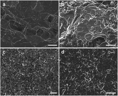 | ||
| Fig. 1 SEM images of PANI films prepared at different potentials. (a) 0.7 V, (b) 0.8 V, (c) 0.85 V, (d) 0.9 V. The scale bars are 10 μm. | ||
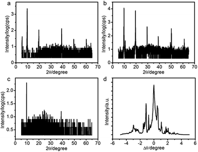
We applied X-ray reflectivity (XRR) to characterize the structures of the PANI films. The XRR patterns of the films fabricated at different potentials are shown in Fig. 2a–c. A series of sharp Bragg peaks are observed in the [001] direction (Fig. 2a and b). The positions of the peaks are indicative of lamellar structures, indicating that the PANI films consist of molecular layers with a stacking period of 9.1 ± 0.1 Å. Consistent with the SEM morphologies, the films fabricated at 0.8 V have the highest diffraction intensities (Fig. 2b). We measured rocking curves around the first Bragg peak to evaluate the overall orientation of lamellae.29 Fig. 2d shows such a rocking curve of the PANI film fabricated at 0.8 V. A few sharp peaks are observed besides a central one. The results suggest that the molecular layers in the PANI film are stacked parallel to the surface of the electrode, but with a certain degree of mosaicity. The samples were all grown at 0.8 V in the following experiments.
The sharp Bragg peaks motivated us to check if the polymer chains in the lamellae are also ordered in the xy-direction. To this end, we performed grazing incident X-ray diffraction (GIXRD) measurement of the films. A very broad peak centered at 22.5° is observed, suggesting that the PANI chains are disordered inside each lamella. This is in agreement with the result of selected area electron diffraction (SAED), which shows a characteristic SAED pattern of the typical amorphous material (Fig. 3b). Therefore, the PANI films we fabricated are composed of stacks of molecular layers that in turn are composed of polymer chains that are randomly organized.
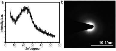 | ||
| Fig. 3 (a) GIXRD pattern and (b) selected area electron diffraction of the PANI film prepared at 0.8 V. | ||
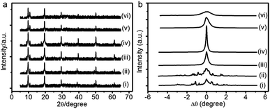
Annealing treatment at certain temperature can activate the mobility of molecules and eliminate the internal defects of samples.30 To test the feasibility of this method for our PANI films, we annealed the as-prepared film at different temperatures using a homemade heating equipment located on a D8-Advance diffractometer, then measured the changes of lamellar structure in situ. Fig. 4 shows the in situ XRR patterns and the rocking curves around the corresponding first Bragg peak of annealed PANI film. When the annealing temperature below 70 °C, no significant difference from the as-prepared film can be observed (see, e.g., curve ii in Fig. 4). Taking a step further to anneal the sample at 75 °C, we found that the small Bragg peaks in the rocking curve merge into a single one although the diffraction pattern does not change much (curve iii in Fig. 4). This implies that the mosaic blocks of PANI film tend to orientate along the same direction. When the annealing temperature is increased to 80 °C (curve iv in Fig. 4), the rocking curve around the first Bragg peak becomes sharp peak with a full-width at half-maximum of only 0.13°. Beyond this optimal annealing temperature, that is 90 °C, the Bragg peak in the rocking curve becomes wide again although it remains as a single one (curve v in Fig. 4). We finally increase the annealing temperature to 95 °C and above, the width of the rocking curve becomes even wider and the intensities of the Bragg peaks become weaker and fade out eventually at the highest temperature our heating equipment can reach.
The above results illustrate that, in order to obtain highly oriented PANI film with low mosaicity, the highest annealing temperature should be less than 90 °C. It is worth noting that up to five Bragg peaks are still observable even for the highest temperature we adopted, suggesting that the lamellar structure of PANI film is stable to some extent.
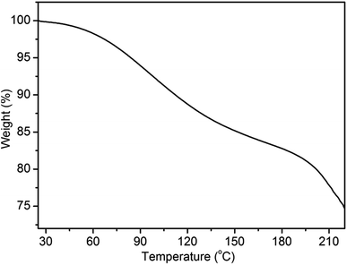
The optimal annealing temperature of the PANI films is 80 °C, which is lower than the glass transition temperature as other reported.31,32 We wondered what caused the re-orientation of the lamellae during thermal annealing. To this end, we performed thermogravimetric analysis (TGA) of the films between 25 and 220 °C under nitrogen atmosphere (Fig. 5). Two stages with rapid weight loss are observed. The first stage starting at ∼60 °C and ending at ∼170 °C can be attributed to the evaporation of water; the second stage starting at ∼190 °C can be assigned to the loss of low-molecular-weight oligomers and dopant.31,33 It is worthy to note that the evaporation of water is the major change occurring during the process of annealing treatment since the study of annealing treatment is performed below 100 °C. Therefore, the change of the lamellar structure of PANI film is attributed to the loss of water. As Matveeva and Rodrigues reported,31,34 there are two forms of water in PANI. The first form of water (hereafter called WF1) can be removed sufficiently through mild treatments, such as drying at 70 °C for 20 min. The second form of water (hereafter called WF2) are absorbed at amine nitrogen with the activation energy of about 13–20 kJ mol−1 and escapes only at elevated temperatures.35 Hence, at lower annealing temperature (≤80 °C), there is only the loss of WF1. This can increase the free volume of the film, allowing PANI chains, which are not in a thermodynamic equilibrium state, to move more easily and to adjust their energy state to the equilibrium state. Therefore, after annealing at low temperature, a more ordered structure is obtained. However, with the increase of annealing temperature, more and more WF2 are evaporated, which can induce the changes of conformational structure, the destruction of crystal lattices, even the irreversible electrochemical inactivation.36,37 This appears to the main reason for the destruction of lamellar structure at high temperature (curve vi in Fig. 4).
Conclusions
In conclusion, lamellar PANI films have been fabricated via electrochemical polymerization with the indium tin oxide (ITO) coated glass as substrate and sulfuric acid as dopant although the mosaicity of as-prepared membrane is relative high. However, the post-annealing treatment can improve the oriented structure of PANI. This study gives a clear guidance for the preparation of highly oriented lamellar PANI films with low mosaicity. The oriented structure could enhance the mobility of charge carriers in PANI by reducing the number of grain boundaries that have poor electronic overlap24 and facilitate further application in versatile electronic devices. In addition, we expect that they could be used as template for fabrication of other oriented functional materials or highly oriented PANI composites for material engineering.Experimental
Lamellar PANI films prepared by electrochemical polymerization
Aniline (99+%) (Alfa Aesar) were distilled prior to use. Sulfuric acid (guaranteed reagent) was used as supplied. Distilled water (18.2 MΩ cm) was produced by a Millipore filter system. ITO coated substrate and polished platinum plate were used as working electrode and counter electrode, respectively. The saturated calomel electrode (SCE) was used as reference electrode. The ITO coated substrates were cleaned by acetone, ethanol and distilled water, respectively. We used a homemade three-electrode cell to electrochemical polymerize PANI on ITO coated substrates, which was performed on a CHI660A electrochemical working station. The electrolyte was 0.5 M H2SO4 solutions containing 0.1 M aniline and was degassed with pure nitrogen to remove oxygen before electrochemical polymerization. The electrochemical polymerization was carried out potentiostatically for 15 min. The applied potentials versus SCE were 0.7, 0.8, 0.85, 0.9 V, respectively. Some of the as-prepared films were dried in an electronic dry cabinet at 25 °C for more than 12 hours. They were used for characterization by SEM, XRR and GIXRD, and for annealing treatment. For TGA and DSC characterizations and further application, the dried films were peeled off from the substrates at ambient temperature and 45 ± 5% RH. Some of the newly prepared films were released into acetone by gentle acetone flush around the substrate with a micropipette and transferred onto lacey-carbon-coated grids for SAED characterization.Annealing treatment of PANI films
The homemade heating equipment located on a D8-Advance diffractometer was used to heat PANI films under the heating rate of 1 °C min−1. Note that the film was kept at target temperature for 1 h, then in situ studied the changes of lamellar structure during the heating process through X-ray diffractometer. Subsequently, the sample was refrigerated to room temperature slowly under the rate of 2 °C min−1. After XRR characterization, the sample was annealed at different temperature repeatedly.Morphology and structure characterization
The surface morphology of PANI films was imaged by a Hitachi S-4800 SEM. The lamellar structure was characterized by a Bruker D8-Advance diffractometer. The X-ray reflectivity was measured by performing a theta–2theta scan, collecting diffraction peaks along the [001] direction. The rocking curve around the (001) peak was obtained by setting the 2theta angle at that of (001) and rocking the sample. SAED was performed on the TEM characterization with a JEOL JEM-100CX II electron microscope operated at 200 kV. The ordering in the xy-direction was characterized by GIXRD measurement on a 5-circle Huber diffractometer on the 4W1A beam line at the Beijing Synchrotron Radiation Facility (BSRF). The thermal stability of PANI films was studied by TGA and DSC. The TGA was performed on TA Instruments thermal analyzer model SDTQ600 under nitrogen atmosphere. The samples were heated from 25 to 220 °C at a heating rate of 10 °C min−1. The sample was encapsulated in an aluminum pan and heated at a heating rate of 10 °C min−1 in a 2920 DSC (TA Instruments) under nitrogen atmosphere.Acknowledgements
This work was supported by the National Natural Science Foundation of China (Grant No. 61275192, 51372095, 91323304) and by the Key Research Program of Frontier Sciences, CAS (Grant No. QYZDJ-SSW-SYS014) (to M. L.).Notes and references
- G. Ćirić-Marjanović, Synth. Met., 2013, 177, 1–47 CrossRef.
- J. Stejskal, I. Sapurina and M. Trchová, Prog. Polym. Sci., 2010, 35, 1420–1481 CrossRef CAS.
- N. R. Chiou, C. Lu, J. Guan, L. J. Lee and A. J. Epstein, Nat. Nanotechnol., 2007, 2, 354–357 CrossRef CAS PubMed.
- D. Pahovnik, E. Žagar, K. Kogej, J. Vohlídal and M. Žigon, Eur. Polym. J., 2013, 49, 1381–1390 CrossRef CAS.
- J. Han, J. Dai, C. Q. Zhou and R. Guo, Polym. Chem., 2013, 4, 313–321 RSC.
- H. B. Zhang, J. X. Wang, Z. Wang, F. B. Zhang and S. C. Wang, Synth. Met., 2009, 159, 277–281 CrossRef CAS.
- G. R. Li, Z. P. Feng, J. H. Zhong, Z. L. Wang and Y. X. Tong, Macromolecules, 2010, 43, 2178–2183 CrossRef CAS.
- L. Shi, X. D. Wu, L. D. Lu, X. J. Yang and X. Wang, Synth. Met., 2010, 160, 989–995 CrossRef CAS.
- L. L. Wang, Z. Lou, R. Wang, T. Fei and T. Zhang, J. Mater. Chem., 2012, 22, 12453 RSC.
- Y. G. Wang, W. Wu, L. Cheng, P. He, C. X. Wang and Y. Y. Xia, Adv. Mater., 2008, 20, 2166–2170 CrossRef CAS.
- N. L. Yang, J. Zhai, M. X. Wan, D. Wang and L. Jiang, Synth. Met., 2010, 160, 1617–1622 CrossRef CAS.
- B. Dufour, P. Rannou, D. Djurado, H. Janeczek, M. Zagorska, A. de Geyer, J. P. Travers and A. Pron, Chem. Mater., 2003, 15, 1587–1592 CrossRef CAS.
- H. M. Zhang, X. H. Wang, J. Li, Z. S. Mo and F. S. Wang, Polymer, 2009, 50, 2674–2679 CrossRef CAS.
- M. Sniechowski, D. Djurado, B. Dufour, P. Rannou, A. Pron and W. Luzny, Synth. Met., 2004, 143, 163–169 CrossRef CAS.
- H. S. Fan, H. Wang, X. L. Yu, N. Zhao, X. L. Zhang and J. Xu, Mater. Lett., 2012, 71, 70–73 CrossRef CAS.
- X. X. Xu, H. Bao, P. Wang, S. L. Jin and Z. M. Gu, Polym. Int., 2012, 61, 768–773 Search PubMed.
- G. P. Song, J. Han, J. Bo and R. Guo, J. Mater. Sci., 2008, 44, 715–720 CrossRef.
- D. Pahovnik, E. Žagar, J. Vohlidal and M. Žigon, Synth. Met., 2010, 160, 1761–1766 CrossRef CAS.
- L. Shi, X. D. Wu, L. D. Lu, X. J. Yang and X. Wang, J. Phys. Chem. B, 2009, 113, 2725–2733 CrossRef CAS PubMed.
- Q. Tang, J. Wu, X. Sun, Q. Li, J. Lin and M. Huang, Chem. Commun., 2009, 16, 2166–2167 RSC.
- H. K. Seo, S. Ameen, M. S. Akhtar and H. S. Shin, Talanta, 2013, 104, 219–227 CrossRef CAS PubMed.
- H. D. Yu, Z. P. Zhang, M. Y. Han, X. T. Hao and F. R. Zhu, J. Am. Chem. Soc., 2005, 127, 2378–2379 CrossRef CAS PubMed.
- D. Wang, P. Song, C. Liu, W. Wu and S. Fan, Nanotechnology, 2008, 19, 075609 CrossRef PubMed.
- K. R. Joseph, M. D. Mcgehee and M. F. Toney, Nat. Mater., 2006, 5, 222–228 CrossRef.
- S. Bhadra, N. K. Singha, S. Chattopadhyay and D. Khastgir, J. Polym. Sci., Part B: Polym. Phys., 2007, 45, 2046–2059 CrossRef CAS.
- Q. Qin, J. Tao and Y. Yang, Synth. Met., 2010, 160, 1167–1172 CrossRef CAS.
- G. Shi, S. Jin, G. Xue and C. Li, Science, 1995, 267, 994–996 CrossRef CAS PubMed.
- M. Lapkowski, Synth. Met., 1990, 35, 169–182 CrossRef CAS.
- L. L. Xing, B. Yuan, S. X. Hu, Y. D. Zhang, Y. Lu, Z. H. Mai and M. Li, J. Phys. Chem. C, 2008, 112, 3800–3804 CAS.
- Z. T. Ding, R. Y. Bao, B. Zhao, J. Yan, Z. Y. Liu and M. B. Yang, J. Appl. Polym. Sci., 2013, 130, 1659–1665 CrossRef CAS.
- P. C. Rodrigues, G. P. de Souza, J. D. D. M. Neto and L. Akcelrud, Polymer, 2002, 43, 5493–5499 CrossRef CAS.
- M. J. R. Cardoso, M. F. S. Lima and D. M. Lenz, Mater. Res., 2007, 10, 425–429 CAS.
- M. V. Kulkarni and A. K. Viswanath, Eur. Polym. J., 2004, 40, 379–384 CrossRef CAS.
- E. S. Matvccva, Synth. Met., 1996, 79, 127–139 CrossRef.
- E. S. Matveeva, R. D. Calleja and V. P. Parkhutik, Synth. Met., 1995, 72, 105–110 CrossRef CAS.
- S. K. Mondal and N. Munichandraiah, J. Electroanal. Chem., 2006, 595, 78–86 CrossRef CAS.
- A. Boyle, J. F. Penneau, E. Genies and C. Riekel, J. Polym. Sci., Part B: Polym. Phys., 1992, 30, 265–274 CrossRef CAS.
| This journal is © The Royal Society of Chemistry 2017 |

