 Open Access Article
Creative Commons Attribution 3.0 Unported Licence
Sc promoted and aerogel confined Ni catalysts for coking-resistant dry reforming of methane†
Xiaoyuan Zhao,
Yang Cao,
Hongrui Li,
Jianping Zhang,
Liyi Shi and
Dengsong Zhang *
*
Research Center of Nano Science and Technology, Department of Chemistry, Shanghai University, Shanghai 200444, China. E-mail: dszhang@shu.edu.cn; Tel: +86-21-66137152
First published on 17th January 2017
Abstract
In this study, Sc promoted and aerogel confined Ni catalysts were synthesized via a facile method. The catalyst thus prepared was completely characterized and tested under conditions for the dry reforming of methane (DRM). As compared to Ni-based catalysts, all Sc promoted catalysts exhibited excellent catalytic stability as the addition of Sc strengthened the interaction between the γ-Al2O3 support and Ni species, increased the reactive oxygen species and basic sites on the catalyst surface. Moreover, a uniform distribution of Ni and Sc species can be achieved by the unique fabrication pathway, thereby resulting in the increase of the activities and coking-resistance of Ni-based catalysts for the DRM reaction. Additionally, at high reaction temperature, the stable mesostructure of the Al2O3 aerogel restricted the motion of Ni nanoparticles, limiting the sintering of Ni nanoparticles. Therefore, the Sc decorated and aerogel confined Ni-based catalysts exhibited excellent catalytic performance, good coking resistance and superior stability.
1. Introduction
During the past decades, the dry (CO2) reforming of methane (DRM, CH4 + CO2 → CO + H2) has attracted significant attention from both environmental and industrial perspectives.1–4 With respect to the environment, the DRM reaction provided a method for effectively consuming greenhouse gases (CH4 and CO2). From the industrial aspect, the DRM reaction provides a favorable hydrocarbon ratio for synthesis gas (CO and H2), which could be converted into useful products by the Fischer–Tropsch reaction.5–7 The catalysts used for reactions can be classified noble-metal- and transition-metal-based catalysts. Although the noble-metal-based catalysts exhibit excellent catalytic performance, their applications are limited because of their high cost and low availability.8,9 Transition-metal based catalysts, particularly nickel-based catalysts, have been intensively studied, attributed to their cost efficiency, abundant reserves, and relatively high activity for C–H and C–C bond cleavage.10–18 Unfortunately, under harsh reaction conditions, the agglomeration of nickel nanoparticles and coking are major drawbacks resulting in catalyst deactivation.19,20 Moreover, the large metal nanoparticles formed can decrease the active sites and surface area.21 The deposition of carbon blocks the metal surface via the CH4 decomposition and Boudouard reaction.22 Their reaction equations were 2CO → C + CO2 and CH4 → C + H2, respectively. Therefore, preventing the sintering of the Ni nanoparticles, restraining the generation of carbon, and decreasing the effect of carbon deposition on Ni-based catalysts are crucial for the industrial progress of DRM.Thus far, many methods have been investigated for preventing the formation of large Ni nanoparticles or restraining carbon generation by our group as well as other groups, such as limiting the sintering of Ni nanoparticles and improving the properties of the support.23–26 For limiting the sintering and increasing the dispersion of Ni nanoparticles, the design of catalysts having a special structure, such as core–shell and mesoporous structures, has attracted significant attention.27 Typically, Al2O3 and SiO2 are chosen as carriers for catalysts because they exhibit good thermal stability.28–31 For example, Song et al. have synthesized Ni@SiO2 yolk–shell nanoreactor catalysts, which exhibit good stability at 700 °C.32 Ni deposited on various stable mesoporous supports have also been successively prepared and employed as DRM catalysts.33–37 In our previous study, a mesoporous-silica-encapsulated NiMgAl-LDO and mesoporous silica SBA-15-confined Ni nanoparticle catalysts have been successfully synthesized and tested for DRM.12,24 Furthermore, the use of catalysts with basic alkaline and rare earth metals typically result in the enhancement of catalytic activity and suppression of coke deposition.31 For example, the doping of Zr into Ni-MCM-41 significantly promotes the dispersion of Ni and extends the stability of Ni nanoparticles for DRM, attributed to the anchoring effect of ZrO2.33 Coincidentally, the coating MgO of layer on SiO2 surface enhances the interaction between the γ-Al2O3 support and Ni via the formation of the Ni–Mg mixed oxides and Mg2SiO4 species.38 These interactions are beneficial for preventing the sintering of Ni-based metallic species. A mesoporous Ni–Ce–Al catalyst with increased life time and catalytic activity has been synthesized.39 CeO2 is used as a promoter owing to its excellent redox property, as well as its capacity for inducing strong interactions between the active metal and support.40–42 The Sc-promoted Co/TiO2 catalysts system have been developed and evaluated for DRM. The doping of scandium improves the alkalinity and enhances the metal–support interaction in the catalyst.43 However, synthesizing a DRM catalyst with high activity and stability is still a challenge.
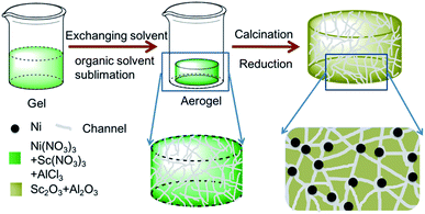
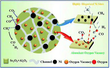
In this work, Sc promoted and aerogel confined Ni catalysts was prepared by a facile method (Scheme 1). First, the precursors (Ni(NO3)3·6H2O, AlCl3·6H2O and Sc(NO3)3·6H2O) are dissolved in a mixture of ethanol and deionized water, followed by the addition of 1,2-epoxypropane to form the hydrogel. Second, the hydrogel is transformed into an aerogel by solvent exchange and organic solvent sublimation.44 Finally, Sc decorated and aerogel confined Ni catalysts are obtained by calcination and reduction. The incorporation of Sc could increase the reactive oxygen and basicity on catalyst, which could suppress coke deposition, and strengthen the interaction between the γ-Al2O3 support and Ni nanoparticles. Moreover, Ni–O–Al structure can be constructed in the gel after calcination, therefor resulting in the uniformly dispersion of Ni and Sc species.45–48 Additionally, the stable architecture could restrict the motion of Ni nanoparticles under high reaction temperature, thereby limiting the sintering of Ni nanoparticles. In our expectation, the catalysts synthesized by the unique fabrication pathway should enjoy the favorable DRM activities and coking-resistance. Finally, the texture properties, DRM activity, stability, and anti-coke ability of the catalyst were carefully investigated.
2. Experimental section
2.1 Catalysts preparation
All chemicals were used without any further purification, and all chemicals were produced by Sinopharm Chemical Reagent Company, except for alumina and scandium nitrate: deionized water (H2O), aluminum chloride (AlCl3·6H2O, 99%), 1,2-epoxypropane (C3H6O, 99%), tert-butanol (C4H10O, 99%), nickel nitrate (Ni(NO3)3·6H2O, 98%), spherical alumina (γ-Al2O3, Shanghai Emperor Yang Co. Ltd), scandium nitrate (Sc(NO3)3·6H2O, 99%, Shanghai Emperor Yang Co. Ltd). Deionized water was used throughout the experiment.A typical synthesis of the catalyst is as follows: AlCl3·6H2O (2.96 g), Ni(NO3)3·6H2O (0.35 g), and Sc(NO3)3·6H2O (0.053 g) were dissolved in 20 mL of a 50/50 v/v mixture of water and ethanol. Propylene oxide (8.0 g) was added to the clear solution, followed by vigorous stirring 10 min. The clear solution was stirred for approximately 180 min until the occurrence of gelation, affording green and transparent monoliths. Before drying at 50 °C under a vacuum of 80–100 kPa, the acquired wet gel were washed in 50%, 80%, and 100% of the exchanging solvent tertiary butyl alcohol/ethanol (v/v) for 1 day at 50 °C. Under low vacuum, the solvent in the wet gel was easily evaporated, thereby affording aerogels. The aerogel was calcined at 600 °C with a ramping rate of 1 °C min−1 in air for 180 min. The NiSc/Al2O3-A catalyst was obtained by reducing the final sample in the gas mixture of 10% H2/N2 (flow rate = 40 mL min−1) at 900 °C for 1 h, which was denoted as NiSc/Al2O3-A catalysts.
For comparison, the catalyst was synthesized by a method similar to that employed for synthesizing the NiSc/Al2O3-A catalyst, except in the absence of Sc(NO3)3·6H2O, denoted as Ni/Al2O3-A; catalysts were prepared by impregnation method, denoted as Ni/Al2O3-I and NiSc/Al2O3-I, respectively. The details of preparation are provided in ESI.†
2.2 Catalyst characterization
TEM observation was employed on JEM-2100F system for the characterization of the detailed morphology of catalysts. The microscope was also equipped with EDS detector for elemental analysis. X-ray diffraction (XRD) analysis were performed on a Rigaku D/MAX-RB XRD apparatus containing Cu Kα radiation (40 kV, 30 20 mA) and a secondary-beam graphite monochromator. Autosorb-iQ2 apparatus was used to determine the specific surface areas and porous properties of the catalysts. The H2-TPR measurements were conducted in 5 mm quartz tube reactor equipped with a TCD. First, the catalysts (80 mg) were pre-treated at 300 °C for 0.5 h in the gas flow of high-purity N2. When the catalysts were allowed to cooled down naturally to room temperature, a flow of 10% H2 in N2 (40 mL min−1) was introduced, and the programming temperature was raised from room temperature to 800 °C at a rate of 10 °C min−1. Measurements of CO2 temperature programmed desorption (CO2-TPD) were conducted in a quartz tube reactor using 150 mg of catalyst and treated at 300 °C in He (30 mL min−1) for half hour. After cooling to 50 °C, a flow of CO2 (50 mL min−1) was introduced for 1 h, and the programming temperature was raised from room temperature to 800 °C at a rate of 10 °C min−1. O2-TPO measurement was conducted in the similar condition as H2-TPR except the amount of tested sample (50 mg) and components of the gas mixture (10% O2 in N2) was used. The XPS analysis was conducted on an RBD-upgraded PHI-5000CESCA with Mg Kα radiation. Binding energies were corrected by the standard location of carbon (284.6 eV). Hydrogen chemisorption was estimated using an Autosorb-1-C (Quantachrome) system. First, the catalyst was dehydrate under a He atmosphere at 250 °C for 2 h; second, they were reduced in purified H2 at 900 °C at a heating rate of 10 °C min−1. For chemisorption measurement, the residual H2 were emitted with helium at the same temperature for 2 h and then cooled down to 40 °C in vacuum. Thermogravimetric analysis (TG, 30–1000 °C, ramping rate = 10 °C min−1) was employed for investigating the coke amount formed during the catalytic process. A visible Raman spectrum (Raman) was recorded on an HR Evolution Raman spectrometer (Horiba JobinYvon Ltd, Japan). The compositions of the catalysts were estimated by ICP analysis using a PERKINK 7300 DV apparatus.2.3 DRM catalysts performance tests
The fixed-bed reactor was employed for the DRM reaction. Before the DRM reaction, 0.15 g of catalysts were sieved and inserted into the quartz tube (id = 8 mm). The composition of the reactant gas was set to CH4![[thin space (1/6-em)]](https://www.rsc.org/images/entities/char_2009.gif) :
:![[thin space (1/6-em)]](https://www.rsc.org/images/entities/char_2009.gif) CO2 = 1
CO2 = 1![[thin space (1/6-em)]](https://www.rsc.org/images/entities/char_2009.gif) :
:![[thin space (1/6-em)]](https://www.rsc.org/images/entities/char_2009.gif) 1, while the flow rate was controlled to 15 mL min−1. The DRM activity was estimated in the temperature range from 450 °C to 800 °C with a ramping rate of 10 °C min−1. The outlet gas was cooled in water cooling system and analyzed by a TDX-01 packed column. Stability tests were also conducted at 750 °C for 30 h.
1, while the flow rate was controlled to 15 mL min−1. The DRM activity was estimated in the temperature range from 450 °C to 800 °C with a ramping rate of 10 °C min−1. The outlet gas was cooled in water cooling system and analyzed by a TDX-01 packed column. Stability tests were also conducted at 750 °C for 30 h.
3. Results and discussion
3.1 Characteristics of the fresh catalysts
Fig. 1 shows the TEM image, HRTEM image and EDS mapping of the fresh NiSc/Al2O3-A catalyst. Ni nanoparticles were evenly distributed over the Al2O3 aerogel support and exhibited a uniform size distribution, with an average particle size of 13 nm (Fig. 1a). A mesostructure was also clearly observed. In contrast, the fresh Ni/Al2O3-A catalyst also exhibited a mesostructure, indicating that the incorporated Sc does not affect the formation of the catalyst mesostructure (Fig. S1a†). However, the catalysts prepared by impregnation (Ni/Al2O3-I and NiSc/Al2O3-I) did not exhibit such a stable mesoporous structure (Fig. S1b and S1c,† respectively). A mesostructure was formed by the sublimation of organic solvent under low vacuum conditions at 50 °C, which was considerably beneficial to form small Ni nanoparticles. The Ni nanoparticles were uniformly distributed on the porous support, which could limit sintering under harsh reaction conditions, caused by the confinement effect attributed to the stable mesoporous wall of the Al2O3 support. Besides, the diffusion of reactant gas from the stable mesoporous shell of the aerogel structure occurred in a facile manner, which should be beneficial for the DRM reaction. As can be observed in the HRTEM image, the NiSc/Al2O3-A catalyst exhibited micromorphology. The lattice spacing was 0.205 nm (Fig. 1b) that can be indexed to the (111) plane, which was favorable for the DRM reaction. The EDX spectra (Fig. 1c) demonstrated that Ni, Al, and Sc were homogeneously dispersed in the aerogel structure, caused by the formation of Ni–O–Al in the catalysts by a sol–gel method. These results indicate that the Ni nanoparticles are easily immobilized into porous framework of the Al2O3 aerogel.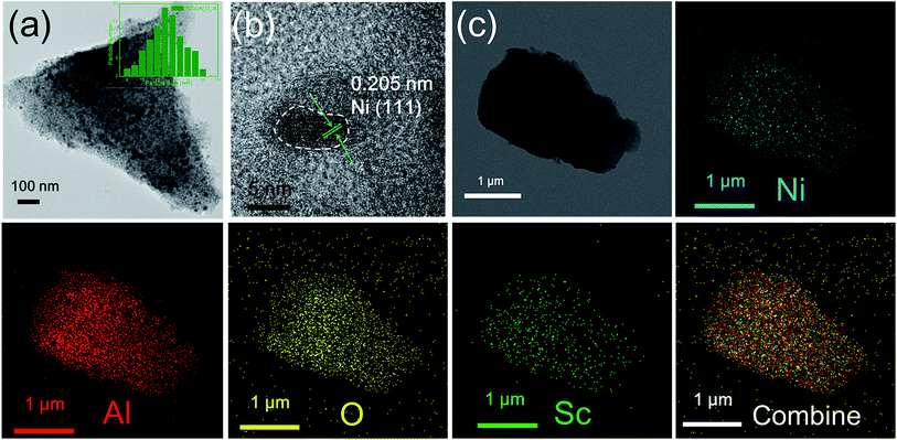 | ||
| Fig. 1 (a) TEM image (inset: the size distributions of Ni NPs); (b) HRTEM image and (c) EDX mapping of the fresh NiSc/Al2O3-A catalyst. | ||
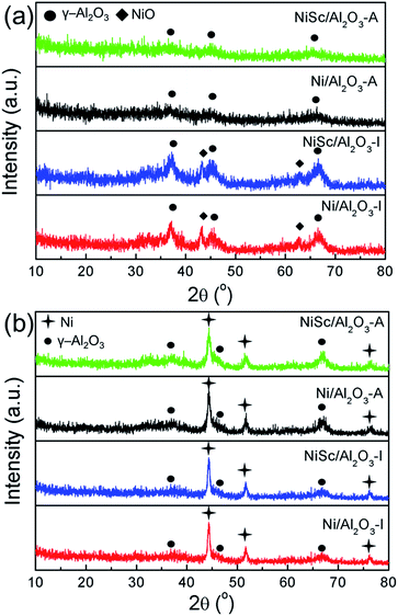
Fig. 2a shows the XRD patterns of various calcined catalysts. All catalysts exhibited characteristic peaks for γ-Al2O3 (JCPDS no. 10-0425). The NiSc/Al2O3-I and Ni/Al2O3-I catalysts exhibited NiO peaks (JCPDS no. 47-1049). However, the NiSc/Al2O3-A and Ni/Al2O3-A catalysts did not exhibit any diffraction peaks related to NiO. This result indicates that NiO was homogeneously dispersed over the meso-Al2O3 support. In addition, it is commonly accepted that the degree of crystallinity of metal is higher than that of metallic oxide, and thus the Ni species can still be observed over the reduced catalysts. Fig. 2b shows the XRD patterns of reduced catalysts. As compared to the XRD of calcined catalysts, that of all catalysts exhibited characteristic diffraction peak for γ-Al2O3 (JCPDS no. 10-0425) and Ni (JCPDS no. 04-0850) after reduction. The diffraction peaks of Ni attributed to three different crystal planes ((111), (200), and (222)), respectively. It was confined that the incorporation of Sc did not affect the crystal structure of both aerogel and impregnated catalysts. For the NiSc/Al2O3-A catalyst, the particle sizes of Ni nanoparticles were 13.75 nm, which was calculated from the (111) peak using the Scherrer equation which was consistent with Fig. 1a.
Fig. 3 shows the N2-adsorption isotherms and pore size distributions of the catalysts after reduction. A typical IV curve with an H2-shaped hysteresis loop was observed in the isotherms of the NiSc/Al2O3-A and Ni/Al2O3-A catalysts, indicating that stable mesoporous materials exhibit a characteristic ink-bottle shape. As can be expected, Ni nanoparticles could be formed and anchored in the porous framework during the reduction process. Table 1 lists the textural properties of catalysts. The pore sizes of the fresh NiSc/Al2O3-A and Ni/Al2O3-A catalysts were 7.9 and 8.1 nm, respectively. This result implies that the incorporated Sc does not affect catalyst structure, which was well consistent with TEM observation. As compared with the aerogel catalysts, the catalysts prepared by impregnation exhibited completely different adsorption and desorption isotherms. A typical type III curve with an H4-shaped hysteresis loop was observed in the isotherms of the Ni/Al2O3-I and NiSc/Al2O3-I catalysts, indicating that the interaction between nitrogen and materials is very weak. The capillary condensation step for the P/P0 values between 0.85 and 1.00 indicated that the pores in the material are attributed to the stacking of particles. Besides, the surface areas of the NiSc/Al2O3-A and Ni/Al2O3-A catalysts were 233 and 224 m2 g−1, respectively, greater than those of the Ni/Al2O3-I and NiSc/Al2O3-I catalysts. From the TEM images, N2-adsorption isotherms and pore size distributions, we supposed that the migration of Ni particles can be restricted by the matrix of aerogel. Actually, the surrounded mesoporous channels of aerogel provide the reactants with the routes to the surface of Ni. The abundant mesoporous channels may form around the Ni particles by the sublimation of the organic solvent, thus, the stable mesoporous structure can inhibit the migration of Ni species.
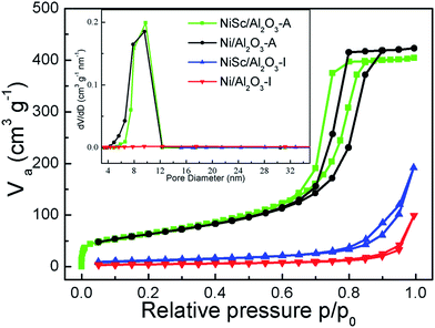 | ||
| Fig. 3 Nitrogen adsorption–desorption isotherms; (inset) pore size distributions of various catalysts. | ||
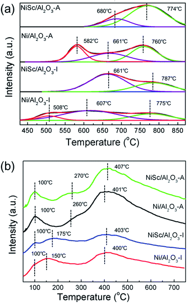
Fig. 4a shows the H2-TPR curves of all calcined catalysts. For the H2-TPR tests, all the samples were reduced under the H2 atmosphere at 900 °C for 1 h to ensure all the Ni species can be reduced from the catalysts, the reduction temperature is responsible for the different metal–support interaction. For the Ni/Al2O3-I catalyst, three major reduction peaks were observed at 508, 607, and 775 °C, respectively. The NiSc/Al2O3-I catalyst exhibited two main reduction peaks at 661 and 787 °C, respectively. On the other hand, the Ni/Al2O3-A catalyst exhibited three main reduction peaks at 582, 661, and 760 °C. The NiSc/Al2O3-A catalyst exhibited two H2 consumption peaks at 680 and 774 °C, respectively.36 For all catalysts, the H2 consumption peaks below 690 °C can be assigned to reduction of Ni2+ into Ni0, exhibiting weak interaction with the γ-Al2O3 substrate.13 The peaks greater than 690 °C were attributed to the insertion of Ni2+ into the Al2O3 lattice forming the NiAlOx phases, which was in intimate contact with the support.25,49 As compared to the Ni/Al2O3-I catalyst, the NiSc/Al2O3-I catalyst did not exhibit a reduction peak at 513 °C, and the reduction peaks of the NiSc/Al2O3-I catalyst shifted toward high temperature after the addition of Sc. This result suggested that the doping of Sc lead to the strengthening of the interaction between Ni and Al2O3, which could prevent the sintering of Ni species. As compared with that of the Ni/Al2O3-A catalyst, the H2 consumption peak of the NiSc/Al2O3-A catalyst at 582 °C disappeared, caused by the incorporation of Sc. The addition of Sc led to the shift of the peak for the NiSc/Al2O3-A catalyst to high temperature. This result also indicated that the similar promotion effect of Sc in the aerogel catalysts. In addition, the existence of the NiAlOx species over the aerogel catalysts may be responsible for the improved sintering resistance to improve the catalytic performance. Therefore, it is important to illustrate the percentage of the NiAlOx species occupying the total amount of Ni presented in catalysts. We compared the area percentage of reduction peak of the NiAlOx species occupying the total area and the percentage are summarized in Table 3, which can explain the existence of the number of NiAlOx species. The NiSc/Al2O3-A catalyst exhibited the highest percentage of NiAlOx species, suggesting the stronger metal–support interaction in the NiSc/Al2O3-A catalyst. As compared to the Ni/Al2O3-I catalyst, the Ni/Al2O3-A catalyst exhibited the higher percentage of NiAlOx species. By the sol–gel method, more Ni species formed NiAlOx with the γ-Al2O3 support, resulting in a highly strong interaction. The interaction between support and metal is an important aspect which could prevent catalyst deactivation effectively during the DRM reaction.
Fig. 4b demonstrated the CO2-TPD profiles of various catalysts after reduction. There were three CO2 desorption peaks were observed in all catalysts. The peaks at 100 °C are attributed to the physical adsorption of CO2.50 Moreover, the CO2 desorption peaks ranging from 150 to 280 °C could be correspond to the moderate basic sites. Meanwhile, the peaks around 400 °C were associated with the strong basic sites.51 The peak area at 100 °C for the NiSc/Al2O3-A and Ni/Al2O3-A catalysts was larger than that of the NiSc/Al2O3-I and Ni/Al2O3-I catalysts, which suggested that NiSc/Al2O3-A and Ni/Al2O3-A catalysts contain more physical adsorption of CO2 due to the larger specific surface area. Moreover, the peak area of NiSc/Al2O3-I and NiSc/Al2O3-A were larger than those of Ni/Al2O3-I and Ni/Al2O3-A, which suggested the Sc doping could promote the CO2 adsorption capacity.43 In addition, the integration of peak area could also reflect the dramatic increase of the surface basic sites aroused by the aerogel structure. Table 2 further demonstrated the basic sites distribution and the relative contents.
| Catalysts | Basic sites distribution | ||
|---|---|---|---|
| Strong basic sites | Moderate basic sites | Total | |
| NiSc/Al2O3-A | 302.6 | 26.4 | 329.0 |
| Ni/Al2O3-A | 281.3 | 6.9 | 288.2 |
| NiSc/Al2O3-I | 139.5 | 58.2 | 197.7 |
| Ni/Al2O3-I | 127.8 | 60.2 | 188.0 |
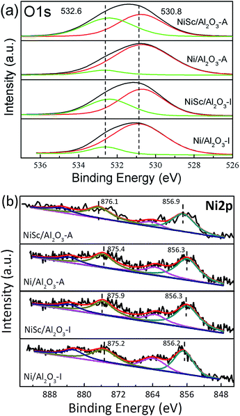
Fig. 5a shows the XPS profiles of the catalysts, which provides information about chemical states of the elements on the catalyst surface. The O 1s spectra of the catalysts were fitted with two peaks: the peak located at 530.8 eV related to the lattice oxygen species (Oα) and the other peak located at 532.6 eV could be assigned to the chemisorbed oxygen species (Oβ). The Oβ peak corresponds to the adsorbed oxygen from C–O in CO32− and –OH in water.49 The formation of CO32− species are mainly due to the existence of oxygen vacancies. The content of oxygen vacancies could be estimated from the XPS relative percentage of the adsorbed oxygen which is always considered as the active oxygen species.39 Table 3 further illustrated the ratio of Oβ. It can be noticed that the NiSc/Al2O3-A catalyst exhibited the highest proportion of adsorbed oxygen species, which may suggest that the NiSc/Al2O3-A catalyst contains more surface active oxygen species than the others. In addition, the content of surface active oxygen species on the NiSc/Al2O3-I catalyst was higher than those on the Ni/Al2O3-I and Ni/Al2O3-A catalysts. According to the above results, the incorporation of Sc in the catalysts contributed to the improvement of surface active oxygen.53 Especially, surface active oxygen species could react with the deposited carbon and suppress the coke formation, leading to the excellent catalytic stability. The Ni 2p spectra can be fitted into four peaks attributed to Ni 2p3/2 peak ranged at 856.2–856.9 eV and Ni 2p1/2 peak ranged at 875.2–876.1 eV as well as two shake-up satellites (Fig. 5b).39,52 It can note that all catalysts showed Ni 2p3/2 peaks which indicated that part of Ni2+ can be reduced to Ni0 after the reduction treatment, while part of them remained as Ni2+ in NiAlOx phases. In addition, the Ni 2p1/2 binding energy over the NiSc/Al2O3-I, Ni/Al2O3-A and NiSc/Al2O3-A catalysts shifted to the higher values compared with Ni/Al2O3-I catalyst. Meanwhile, it is also noted that the addition of Sc can lead to the binding energies shift to the higher values.54 Especially, the main peaks of the NiSc/Al2O3-A catalyst located at 876.1 eV which is the highest binding energy value than that of the other catalysts, indicating strong interaction between metal and support. This observation is also corresponded with the H2-TPR result.56 In addition, the Sc 2p spectrum of NiSc/Al2O3-A and NiSc/Al2O3-I catalysts suggests the presence of the Sc on the catalysts surface (Fig. S2†).55 In addition, XRD patterns of NiSc/Al2O3-A and NiSc/Al2O3-I catalysts showed nonexistence of Sc, which may be due to the higher dispersion or the lower quantity. We didn't find the crystal structure of Al2O3 changed after the addition of Sc, indicating that the Sc species might present on the surface.
| Catalysts | Atomic ratio by XPS Oβ/(Oα + Oβ) (%) | Percentage of NiAlOx species (%) |
|---|---|---|
| NiSc/Al2O3-A | 46.91 | 78.7 |
| Ni/Al2O3-A | 12.81 | 39.9 |
| NiSc/Al2O3-I | 36.72 | 34.9 |
| Ni/Al2O3-I | 11.02 | 28.9 |
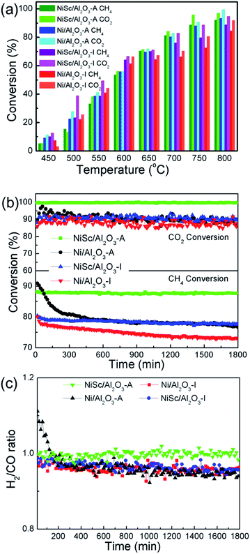
3.2 Catalytic performance
Fig. 6a shows the performance of the Ni/Al2O3-I, NiSc/Al2O3-I, Ni/Al2O3-A, and NiSc/Al2O3-A catalysts for the DRM reaction at the same space velocity. All catalysts exhibited upward trends for the CH4 and CO2 conversions with the rising of reaction temperature. In general, the conversion of CO2 was slightly higher than that of CH4, caused by accompanying reverse water–gas shift reaction.57 For the NiSc/Al2O3-A catalyst, the highest conversion of CH4 of 93.2% was obtained at 800 °C. The conversion of CH4 over the Ni/Al2O3-I and NiSc/Al2O3-I catalysts was higher than that of the other catalysts before 650 °C as the Ni/Al2O3-I and NiSc/Al2O3-I catalysts contained a slightly higher amount of Ni species, as determined by ICP. However, the activities of the NiSc/Al2O3-A and Ni/Al2O3-A catalysts were higher than that of the NiSc/Al2O3-I and Ni/Al2O3-I catalysts at temperatures greater than 650 °C. The excellent structure of the catalysts resulted in better conversion of CH4 over the Ni/Al2O3-A and NiSc/Al2O3-A catalysts. As compared with that of Ni/Al2O3-I, the conversion of CH4 over the NiSc/Al2O3-I catalyst was higher, indicating DRM performance of the catalysts improved by the incorporation of Sc. The NiSc/Al2O3-A catalyst exhibited the best catalytic performance, caused by the incorporation of Sc and structure of the aerogel. Table 4 lists the measured initial and final CH4 turnover frequencies (TOFCH4) of all catalysts. It should be noted that the NiSc/Al2O3-A catalyst show higher TOF value as compared with the other catalysts. The catalytic rate determined from H2 chemisorption was normalized to the exposed Ni sites. Obviously, the Sc addition and generation of Al–O–Ni in the aerogel structure can inhibit the migration of Ni specie and improve the Ni dispersion, and thus, the aerogel catalysts can still maintain the higher Ni dispersion after long-time stability tests (Table S1†). As compared, the Ni dispersion of the Ni/Al2O3-I catalyst is decreased obviously. As a result, the NiSc/Al2O3-A catalyst exhibited outstanding DRM activities. After operation, the Ni dispersion of the Ni/Al2O3-A catalyst was higher than that of Ni/Al2O3-I catalyst, suggesting that the mesoporous structure limits the sintering of Ni species to a certain extent. The loss of activity for the NiSc/Al2O3-I and NiSc/Al2O3-A catalysts was less than that for the Ni/Al2O3-I and Ni/Al2O3-A catalysts, caused by the incorporation of Sc, resulting in the strengthening of the interaction between the γ-Al2O3 support and Ni. For investigating the durability of catalysts, catalytic activity and energy consumption were comprehensively considered, and 750 °C was selected as the optimum reaction temperature.| Catalysts | TOFCH4b (s−1)t1=10 min | TOFCH4b (s−1)t2=360 min | Active loss (%) |
|---|---|---|---|
a Condition: temperature: 550 °C, 50 mg of catalysts, CH4![[thin space (1/6-em)]](https://www.rsc.org/images/entities/char_2009.gif) : :![[thin space (1/6-em)]](https://www.rsc.org/images/entities/char_2009.gif) CO2 = 1 CO2 = 1![[thin space (1/6-em)]](https://www.rsc.org/images/entities/char_2009.gif) : :![[thin space (1/6-em)]](https://www.rsc.org/images/entities/char_2009.gif) 1, 45 mL min−1 per reactor, time: 360 min.b Calculated by the reaction rate of CH4 over the number of exposed Ni atoms per gram of catalyst (moleCH4 h−1 suf. Ni). 1, 45 mL min−1 per reactor, time: 360 min.b Calculated by the reaction rate of CH4 over the number of exposed Ni atoms per gram of catalyst (moleCH4 h−1 suf. Ni). |
|||
| NiSc/Al2O3-A | 5.94 | 5.78 | 2.69 |
| Ni/Al2O3-A | 6.08 | 5.13 | 15.63 |
| NiSc/Al2O3-I | 5.89 | 5.56 | 5.60 |
| Ni/Al2O3-I | 6.31 | 5.49 | 13.00 |
Fig. 6b shows the results obtained from the stability test of various Ni catalysts conducted for 1800 min. At the start, the conversion of CH4 over the Ni/Al2O3-A catalyst was 90.8%. However, after 390 min, the conversion of CH4 significantly decreased (from 90.8% to 80.2%) for the Ni/Al2O3-A catalysts, and then the conversion of CH4 continued to decrease thereafter (from 80.2% to 76.6%). Simultaneously, the conversion of CO2 decreased from 89.7% to 87.3%. At the start, the conversion values of CO2 and CH4 over the Ni/Al2O3-I catalysts were 89.5% and 80.0%, respectively, and then decreased to 87.3% and 72.8%, respectively, at the end of the reaction. The Ni/Al2O3-I and Ni/Al2O3-A catalysts exhibited poor stability, indicative of the agglomeration of Ni nanoparticles and the coke formation. Both of them could lead to the catalysts deactivation under a long-term duration. For the NiSc/Al2O3-I catalysts, simultaneous decrease was observed for the conversion of CH4 from 80.4% to 77.8% within 1800 min and for the conversion of CO2 from 91.7% to 89.3%. Notably, for the NiSc/Al2O3-A catalyst, the conversion of CH4 just decreased by 0.5% (from 88.1 to 87.6%), while the conversion of CO2 barely changed. The NiSc/Al2O3-I catalyst exhibited a long-term stability greater than those of Ni/Al2O3-A and Ni/Al2O3-I catalyst, suggesting that incorporated Sc improves the stability of the catalysts. The Ni/Al2O3-A catalyst exhibited an initial conversion of CH4 higher than those of Ni/Al2O3-I and NiSc/Al2O3-I catalysts, indicating that the aerogel structure increases the catalytic activity, which is in agreement with results obtained from the catalytic activity. The conversion of CH4 remained stable throughout the 1800 min of time on stream for the NiSc/Al2O3-A catalyst. Moreover, all of the catalysts were further tested under lower temperature for 360 min. Inspiringly, the NiSc/Al2O3-A catalyst modified catalysts exhibits better stability as compared to other catalysts, illustrating the advantages of the Sc doping and the unique preparation method. According to the XPS and TPR analysis, the introduction of Sc could effectively enrich the oxygen vacancies and strengthen the interaction between Ni species and Al2O3 support. Additionally, the EDX-mapping results revealed that the addition of Sc species was well dispersed in the aerogel structure, which further enhanced the promotion effect of Sc. Therefore, the sintering of Ni nanoparticle and carbon deposition can be depressed in the NiSc/Al2O3-A catalysts, there after lead to the outstanding catalytic stability.
Fig. 6c shows the H2/CO ratio of various catalysts. The H2/CO ratios of all catalysts, except the NiSc/Al2O3-A catalyst, decreased with time on stream, indicative of the enhancement of the reverse water–gas shift reaction (CO2 + H2 → CO + H2O). The instability of the H2/CO ratios was related to the Boudouard reaction and decomposition of methane at high temperatures, resulting in the increase of CO2 and CH4 conversions.58 The methane decomposition and Boudouard reaction was favored at high temperatures. The NiSc/Al2O3-A catalyst exhibited the highest and the most stable H2/CO ratio. Because the NiSc/Al2O3-A catalyst exhibited a smaller Ni size and larger surface area, the adsorption and activation of reactant gas could be strengthened. Simultaneously, the mesoporous structure could limit the sintering of the Ni species. In addition, the incorporation of Sc was effective for suppressing the deposition of coke, attributed to the enhanced vacancy oxygen, and interaction between the γ-Al2O3 support and Ni nanoparticles.
3.3 Characteristics of the used catalysts
The accumulation of carbon over the spent catalysts is typically quantified by TG and TPO, which is a critical issue for catalyst deactivation.59 Fig. 7a shows the TG results; with increasing temperature, the curves exhibited a downward trend, attributed to the removal of carbon. The weight loss was calculated at 110 °C for excluding the interference by water. The total weight losses of the used Ni/Al2O3-I, NiSc/Al2O3-I, Ni/Al2O3-A, and NiSc/Al2O3-A catalysts were 35.0%, 36.1%, 47.7% and 24.2%, respectively. Compared with that of the Ni/Al2O3-I catalyst, the anti-coke performance of the NiSc/Al2O3-I and Ni/Al2O3-A catalysts was not improved, as indicated by the TG results. The used Ni/Al2O3-A catalyst exhibited the highest weight loss, suggesting that the most amount of carbon is deposited on the catalyst. This result is attributed to the sintering of the Ni0 species, which exhibited weak interaction with the γ-Al2O3 support. The sintering of Ni leads to large Ni nanoparticles, resulting in high carbon deposition. For the Ni/Al2O3-A catalyst, it showed the higher initial CH4 conversion due to the highly dispersed Ni species of aerogel structure compared with Ni/Al2O3-I catalyst. With the reaction going on, the carbon deposited on the exposed active Ni sites which caused the catalyst deactivation. Furthermore, the surrounded mesoporous channels of aerogel can provide the reactants with the routes to the surface of Ni. When the graphitized carbon species deposited on the stable Ni sites, it could lead to catalyst deactivation easily. Therefore, the matrix of aerogel can inhibit the migration of Ni particles to prevent the metal sintering under the DRM reaction, but the carbon deposited on the stable Ni sites could also lead to the deactivation of catalysts. Thus, we used Sc as the promoter to improve the coke resistance of the aerogel catalyst. The used NiSc/Al2O3-A catalyst exhibited a minimum weight loss; this observation indicated that a minimum amount of coke is deposited on the catalyst during DRM. Fig. 7b shows the type of coke species located on the spent samples by the O2-TPO decomposition, resulting in amount of carbon deposition. Depending on the different temperatures, three carbon species denoted as Cα (150–220 °C), Cβ (530–600 °C), and Cγ (>650 °C), respectively, were identified over Ni-based catalyst.33,60 Among them, Cα is mainly formed by the decomposition of CH4 in the initial stage of DRM reaction, which could be easily removed as the reaction time progresses, and Cβ and Cγ represent inert carbon species, which are formatted with the subsequent reaction on stream.13,23,61 CH4 reacted with CO2 to produce CO, which could build graphite carbon Cβ carbon and Cγ by a disproportionate reaction; hence, Cβ and Cγ accompany the whole DRM reaction. Inert carbon (Cβ and Cγ) was one of the main causes for catalyst passivation.52 Interestingly, diverse oxidation abilities of coke species deposited on the spent catalysts can be observed in the TPO profiles of the catalysts. Two peaks were observed at 611 °C, 677 °C and at 636 °C, 743 °C in the curves of the Ni/Al2O3-I and NiSc/Al2O3-I catalysts, respectively. The Ni/Al2O3-A catalyst also exhibited two peaks at 704 °C and 786 °C, respectively. However, the curve of NiSc/Al2O3-A catalyst only exhibited one peak at 704 °C. The peak area of the NiSc/Al2O3-A catalyst was clearly less than those of the other three catalysts, illustrating that the least carbon disposition is deposited on NiSc/Al2O3-A catalyst.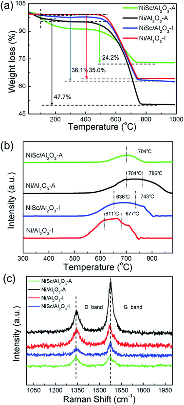 | ||
| Fig. 7 (a) TG profiles; (b) TPO profiles and (c) Raman spectra of various catalysts stability tests for 1800 min. | ||
The Raman spectra analysis was performed for the in-depth study of the carbon species located on the used catalysts. As shown in Fig. 7c, in the Raman spectra of all spend catalysts, two distinct peaks were located at 1580 (G band) and 1340 cm−1 (D band), respectively.62 The D band corresponded to the disorder-induced band, attributed to structural imperfections existing in defective carbon materials. The G band corresponded to graphitic carbon, attributed to the in-plane C–C stretching vibrations of pairs of sp2 atoms in coke.63,64 The intensity of the D band was clearly less than that of the G band over all used catalysts, implying the high yield of significantly higher than that over the other two used catalysts, graphitic carbon species. For the used Ni/Al2O3-A catalyst, the intensities of the G and D bands were significantly higher than those of the other catalysts, and coke disposition was indicating that the aerogel structure does not enhance coking resistance. For the used NiSc/Al2O3-I catalyst, the D band was significantly lower than the G band, indicating that the amount of defective carbon was less than graphitic carbon deposited on NiSc/Al2O3-I. Meanwhile, the intensity of G band for NiSc/Al2O3-I and NiSc/Al2O3-A catalysts significantly lower than that of Ni/Al2O3-I and Ni/Al2O3-A catalysts. This result indicated that the amount of graphitic carbon on NiSc/Al2O3-I and NiSc/Al2O3-A catalysts was less than that of on used Ni/Al2O3-I and Ni/Al2O3-A catalysts. This result was in agreement with those obtained from TPO and TG analysis. Taking the above results into consideration, Sc doping could significantly enhance the anti-coking performance of the aerogel catalysts. Meanwhile, the unique preparation method could generate the well diffusion of Sc additives, increase the oxygen vacancy content in aerogel catalysts and further enhance the coke-resistance of NiSc/Al2O3-A catalysts. Therefore, it is reasonable to deduce the superior catalytic stability of NiSc/Al2O3 catalysts is closely related to those favorable factors.
TEM observations revealed a clear phenomenon for the used catalysts. The formation of coke is well known to be the main features causing catalyst deactivation. As discussed above, three types of coke species can be generated during the DRM reaction: crystalline graphite, filaments and amorphous carbon. Among them, crystalline graphite is responsible for the serve deactivation. As shown in Fig. 9, the used NiSc/Al2O3-A catalyst maintained the mesoporous structure after the duration test. The inset of Fig. 8 shows the corresponding histograms, which exhibit the particle size distribution: the average size of the active Ni nanoparticles was 12–16 nm. The size of Ni nanoparticles was calculated from the (111) peak of the used NiSc/Al2O3-A catalyst from XRD patterns using the Scherrer equation (Fig. S4†). The average size of Ni nanoparticles was 15.37 nm. The size of Ni nanoparticles was believed to not increase significantly, caused by the mesostructure of the support and incorporation of Sc. The type of coke on the surface of the NiSc/Al2O3-A catalyst mainly consisted of filaments; hence, the NiSc/Al2O3-A catalyst still maintains good catalytic stability. For the Ni/Al2O3-A catalyst (Fig. S5†), crystalline graphite blocked the stable mesoporous channels, resulting in catalytic deactivation. Through the above analysis, the addition of Sc clearly resulted in a change in the type of coke (Fig. S6†), which actually contributed to the outstanding catalytic stability. For the Ni/Al2O3-A catalyst, the layered carbon was easily formatted, and the carbon species completely covered the Ni nanoparticle surface, thereby cutting off the contact between reactant gas and Ni nanoparticles and resulting in a sharp decrease in the conversion of CH4 (Fig. S6a†). For the NiSc/Al2O3-A catalyst, carbon nanotubes were the main carbon species, and they did not completely cover the Ni nanoparticles, caused by the incorporation Sc, thereby rendering good catalytic stability (Fig. S6b†). Similarly, the incorporated Sc could improve the stability of the NiSc/Al2O3-A catalyst as compared with that of the Ni/Al2O3-A catalyst. The Sc additives not only enhanced the content of vacancy oxygen in catalysts, but also changed the type of the carbon deposition. Therefore, the NiSc/Al2O3-A catalyst exhibited excellent catalytic stability.
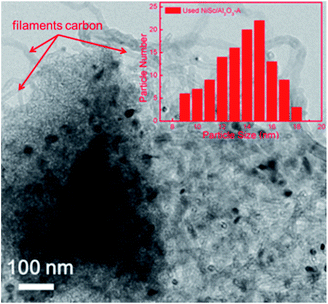 | ||
| Fig. 8 TEM image and nickel particle size distributions of NiSc/Al2O3-A catalyst after 1800 min tested. | ||
3.4 Possible catalytic mechanism
According to previous studies, a possible mechanism has been proposed for DRM over the NiSc/Al2O3-A catalyst.65 As shown in Fig. 9, CH4 and CO2 adsorbed on the active Ni nanoparticles decompose to active intermediates CHx and O*, respectively,66 which can react with each other and produce CO and H2. On the other hand, the lattice oxygen, produced from the dissociation of CO2, and the mobile oxygen could be transferred to the nearby Ni nanoparticles and react with CHx.67 The oxygen vacancies and oxygen mobility played a significant role in the catalytic performance during DRM. Form the XPS results, the incorporation of Sc could contribute to the increase of oxygen vacancies on catalyst surface. Moreover, the Sc additives were well dispersed in the aerogel catalysts and raised the strong interaction between active components and Al2O3 support, which further enhanced the vacancy oxygen contents of NiSc/Al2O3-A catalyst. The oxygen vacancies are confirmed to promote the activation and reduction of CO2, which eliminated the carbon deposited on the Ni nanoparticle surface by the decomposition of methane.68,69 Additionally, Ni nanoparticles could be formed and anchored in the porous framework during the reduction process, limited the sintering of Ni species. Thus, the NiSc/Al2O3-A catalyst exhibited excellent performance in the DRM reaction.4. Conclusions
In summary, Sc promoted and aerogel confined Ni catalysts was prepared by a sol–gel method, followed by the sublimation of organic solvent. Benefiting from effective doping of Sc, the NiSc/Al2O3-A catalysts exhibited high active surface oxygen and basic site contents, while the type of coke species formatted on the catalysts were also changed. Meanwhile, the unique preparation method could lead to that Sc additives were well dispersed in the aerogel catalysts. In addition, more oxygen vacancies could be generated in NiSc/Al2O3-A catalyst, which led to the better anti-coking performance. So, NiSc/Al2O3-A catalyst exhibited excellent catalytic stability. Additionally, as compared to the Ni/Al2O3-I and NiSc/AlO3-I catalyst, the Ni/Al2O3-A catalyst exhibited more highly dispersed Ni species, indicating that the sol–gel method successfully immobilizes the Ni species into the porous framework of the Al2O3 aerogel, which limiting the sintering of Ni nanoparticles. Because the Sc additives were well dispersed in the aerogel catalysts by unique preparation method, the NiSc/Al2O3-A catalyst exhibited excellent catalytic stability, activity, and good coking-resistance. Hence, the NiSc/Al2O3-A catalyst demonstrates promise as a catalyst for the DRM reaction.Acknowledgements
The authors acknowledge the support of the National Natural Science Foundation of China (U1462110). The authors would like to thank T. Xie, S. Cai and H. Wang for their help contributions towards the experimental setup and measurement of various parameters.References
- L. V. Mattos, G. Jacobs, B. H. Davis and F. B. Noronha, Chem. Rev., 2012, 112, 4094–4123 CrossRef CAS PubMed.
- C. Liu, J. Ye, J. Jiang and Y. Pan, ChemCatChem, 2011, 3, 529–541 CrossRef CAS.
- D. Pakhare and J. Spivey, Chem. Soc. Rev., 2014, 43, 7813–7837 RSC.
- S. Li and J. Gong, Chem. Soc. Rev., 2014, 43, 7245–7256 RSC.
- T. V. Choudhary and V. R. Choudhary, Angew. Chem., Int. Ed., 2008, 47, 1828–1847 CrossRef CAS PubMed.
- T. H. Nguyen, A. Łamacz, A. Krztoń, A. Ura, K. Chałupka, M. Nowosielska, J. Rynkowski and G. Djéga-Mariadassou, Appl. Catal., B, 2015, 165, 389–398 CrossRef CAS.
- G. A. Olah, A. Goeppert, M. Czaun and G. K. S. Prakash, J. Am. Chem. Soc., 2013, 135, 648–650 CrossRef CAS PubMed.
- C. Chen, Y.-H. Yeh, M. Cargnello, C. B. Murray, P. Fornasiero and R. J. Gorte, ACS Catal., 2014, 4, 3902–3909 CrossRef CAS.
- M. Yang and H. Papp, Catal. Today, 2006, 115, 199–204 CrossRef CAS.
- A. Peters, F. Nouroozi, D. Richter, M. Lutecki and R. Gläser, ChemCatChem, 2011, 3, 598–606 CrossRef CAS.
- L. Xu, H. Song and L. Chou, ACS Catal., 2012, 2, 1331–1342 CrossRef CAS.
- T. Xie, L. Shi, J. Zhang and D. S. Zhang, Chem. Commun., 2014, 50, 7250–7253 RSC.
- X. Du, D. S. Zhang, L. Shi, R. Gao and J. Zhang, Nanoscale, 2013, 5, 2659–2663 RSC.
- M.-S. Fan, A. Z. Abdullah and S. Bhatia, ChemSusChem, 2011, 4, 1643–1653 CrossRef CAS PubMed.
- J. Wei and E. Iglesia, J. Catal., 2004, 224, 370–383 CrossRef CAS.
- C. Dai, S. Zhang, A. Zhang, C. Song, C. Shi and X. Guo, J. Mater. Chem. A, 2015, 3, 16461–16468 CAS.
- S. Y. Foo, C. K. Cheng, T.-H. Nguyen, E. M. Kennedy, B. Z. Dlugogorski and A. A. Adesina, Catal. Commun., 2012, 26, 183–188 CrossRef CAS.
- M. García-Diéguez, I. S. Pieta, M. C. Herrera, M. A. Larrubia and L. J. Alemany, J. Catal., 2010, 270, 136–145 CrossRef.
- J. Ashok and S. Kawi, ACS Catal., 2014, 4, 289–301 CrossRef CAS.
- J. Ashok and S. Kawi, Int. J. Hydrogen Energy, 2013, 38, 13938–13949 CrossRef CAS.
- Z. Liu, J. Zhou, K. Cao, W. Yang, H. Gao, Y. Wang and H. Li, Appl. Catal., B, 2012, 125, 324–330 CrossRef CAS.
- J. Lu, B. Fu, M. C. Kung, G. Xiao, J. W. Elam, H. H. Kung and P. C. Stair, Science, 2012, 335, 1205–1208 CrossRef CAS PubMed.
- T. Xie, X. Zhao, J. Zhang, L. Shi and D. S. Zhang, Int. J. Hydrogen Energy, 2015, 40, 9685–9695 CrossRef CAS.
- X. Du, D. S. Zhang, R. Gao, L. Huang, L. Shi and J. Zhang, Chem. Commun., 2013, 49, 6770–6772 RSC.
- N. Wang, K. Shen, X. Yu, W. Qian and W. Chu, Catal. Sci. Technol., 2013, 3, 2278–2287 CAS.
- X. Zhang, N. Wang, Y. Xu, Y. Yin and S. Shang, Catal. Commun., 2014, 45, 11–15 CrossRef CAS.
- H. Tian, X. Li, L. Zeng and J. Gong, ACS Catal., 2015, 5, 4959–4977 CrossRef CAS.
- X. Zheng, S. Tan, L. Dong, S. Li and H. Chen, Chem. Eng. J., 2015, 265, 147–156 CrossRef CAS.
- Z. Li, Y. Kathiraser and S. Kawi, ChemCatChem, 2015, 7, 160–168 CrossRef CAS.
- Z. Li, Y. Kathiraser, J. Ashok, U. Oemar and S. Kawi, Langmuir, 2014, 30, 14694–14705 CrossRef CAS PubMed.
- S. Wei, Q. Wang, J. Zhu, L. Sun, H. Lin and Z. Guo, Nanoscale, 2011, 3, 4474–4502 RSC.
- J. C. Park, J. U. Bang, J. Lee, C. H. Ko and H. Song, J. Mater. Chem., 2010, 20, 1239–1246 RSC.
- D. Liu, X. Y. Quek, W. N. E. Cheo, R. Lau, A. Borgna and Y. Yang, J. Catal., 2009, 266, 380–390 CrossRef CAS.
- T. Huang, W. Huang, J. Huang and P. Ji, Fuel Process. Technol., 2011, 92, 1868–1875 CrossRef CAS.
- S. Zhang, S. Muratsugu, N. Ishiguro and M. Tada, ACS Catal., 2013, 3, 1855–1864 CrossRef CAS.
- Z. Hao, Q. Zhu, Z. Jiang, B. Hou and H. Li, Fuel Process. Technol., 2009, 90, 113–121 CrossRef CAS.
- L. Chen, Q. Zhu and R. Wu, Int. J. Hydrogen Energy, 2011, 36, 2128–2136 CrossRef CAS.
- J. Zhu, X. Peng, L. Yao, D. Tong and C. Hu, Catal. Sci. Technol., 2012, 2, 529–537 CAS.
- N. Wang, K. Shen, L. Huang, X. Yu, W. Qian and W. Chu, ACS Catal., 2013, 3, 1638–1651 CrossRef CAS.
- N. Wang, W. Chu, T. Zhang and X. S. Zhao, Int. J. Hydrogen Energy, 2012, 37, 19–30 CrossRef CAS.
- M. Selvaraj, D.-W. Park and C. S. Ha, Microporous Mesoporous Mater., 2011, 138, 94–101 CrossRef CAS.
- N. Laosiripojana, W. Sutthisripok and S. Assabumrungrat, Chem. Eng. J., 2005, 112, 13–22 CrossRef CAS.
- A. S. Al-Fatesh, M. A. Naeem, A. H. Fakeeha and A. E. Abasaeed, Bull. Korean Chem. Soc., 2015, 36, 2081–2088 CrossRef CAS.
- L. Ren, S. Cui, F. Cao and Q. Guo, Angew. Chem., Int. Ed., 2014, 53, 10147–10149 CrossRef CAS PubMed.
- T. Osaki, T. Horiuchi, T. Sugiyama, K. Suzuki and T. Mori, Catal. Lett., 1998, 52, 171–180 CrossRef CAS.
- J. G. Seo, M. H. Youn, J. C. Jung and I. K. Song, Int. J. Hydrogen Energy, 2010, 35, 6738–6746 CrossRef CAS.
- J. G. Seo, M. H. Youn, Y. Bang and I. K. Song, Int. J. Hydrogen Energy, 2010, 35, 12174–12181 CrossRef CAS.
- J. G. Seo, M. H. Youn and I. K. Song, Catal. Surv. Asia, 2010, 14, 1–10 CrossRef CAS.
- Y. Kathiraser, W. Thitsartarn, K. Sutthiumporn and S. J. Kawi, J. Phys. Chem. C, 2013, 117, 8120–8130 CAS.
- Q. Wei, G. Yang, Y. Yoneyama, T. Vitidsant and N. Tsubaki, Catal. Today, 2016, 265, 36–44 CrossRef CAS.
- A. Garcia-Gallastegui, D. Iruretagoyena, M. Mokhtar, A. M. Asiri, S. N. Basahel, S. A. Al-Thabaiti, A. O. Alyoubi, D. Chadwick and M. S. P. Shaffer, J. Ind. Eng. Chem., 2014, 20, 549–557 CrossRef.
- A. E. C. Palmqvist, M. Wirde and U. Gelius, Nanostruct. Mater., 1999, 11, 995–1007 CrossRef CAS.
- L. Gan, L. Ye, M. Liu, S. Tao and K. Xie, RSC Adv., 2016, 6, 641–647 RSC.
- M. Cargnello, M. Grzelczak, B. Rodrıguez-González, Z. Syrgiannis, K. Bakhmutsky, V. L. Parola, L. M. Liz-Marzán, R. J. Gorte, M. Prato and P. Fornasiero, J. Am. Chem. Soc., 2012, 134, 11760–11766 CrossRef CAS PubMed.
- S. A. S. Gomez and F. M. J. Geiger, J. Phys. Chem. A, 2014, 118, 10974–10981 CrossRef PubMed.
- L. Zhang, D. S. Zhang, J. Zhang, S. Cai, C. Fang, L. Huang, H. Li, R. Gao and L. Shi, Nanoscale, 2013, 5, 9821–9829 RSC.
- J. Gao, H. Lou and X. Zheng, Fuel Cells, 2011, 191–221 Search PubMed.
- M. C. J. Bradford and M. A. Vannice, Appl. Catal., A, 1996, 142, 97–122 CrossRef CAS.
- X. Yu, N. Wang, W. Chu and M. Liu, Chem. Eng. J., 2012, 209, 623–632 CrossRef CAS.
- W. D. Zhang, B. S. Liu, C. Zhu and Y. L. Tian, Appl. Catal., A, 2005, 292, 138–143 CrossRef CAS.
- J. Guo, H. Lou and X. Zheng, Carbon, 2007, 45, 1314–1321 CrossRef CAS.
- X. Du, D. S. Zhang, L. Shi, R. Gao and J. Zhang, J. Phys. Chem. C, 2012, 116, 10009–10016 CAS.
- A. R. McFarlane, I. P. Silverwood, E. L. Norris, R. M. Ormerod, C. D. Frost, S. F. Parker and D. Lennon, Chem. Phys., 2013, 427, 54–60 CrossRef CAS.
- D. Liu, Y. Wang, D. Shi, X. Jia, X. Wang, A. Borgna, R. Lau and Y. Yang, Int. J. Hydrogen Energy, 2012, 37, 10135–10144 CrossRef CAS.
- X.-Y. Quek, D. Liu, W. N. E. Cheo, H. Wang, Y. Chen and Y. Yang, Appl. Catal., B, 2010, 95, 374–382 CrossRef CAS.
- S. Kado, K. Imagawa, A. Kiryu, F. Yagi, T. Minami, H. Kawai, K. Kawazuishi, K. Tomishige, A. Nakamura and Y. Suehiro, Catal. Today, 2011, 171, 97–103 CrossRef CAS.
- S. M. Lima, A. M. Silva, L. O. O. Costa, U. M. Graham, G. Jacobs, B. H. Davis, L. V. Mattos and F. B. Noronha, J. Catal., 2009, 268, 268–281 CrossRef.
- L. Pino, A. Vita, F. Cipitì, M. Laganà and V. Recupero, Appl. Catal., B, 2011, 104, 64–73 CrossRef CAS.
- D. K. Kim, K. Stöwe, F. Müller and W. F. Maier, J. Catal., 2007, 247, 101–111 CrossRef CAS.
Footnote |
| † Electronic supplementary information (ESI) available: Preparation of Ni/Al2O3-I and NiSc/Al2O3-I catalysts in details, TEM images of various catalysts and TEM images of NiSc/Al2O3-A catalysts after 1800 min stability tests. See DOI: 10.1039/c6ra27266e |
| This journal is © The Royal Society of Chemistry 2017 |

