 Open Access Article
Creative Commons Attribution 3.0 Unported Licence
In situ controllable synthesis of cotton-like polyaniline nanostructures for a H2O2 sensor using an embedded three-electrode microfluidic chip†
Mojie Suna,
Guoqing Songab,
Jingjing Liu *b,
Hongmei Chenb and
Fuqiang Nie*b
aDepartment of Chemical Engineering, Northeast Electric Power University, Jilin, China. E-mail: smoj@sina.com
bDivision of Nanobionic Research, Suzhou Institute of Nano-Tech and Nano-Bionics, Chinese Academy of Sciences, Suzhou, China. E-mail: fqnie2012@sinano.ac.cn; jjliu2015@sinano.ac.cn
First published on 28th February 2017
Abstract
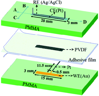
A robust embedded three-electrode microfluidic chip (TEMC) was designed for the in situ electrochemical synthesis of polyaniline (PANI) nanostructures. PANI doped with poly-vinylsulphonic acid (PVS) was electrochemically produced at a channel coated with a thin gold layer as the working electrode material. The resultant material formed a conductive monolithic PANI/PVS film with cotton-like nanostructures. The thickness and porosity of the polymeric material can be controlled by the polymerization conditions, i.e., the number of potential cycles. Horseradish peroxidase (HRP) was subsequently electrostatically immobilized on the monolithic PANI/PVS film. This modified PANI/PVS/HRP material, obtained using a TEMC, showed a good linear response over a range of 0.01–0.6 mM and 1–60 mM for hydrogen peroxide detection and exhibited good reproducibility. This TEMC design could provide a simple and reliable approach for enzyme-based biosensor fabrication.
1. Introduction
As an important industrial material, H2O2 has been widely used in the food industry and is inevitably present in wastewater. Moreover, H2O2 is a product of enzymatic reactions in coupled enzyme systems. Unfortunately, H2O2 is extremely toxic to cellular life,1 so the detection of H2O2 is of practical importance in pharmaceutical, clinical, industrial, environmental, and many other fields.2 H2O2 has been detected by volumetric, colorimetric and chemiluminescence spectrometry,3,4 but these techniques suffer from various interferences, long analysis times and usage of expensive reagents.Since the concept of a micro-total analysis system (μ-TAS) was proposed by Manz et al. in 1990, significant advancements have been made towards the development of highly miniaturized analytical systems.5 The advantages of a microfluidic platform are process integration, portability, small sample volumes, and high throughput analysis.2 Particularly, electrochemical detection, e.g., amperometry, has been perfectly incorporated into miniaturized analytical systems not only due to the inherent miniaturization and portability, but also due to the extremely low costs, low power requirements and compatibility with microfabrication technology.6
Amperometric biosensors made of organic conducting polymers, such as polyanilines (PANI), polyindoles, polycarbazoles, polypyrroles and polythiophenes, have attracted tremendous interest for their simple operation, high operational stability, fast response, and very low limit of detection.7 Among the polymers, PANI has been studied extensively owing to its easy preparation, low cost, performance, stability, and unique electrical, electrochemical and optical properties.8,9 Furthermore, PANI is compatible with biological molecules in neutral aqueous solutions, so it is utilized as an excellent platform to immobilize biomolecules.10 PANI can also act as a rapid electron mediator due to its excellent conductivity and electroactivity.11,12 Therefore, PANI is employed in the most promising electrochemical biosensor applications.13 In general, amperometric biosensors are composed of a base electrode substrate coated with a mediator, such as a conducting polymer film and an immobilized biomolecule, e.g., HRP.14 The polymer, PANI, can be electrochemically synthesized through galvanostatic, potentiostatic or potentiodynamic methods, which provide the potential to incorporate a wide range of dopants into the formation of the PANI film and provide good control of the thickness to improve the detection performance. However, there are many efforts focused on the study of PANI thin film fabrication on an electrode surface reported in the literature.13,15 Among the applications of PANI films, thickness control has become more important in biosensors. For example, the electron transport efficiency is higher at thinner PANI thicknesses, which can enhance the lower limit of detection. On the other hand, more enzyme can be immobilized at thicker PANI thicknesses to provide a higher limit of detection. Therefore, it is necessary to control the PANI thickness for its real applications. In this study, an embedded three-electrode microfluidic chip (TEMC) is proposed and demonstrated, which integrates three electrodes on a chip-scale for in situ electrochemical polymerization. By adjusting the polymerization conditions, a controllable monolithic PANI film can be fabricated and polymerized, and exhibits cotton-like nanostructures. The feasibility of using a TEMC for an HRP-H2O2 sensing device is demonstrated by amperometric detection. The experimental results indicate that it has a good reproducibility and long-term stability. This robust TEMC with cotton-like PANI nanostructures can be utilised in widespread applications, such as in chip-based biosensors, electrochromatography16 and capacitors.17
2. Experimental section
2.1 Materials and methods
Phosphate buffered saline (PBS, pH = 6.8) was prepared using 0.1 M phosphate buffer, 0.137 M NaCl, and 2.7 mM KCl. The deionized water (resistance > 18 MΩ cm−1) was treated by a Milli-Q system (model: Simplicity direct Q3 UV, Merck Millipore Ltd., Germany).
The morphology and composition of the synthesized PANI were characterized using a scanning electron microscope (SEM) (Quanta 250 FEG, FEI Co. Ltd., USA). Electrochemical measurements were performed using a workstation (model: CHI 660e, CH Instruments, Inc. USA) at room temperature.
3. Results and discussion
3.1 Characterization of the PANI modified electrode
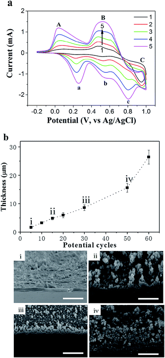
The mixture of aniline, PVS and HCl was utilized to investigate in situ electropolymerization within the TEMC platform. The PANI thin-film can be electrochemically deposited on electrode surfaces using galvanostatic, potentiostatic or potentiodynamic methods. Among them, the formation of a furrowed PANI thin-film was more homogeneous and adhered on the electrode surface using the potential-scanning method.19 PANI thin-films produced in non-acidic media generally did not keep their conductive characterization, which is a severe problem for the development of a PANI/enzyme-based biosensor. Therefore, the electropolymerization process had to be carried out in the presence of a dopant like PVS.20–22 The role of PVS was to maintain the electrical neutrality in the oxidized form of the polymer. Also, PVS can increase the structural stability and conductivity of the polymer over a broader range of pH values.23A mixture of aniline/PVS/HCl was used for all electropolymerization on a gold surface as the WE material by CV at 100 mV s−1 as shown in Fig. 2(a). The CV was typical for PANI/PVS, with three oxidation peaks (A, B and C) and three corresponding reduction peaks (a, b and c) that are comparable to those reported in the literature.24 The polymerization current responses increased with the number of potential cycles, which confirmed that the polymer was conducting and electroactive and indicated that polyaniline had aggregated on the gold surface. It was also found that shifts in peak potentials started to occur after a number of potential cycles, which increased the electrode resistance due to the formation of a thicker PANI/PVS film.25
Currently, most of the research on PANI electro-polymerization has focused on the polymer thin-film on the electrode surface. Herein, we have proposed and demonstrated a different approach to fabricate in situ polymerized monolithic PANI/PVS nanostructures with controllable thickness. It is well known that the polymer thickness was increased by successive potential cycles. To investigate the effects of the number of potential cycles on the polymer thickness, the initial depth of the channel with a gold thin-film as the polymerization site was designed to be 40 μm, which provided enough space for polymer growth from bottom to top in the TEMC. Fig. 2(b) shows the relationship between the number of potential cycles and the thickness of the electro-polymerized PANI/PVS film. Over the range of 5 to 60 potential cycles, the polymer thickness increased from 1.7 to 26.4 μm gradually. Furthermore, the morphology of the PANI/PVS film became more porous, which was caused by the rough contact surface during polymerization by increasing the number of potential cycles as shown in the SEM images in Fig. 2(b). The experimental results indicated that the thickness of the PANI/PVS film was definitely controllable. Furthermore, high quality SEM graphs can be seen in the ESI.†
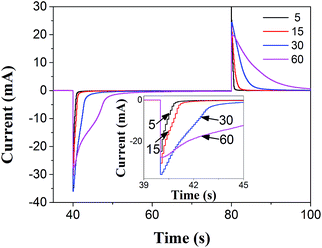
In order to practically evaluate the PANI film developed here, the PANI/PVS film that was used to immobilize HRP in order to realize H2O2 detection was designed as follows. Multi-potential step chronoamperometric measurements were employed to study the effects of the number of potential cycles on the redox switching of the PANI/PVS thin-film to determine the applied number of potential cycles in the fabrication of the biosensor. Fig. 3 shows the chronoamperometric transients upon oxidation (1.0 V) and reduction (0.0 V) of the polymer. It is clear from the results of Fig. 2(b) that more potential cycles resulted in a thicker polymer film, and the results of Fig. 3 show that thicker films exhibit a slower redox switching phenomenon. Grennan et al. studied the influence of the thickness of the PANI film on a variety of amperometric sensor characteristics and found that increasing the polymer thickness resulted in increasing response times of the sensors as well as background and charging currents; the optimal thickness of the thin-film was found to be 13.7 μm.26 There is a tradeoff between polymer thickness and electron transfer properties owing to the fact that a thicker polymer film will hinder the electron transfer properties between the electrode surface and the bulk solution. A thinner polymer film would be preferable for sensor applications.27 Morrin et al. found that the current response decreased in their nanoscale PANI/DBSA biosensor above 30 cycles.28 Therefore, for the following HRP-based biosensor application, the depth of the channel as the electropolymerization site was designed as ∼10 μm, with 30 potential cycles as shown in Fig. 2(b), which ensured the formation of the monolithic polymer.
3.2 Characteristics of TEMC-based H2O2 biosensor
According to the basic amperometric procedure mentioned above, 1 mg mL−1 HRP was electrostatically immobilized onto the monolithic polymer to realize the function of H2O2 sensing. Fig. 4 presents a schematic diagram of the electron transfer mechanism in the enzymatic reaction of the PANI/HRP based H2O2 biosensor. The whole reaction was performed while the PANI was oxidized by H2O2 with the electro-catalysis of HRP. Heme, acting as an active agent in the HRP enzyme, contains Fe3+ and a neutral porphyrin ring (P0). HRP is activated at 30 °C over the environmental pH range of 6–8. In general, the HRP immobilized electrode electrocatalytic reduction of H2O2 can be expressed as follows.| HRP(Fe3+,P0) + H2O2 → compound I (Fe4+,P˙) + H2O | (1) |
| Compound I (Fe4+,P˙) + AH2 → compound II (Fe4+,P0) + AH˙ | (2) |
| Compound II (Fe4+,P0) + AH2 → HRP(Fe3+,P0) + AH˙ | (3) |
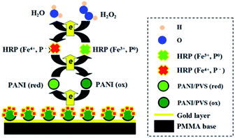 | ||
| Fig. 4 Schematic diagram of the electron transfer mechanism in the enzymatic reaction of the PANI/HRP based H2O2 biosensor. | ||
HRP contains Fe3+ and a neutral porphyrin ring (P0). In the first stage of the cycle reaction, Fe3+ and P0 in the prosthetic group of HRP provide two electrons and form the intermediate compound I. In the second stage, the electron transfer is from AH2 to compound I, which forms compound II and the radical reaction product of AH˙. Finally, compound I and compound II are reduced with the adsorption of a proton. For this electro-catalyzed reaction, the potential of the reduction current of H2O2 is the same as the oxidation potential of compound II. As molecular oxygen is competitive in the ferrous oxide enzyme dioxygen reaction, it is necessary to avoid the impact of dissolved oxygen in the ampere test.
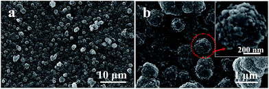
The surface of the film is the outermost part that connects with the external environment in the catalyst reaction, and the nanostructure enables different electronic and catalyst properties to those of bulk materials.29 Fig. 5(a) shows the surface morphology of the PANI/PVS/HRP film synthesized at the channel by 30 potential cycles. The polymer layer exhibited a monolithic structure composed of continuous cotton-like nanostructures with mesopores on the surface as shown in Fig. 5(b). The porous surface enables the film to exhibit good adsorption and have a wide reaction area, both of which have a positive influence on detection.
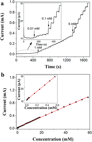
In order to further investigate the characterization of the TEMC-based H2O2 biosensor for the detection of different H2O2 concentrations, we measured the amperometric response to H2O2 using a self designed continuous flow detection system, which can be seen in Fig. S2 (ESI†). Fig. 6(a) shows the calibration curve of the TEMC-based H2O2 biosensor and indicates a linear range of the PANI/PVS/HRP electrode response from 0.01–0.6 mM [Y (mA) = 0.010 + 0.033X (mM), R2 = 0.99973] and 1–60 mM [Y (mA) = 0.032 + 0.016X (mM), R2 = 0.99931] as shown in Fig. 6(b). The detection limit was estimated as 1.49 μM (S/N = 3). At low H2O2 concentrations, the substrate i.e., H2O2 is depleted rapidly as it is converted into product by the catalytic action of PANI/PVS/HRP at the electrode surface, thus resulting in a high sensitivity response. When the H2O2 concentrations increase, the nano-pores supply substrate over a larger time window during the proceeding reaction, and the possibility of reaction products obstructing the electrode surface increases, which results in a lower sensitivity.30
The performance of the TEMC-based H2O2 biosensor compared to those of previous H2O2 sensors based on various PANI/HRP composites is summarized in Table 1. The linear range of the TEMC-based H2O2 biosensor in the upper limit of detection was not comparable to the best result summarized in Table 1. However, the TEMC-based H2O2 biosensor represents two linear ranges, with amperage responses over a wider order of magnitude range from 10−2 to 102 mM, which makes it suitable for use in extensive applications. Furthermore, the performances of the reported sensors are difficult to compare directly due to the use of additional mediators and different working potentials.
| Electrode materials | Detection limit/μM | Liner range/mM | Ref. |
|---|---|---|---|
| PANI/single-wall carbon nanotubes | 0.9 | 2.5–50.0 | 31 |
| Ag nanoparticle/PANI/graphene composites | 30 | 0.25–2.25 | 32 |
| PANI nanotubes | 1.5 | 1–200 | 33 |
| Perchlorate/PANI film | — | 3–136 | 34 |
| Gold doped polyaniline composite | 1.6 | 0.03–2 | 35 |
| Pt nanoparticles doped PANI nanofiber membrane | 2.8 | 7–14 | 36 |
| Cotton-like PANI/PVS nanostructure film | 1.5 | 0.01–0.6 and 1–60 | This work |
Fig. 7 shows the current response to electroactive compounds of 20 mM ascorbic acid (AA) and urea (U) using the TEMC-based H2O2 biosensor at a potential of −0.2 V during the measurement of 2 mM H2O2. The amperometric response to H2O2 is not influenced significantly. Such behavior indicated that the activity towards H2O2 cannot be impacted significantly by the interferences. This can be attributed to the specificity of horseradish peroxidase.
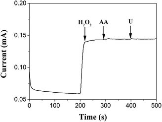 | ||
| Fig. 7 Amperometric response of the PANI/PVS/HRP electrode to 2 mM H2O2, 20 mM ascorbic acid (AA) and 20 mM urea (U), respectively, at a potential of −0.2 V. | ||
The reproducibility was estimated by successive determinations of 2 mM H2O2 with the same TEMC-based H2O2 biosensor; the peak patterns of the amperometric response were kept similar for five consecutive injections and the relative standard deviation (RSD) was better than 5%, which indicated that the system had a good reproducibility and was quite credible. After 50 successive assays, the response remained at 88% of the initial response. This may be a result of the in situ electrochemical polymerization, because the configuration of the channel increased the stability of the polymer and the nano-structure was propitious towards the attachment of HRP.
4. Conclusions
In conclusion, an in situ electrochemical polymerization of a PANI/PVS film with cotton-like nanostructures using TEMC was proposed and demonstrated. The thickness of the PANI/PVS film could be controlled by adjustment of the number of potential cycles, and the film also exhibited good conduction and electroactivity. The polymer film was made porous by increasing the number of potential cycles. The relevant functions were realized by immobilizing HRP on the PANI/PVS film surface. This modified PANI/PVS/HRP material exhibits two linear responses over the ranges of 0.01–0.6 mM and 1–60 mM for hydrogen peroxide detection. The broad linear detection range, low detection limit, high sensitivity and acceptable reproducibility of the material would make it capable of acting as a good alternative for H2O2 sensors.Acknowledgements
This research work was supported by the National Natural Science Foundation of China (grant number 21271182), the Major National Science Research Program (973 Program, grant number 2013CB933000), and the Jiangsu Natural Science Youth Foundation (grant number BK20160398).References
- Q. Shi, Y. Song, C. Zhu, H. Yang, D. Du and Y. Lin, ACS Appl. Mater. Interfaces, 2015, 7, 24288–24295 CAS.
- T. Ruzgas, E. Csoregi, J. Emneus, L. Gorton and G. MarkoVarga, Anal. Chim. Acta, 1996, 330, 123–138 CrossRef CAS.
- S. G. Rhee, T. S. Chang, W. Jeong and D. Kang, Mol. Cells, 2010, 29, 539–549 CrossRef CAS PubMed.
- A. Roda, M. Mirasoli, E. Michelini, M. Di Fusco, M. Zangheri, L. Cevenini, B. Roda and P. Simoni, Biosens. Bioelectron., 2016, 76, 164–179 CrossRef CAS PubMed.
- A. Manz, N. Graber and H. M. Widmer, Sens. Actuators, B, 1990, 1, 244–248 CrossRef CAS.
- V. N. Goral, N. V. Zaytseva and A. J. Baeumner, Lab Chip, 2006, 6, 414–421 RSC.
- K. Lee, S. Cho, S. H. Park, A. J. Heeger, C. W. Lee and S. H. Lee, Nature, 2006, 441, 65–68 CrossRef CAS PubMed.
- C. Sheng and S. Gang, ACS Appl. Mater. Interfaces, 2013, 5, 6473–6477 Search PubMed.
- L. Tiggemann, S. Ballen, C. Bocalon, A. M. Graboski, A. Manzoli, P. S. D. P. Herrmann, J. Steffens, E. Valduga and C. Steffens, J. Food Eng., 2016, 180, 16–21 CrossRef CAS.
- J. Liu, S. Lu, X. Liang, Q. Gan, Y. Wang and H. Li, J. Electroanal. Chem., 2016, 764, 15–22 CrossRef CAS.
- B. Yu, J. Song, Y. Mao, D. Han, F. Yang, N. Li and A. Ivaska, Electroanalysis, 2011, 23, 878–884 CrossRef.
- L. Chen, Z. Su, X. He, Y. Liu, C. Qin and Y. Zhou, Electrochem. Commun., 2012, 15, 34–37 CrossRef CAS.
- C. Dhand, M. Das, M. Datta and B. D. Malhotra, Biosens. Bioelectron., 2011, 26, 2811–2821 CrossRef CAS PubMed.
- S. Bao, M. Du, M. Zhang, H. Zhu, P. Wang, T. Yang and M. Zou, Chem. Eng. J., 2014, 258, 281–289 CrossRef CAS.
- A. T. Lawal and G. G. Wallace, Talanta, 2014, 119, 133–143 CrossRef CAS PubMed.
- J. Zhang, W. Zhang, T. Bao and Z. Chen, J. Chromatogr. A, 2014, 1339, 192–199 CrossRef CAS PubMed.
- Y. E. Miao, W. Fan, D. Chen and T. Liu, ACS Appl. Mater. Interfaces, 2013, 5, 4423–4428 CAS.
- K. Grennan, A. J. Killard and M. R. Smyth, Electroanalysis, 2005, 17, 1360–1369 CrossRef CAS.
- Q. Xu, J. J. Zhu and X. Y. Hu, Anal. Chim. Acta, 2007, 597, 151–156 CrossRef CAS PubMed.
- N. Prabhakar, G. Sumana, K. Arora, H. Singh and B. D. Malhotra, Electrochim. Acta, 2008, 53, 4344–4350 CrossRef CAS.
- N. C. S. Vieira, E. G. R. Fernandes, A. D. Faceto, V. Zucolotto and F. E. G. Guimarães, Sens. Actuators, B, 2011, 160, 312–317 CrossRef CAS.
- F. Arslan, S. Ustabaş and H. Arslan, Sensors, 2011, 11, 8152–8163 CrossRef CAS PubMed.
- G. Li, Y. Wang and H. Xu, Sensors, 2007, 7, 239–250 CrossRef CAS.
- L. Shahhosseini, M. R. Nateghi, M. Kazemipour and M. B. Zarandi, Prog. Org. Coat., 2015, 88, 272–282 CrossRef CAS.
- M. C. Santos, M. L. Munford and R. F. Bianchi, Mater. Sci. Eng., B, 2012, 177, 359–366 CrossRef CAS.
- K. Grennan, A. J. Killard, C. J. Hanson, A. A. Cafolla and M. R. Smyth, Talanta, 2006, 68, 1591–1600 CrossRef CAS PubMed.
- S. K. Bhardwaj, N. Bhardwaj, G. C. Mohanta, P. Kumar, A. L. Sharma, K. H. Kim and A. Deep, ACS Appl. Mater. Interfaces, 2015, 7, 26124–26130 CAS.
- A. Morrin, O. Ngamna, A. J. Killard, S. E. Moulton, M. R. Smyth and G. G. Wallace, Electroanalysis, 2005, 17, 423–430 CrossRef CAS.
- A. N. Shipway, E. Katz and I. Willner, ChemPhysChem, 2000, 1, 18–52 CrossRef CAS PubMed.
- X.-x. Dong, M.-y. Li, N.-n. Feng, Y.-m. Sun, C. Yang and Z.-l. Xu, RSC Adv., 2015, 5, 86485–86489 RSC.
- N. Tang, J. Zheng, Q. Sheng, H. Zhang and R. Liu, Analyst, 2010, 136, 781–786 RSC.
- S. Li, J. Xiong, J. Shen, Y. Qin, J. Li, F. Chu, Y. Kong and L. Deng, J. Appl. Polym. Sci., 2015, 132, 42409 Search PubMed.
- A. Jabłońska, M. Gniadek and B. Pałys, J. Phys. Chem. C, 2015, 119, 12514–12522 Search PubMed.
- P. R. Solanki, A. Kaushik, A. A. Ansari, G. Sumana and B. D. Malhotra, Polym. Adv. Technol., 2011, 22, 903–908 CrossRef CAS.
- P. M. Ndangili, T. T. Waryo, M. Muchindu, P. G. L. Baker, C. J. Ngila and E. I. Iwuoha, Electrochim. Acta, 2010, 55, 4267–4273 CrossRef CAS.
- S. Chen, P. Fu, B. Yin, R. Yuan, Y. Chai and Y. Xiang, Bioprocess Biosyst. Eng., 2011, 34, 711–719 CrossRef CAS PubMed.
Footnote |
| † Electronic supplementary information (ESI) available. See DOI: 10.1039/c6ra27165k |
| This journal is © The Royal Society of Chemistry 2017 |

