 Open Access Article
Creative Commons Attribution 3.0 Unported Licence
Flame retarding epoxy composites with poly(phosphazene-co-bisphenol A)-coated boron nitride to improve thermal conductivity and thermal stability
Taoguang Qua,
Na Yangbc,
Jun Houb,
Guohua Lib,
Yanmei Yaob,
Qingxin Zhangb,
Lianqi Hed,
Dezhen Wua and
Xiongwei Qu *b
*b
aCollege of Materials Science and Engineering, Beijing University of Chemical Technology, Beijing 100029, P. R. China
bInstitute of Polymer Science and Engineering, School of Chemical Engineering, Hebei University of Technology, Tianjin 300130, P. R. China. E-mail: xwqu@hebut.edu.cn
cTianjin Communication & Broadcasting Group Co. Ltd., Tianjin, 300140, P. R. China
dOuya Hose Corporation, Hengshui, 053000, P. R. China
First published on 18th January 2017
Abstract
Based on the template-induced self-assembly characteristic of cyclomatrix polyphosphazene micro–nanometer materials, novel poly(cyclotriphosphazene-co-bisphenol A)-coated boron nitride (PCB-BN) was designed and synthesized by in situ condensation polymerization on the surfaces of boron nitride (BN) particles using the reaction of hexachlorocyclotriphosphazene (HCCP) with bisphenol A (BPA). It was found that the incorporation of PCB-BN particles in the epoxy matrix significantly enhanced thermal conductivity of the epoxy composites. With 20 wt% PCB-BN loading, the thermal conductivity of the EP/PCB-BN composites was 0.708 W m−1 K−1, which was 3.7 times higher than that of the neat epoxy. Meanwhile, the EP/PCB-BN composites possessed good electrical insulation and thermal stability simultaneously. The composites fabricated also exhibited improved flame retardation and superior dimensional stability during combustion.
1. Introduction
Boron nitride (BN) is an isoelectric and structural analog of carbon and is characterized by layered, cubic, spherical and tubular structures, which is similar to the graphite, diamond, fullerenes and CNT phases of carbon.1–3 Hexagonal boron nitride (h-BN), called as “white graphite”, is one of the isomers of BN and commonly used. B atoms and N atoms in h-BN layers through sp2 hybrid form covalently bonded to fabricate unlimited extension of hexagonal ring network, and the interlayer combined by weak van der Waals forces.4 The h-BN particles possess many unique advantages, such as fine lubricity, low dielectric constant, high thermal conductivity, electrically insulating and high chemical stability.5,6 It is widely used in aerospace and military industries, such as insulating substrate, high-temperature lubrication, high-power electronic equipment, and microwave transmission, and in the fields of modification of functional ceramics and polymer composites to toughen and improve the thermal conductivity of polymer materials.7–10Currently, research and development of high performance composites have become a hot topic in the fields of microelectronics packaging materials.11–13 Performance of the composites depends on two key factors, one is the dispersibility of the thermally conductive fillers and the other is the interface compatibility between filler and matrix. Therefore, it is critically important to modify and functionalize surface of inorganic particles. Now chemically modified boron nitride–epoxy composite for improving the thermal conductivity is researched.12,14–19 The surface modification has an appreciable effect on the thermal conductivity resulting in increased thermal conductivity. However, this is based on abundant hydroxyl groups on inorganic particle surface. The surface property of h-BN itself is inert, and the 001 basal plane is very smooth. There are little surface functional groups available for chemical bonding or interaction. Only the edge planes of the lamellar structure have a small quantity of functional groups such as amino groups or hydroxyl groups, but this “effective surface area” only occupied about 4%.20 Meanwhile, some researches use different morphologies of boron nitride (BN) particles, such as whiskers and aggregated BN particles,21 or micro- and nano-sized BN particles22–24 to improve the thermal conductivity of the epoxy resin. Others fabricate boron nitride hybrids for epoxy composites with aluminum oxide,25 graphene oxide,26 carbon nanotubes,27,28 fiberglass,29 aluminum nitride30 to enhance the thermal conductivity. A solvent-free method for the fabrication of thermally conductive epoxy–boron nitride nanoplatelet composite material is developed by Zhi et al.31 The maximum thermal conductivity reached 5.24 W m−1 K−1, which is 1600% improvement in comparison with that of pristine epoxy material. Bando et al. has developed the original strategy biomass-directed on-site synthesis toward mass production of high-crystal-quality BN nanosheets.32 The nanosheets are made thermoconductive and electrically insulating epoxy/BN composites with a 14-fold increase in thermal conductivity. Ice-templated assembly strategy is used to construct 3D boron nitride nanosheet networks in polymer composites for thermal conductivity improvement.33 The obtained polymer composites exhibit a high thermal conductivity (2.85 W m−1 K−1) at relatively low BNNSs loading (9.29 vol%). h-BN nanosheet prepared by liquid exfoliation of bulk h-BN flakes demonstrates the enhanced thermal conductivity of its epoxy composite.34 Polymer nanocomposites based on boron nitride nanosheets decorated with silver nanoparticles into liquid crystalline epoxy resin (LCER) yield an in-plane K of 12.55 W m−1 K−1 with 25.1 vol% boron nitride nanosheets (BNNSs).35 Iron oxide nanoparticles deposited onto the BN surface act as a magnetically responsive material allowing particle alignment for thermal conductivity enhancement.36 There are few reports about the coated BN particles physically to form core–shell structures for thermally conductive epoxy composites, which greatly broaden the BN surface modified methods.37,38
In this work, the other objective was to increase the resistance of the epoxy matrix to ignition and to reduce the flame spread. Hexachlorocyclotriphosphazene was a versatile starting oligomer for the synthesis of phosphazene-based polymers. As a ring compound consisting of alternating phosphorus and nitrogen atoms with two substituents attached to the phosphorus atoms, it exhibited unusual thermal properties such as flame retardancy and self-extinguishability. However, BN coated with the phosphazene-based polymers used as a flame-retardant component for epoxy resins were seldom reported.39 On the basis of cross-linked rings of polyphosphazenes micro–nanometer materials template-induced self-assembly characteristic, polyphosphazenes non-covalent coating modification BN particles were successfully achieved by in situ condensation polymerization on the BN surfaces using cyclotriphosphazene and bisphenol A as copolymerized monomers. Moreover, the effects of modification and loading level of polyphosphazene-coated BN particles on the thermal conductivity, insulating property, thermal and flame retardant properties of the composites were systematically studied. Furthermore, some interesting phenomena were found, and the reasons were explored.
2. Experimental
2.1. Materials
Hexagonal boron nitrides (h-BN) powder with an average particle size of 3–5 μm and platelet morphology was obtained from Qingzhou Materials Co., China. Diglycidyl ether of bisphenol-A liquid epoxy resin (WSR 618) was purchased from Nantong Xingchen Synthetic Materials Co., China. The latent catalyst (2,4,6-tri(dimethylaminomethyl)phenol (DMP-30)) and acid anhydride curing agent (methyl tetrahydrophthalic anhydride (MeTHPA)) were purchased from Puyang Huicheng Electronic Materials Co., China. Hexachlorocyclotriphosphazene (HCCP) with a purity of 98% was purchased from Aladdin Chemistry Co. Bisphenol A (BPA) was purchased from Institute of Tianjin Jinke Superfine Chemical Industry. Triethylamine (TEA) was provided by Tianjin Chemical Co. Acetonitrile (C2H3N), sulfuric acid, nitric acid and ethanol, chemical grade, from Tianjin Huadong Chemical Co. were used as received.2.2. Functionalization of BN
Firstly, BN particles were treated with sulfuric acid and nitric acid in order to improve surface inertia and poor wettability. The 5 g BN added in a 120 ml mixture solution of sulfuric acid and nitric acid (1![[thin space (1/6-em)]](https://www.rsc.org/images/entities/char_2009.gif) :
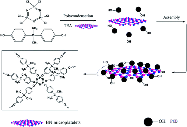
:![[thin space (1/6-em)]](https://www.rsc.org/images/entities/char_2009.gif) 3 = v/v) was ultrasonically mixed for 5 h. Then the sticky and pale yellow suspended solution was magnetic stirred with reflux condensation continuously in an 80 °C oil bath for 72 h. After the treatment, the BN particles were washed with deionized water for several times until the filtered water was neutral, and then dried at 60 °C under vacuum overnight. The treated BN micro-platelets were ground into powder and named as ABN. Next, the ABN particles were coated modification by poly(cyclotriphosphazene-co-bisphenol A) with non-covalent bond. In a 250 ml three-necked flask, ABN particles (2 g) were dispersed in 120 ml acetonitrile solvent dissolved HCCP (0.5 g) and BPA (0.98 g) via ultrasonic dispersion for 10 min to get a homogeneous mixture. Then 2 ml TEA were put into the mixture, followed by reacting at 42 °C in an ultrasound bath (150 W, 40 kHz) for 5 h. Then, the mixture was stirred with a low-speed mechanical stir in order to obtain a suspension liquid. After that the suspension was centrifuged, filtered and washed with absolute ethyl alcohol and deionized water for three times, subsequently dried in a vacuum oven at 80 °C for 24 h. The resultant product was labeled as PCB-BN. The route for synthesizing PCB-BN is illustrated in Fig. 1.
3 = v/v) was ultrasonically mixed for 5 h. Then the sticky and pale yellow suspended solution was magnetic stirred with reflux condensation continuously in an 80 °C oil bath for 72 h. After the treatment, the BN particles were washed with deionized water for several times until the filtered water was neutral, and then dried at 60 °C under vacuum overnight. The treated BN micro-platelets were ground into powder and named as ABN. Next, the ABN particles were coated modification by poly(cyclotriphosphazene-co-bisphenol A) with non-covalent bond. In a 250 ml three-necked flask, ABN particles (2 g) were dispersed in 120 ml acetonitrile solvent dissolved HCCP (0.5 g) and BPA (0.98 g) via ultrasonic dispersion for 10 min to get a homogeneous mixture. Then 2 ml TEA were put into the mixture, followed by reacting at 42 °C in an ultrasound bath (150 W, 40 kHz) for 5 h. Then, the mixture was stirred with a low-speed mechanical stir in order to obtain a suspension liquid. After that the suspension was centrifuged, filtered and washed with absolute ethyl alcohol and deionized water for three times, subsequently dried in a vacuum oven at 80 °C for 24 h. The resultant product was labeled as PCB-BN. The route for synthesizing PCB-BN is illustrated in Fig. 1.
2.3. Preparation of EP/PCB-BN composites
The EP/PCB-BN composites were prepared by solution blending and casting method. Firstly, 25 g epoxy resin (WSR 618) was added to a 250 ml three-necked flask, and then stirred, degassed in vacuum drying oven at 80 °C for 30 min. The homogeneous solution was cooled to room temperature, and then desired amounts of PCB-BN (0, 5, 10, 20 wt% based on the weight of EP), 21.25 g curing agent (MeTHPA) and 0.5 g catalyst (DMP-30) were added to epoxy resin step by step. Secondly, the mixture was vigorously stirred and ultrasonically dispersed at 40 °C for 60 min. Then, the mixture was poured into preheated stainless steel mold and degassed until no air bubbles appeared. The composites were cured at 80 °C for 2 h in an oven and post-cured at 150 °C for 4 h.2.4. Characterization
Fourier-transform infrared (FT-IR) spectrum was conducted with a Bruker Vector-22 FTIR spectrometer instrument over the range of 4000–400 cm−1. Thermal gravimetric analyses (TGA) were performed with a SDT Q600 instrument at a heating rate of 20 °C min−1 under nitrogen atmosphere or air atmosphere. The crystalline structures of boron nitride were identified by SmartLab X-ray diffraction patterns (XRD) with Cu Kα radiation. The morphologies of PCB-BN, and dispersion of fillers in the epoxy matrix were investigated by the scanning electron microscopy (FE-SEM, Nova Nano SEM 450, FEI). Meanwhile, the energy-dispersive X-ray spectroscopy (EDAX, Octane Plus) analysis was used to study the boron element mapping on the surfaces of the fractured EP/PCB-BN or EP/BN composites operated on the same SEM instruction. The thermal conductivity of neat epoxy and its composites at room temperature were measured by TC 3000 Series Thermal Conductivity Apparatus (Xi'an Xiatech Electronic Technology Co., China) based on transient hot-wire technique. The widely used transient hot-wire technique is an accurate, reliable and fast method to determine thermal conductivity of gases, liquids, and solids without convective errors.40 In this method, a thin metallic wire, as a line heat source and temperature sensor, is suspended between two flat testing samples. When the wire temperature is raised by a constant heat flux, it conducts heat to the surrounding medium, i.e. testing samples. The rate of heat transfer associated with the thermal conductivity of surrounding materials, is reflected by the temperature changes of the wire. Thus, the thermal conductivity λ of testing medium, neat epoxy and its composite samples is calculated by:
 | (1) |
The ultrahigh electric resistor (ZC36, Shanghai Sixth Electric Meter Factory, China) was used to measure volume and surface resistivity of the epoxy composites at room temperature. The voltage applied on test samples was 250 V or 1000 V. Micro combustion calorimeter (MCC) test was used to evaluate the fire retardancy properties of the epoxy and its composites using a FTT0001 micro-scale combustion calorimetry (FTT Co., U.K.).
3. Results and discussion
3.1. Synthesis and characterization of PCB-BN
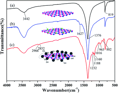
The synthesis of PCB-BN is based on ring cross-linked of HCCP organic–inorganic micro–nano hybrid polymer materials. It can be simply and reliably adsorbed on a variety of high surface energy substrate surface by the way of template-induced self-assembly, and then the surface functional modification of base materials can be achieved, as shown in Fig. 1. In the polar C2H3N solvent, the reaction of HCCP and BPA was made by a condensation polymerization with the acid-binding agent (TEA). In the early reaction stage, the polymerization produced a large number of nanoscale particles and small molecule byproduct (HCl), which was captured by triethylamine to accelerate the polymerization process. The generated primary nanoparticles had very high surface energy, a tendency spontaneously to spread over on the substances with high surface energy.41 Then, the active particles would continue to adsorb-assemble on the surface of BN and form large particle aggregates. So as the reaction proceeds, the particles adhered onto the surface of the BN will be further cross-linking connected to each other under mild external conditions, thus achieving the poly(cyclotriphosphazene-co-bisphenol A) (PCB) non-covalent surface modification of BN.The FTIR spectra of BN, ABN and PCB-BN particles are as shown in Fig. 2. In Fig. 2a, the characteristic B–N stretch and bending peaks at 1376 cm−1 and 819 cm−1, the hydroxyl groups and amino groups at the edge planes of BN at 3442 cm−1 are observed.42,43 As can be seen from Fig. 2b, the hydroxyl groups at 3442 cm−1 becomes much stronger after the BN particles are treated with mixed strong acids. In addition, two new weak peaks appeared at 1627 cm−1 and 1717 cm−1. Compared with that of BN, many significant new peaks can be observed on the spectrum of PCB-BN, shown in Fig. 2c. Bands at 2966 cm−1 and 2852 cm−1 belonged to the asymmetric and symmetric –CH2– stretching vibrations. The peaks at 1160 cm−1 and 1016 cm−1 were assigned to C–O stretching connection benzene ring. The peak at 1232 cm−1 and 882 cm−1 were associated with the stretching vibration of P–N group in the cyclotriphosphazene structure. The peak at 1188 cm−1 was ascribed to the P![[double bond, length as m-dash]](https://www.rsc.org/images/entities/char_e001.gif) N stretching vibration, which indicated that PCB-BN kept the skeleton structure of cyclotriphosphazene.44,45 Meanwhile, the new intensive absorption at 965 cm−1 was associated with P–O–Ph band,46 which was an obvious evidence of copolymerization of HCCP and BPA on the surfaces of BN particles.
N stretching vibration, which indicated that PCB-BN kept the skeleton structure of cyclotriphosphazene.44,45 Meanwhile, the new intensive absorption at 965 cm−1 was associated with P–O–Ph band,46 which was an obvious evidence of copolymerization of HCCP and BPA on the surfaces of BN particles.
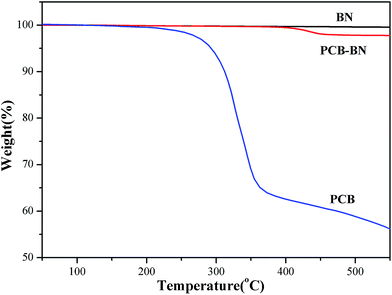
The TGA curves of BN, PCB and PCB-BN are presented in Fig. 3. Obviously, with increasing of the temperature, raw BN showed no weight loss at a temperature up to 800 °C, and this stated that raw BN had high thermal stability. Simultaneously, the pure PCB sample began to lose its weight at about 223 °C and degraded in the range of 250–400 °C with around 35% weight loss,47 whereas that of the PCB-BN composite was higher than 400 °C, indicating that phosphazene polymer formed by HCCP and BPA had very high thermal stability. This was because that the polyphosphazene coating layer of PCB-BN surface possessed highly cross-link polymer structures and a large number of the polyphosphazene rings. The phosphazenes ring itself had excellent thermal stability. At the same time, the thickness of the coated layer of PCB-BN could be controlled by changing the ratio of the co-monomer and reaction conditions. In order to avoid excessive coating layer on PCB-BN surfaces as it would influence the thermal resistance and thermal conductivity of the composites, the surface coating volume should be controlled at about 2 wt%.
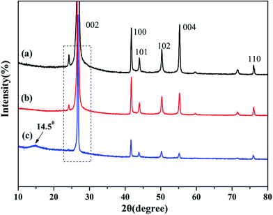
XRD is known to be a useful technique to characterize the crystallite size and there-dimensional order of materials. Fig. 4 shows the XRD patterns of as-received BN, ABN and PCB-BN. All samples showed similar XRD patterns, and the diffraction peaks corresponded to (002), (100), (101), (102), (004) and (110) planes of the hexagonal crystal of boron nitride from 10° to 80°, respectively (JCPDS ICSD 34-0421).48 The diffraction peak intensity for (102) plane was relatively higher, which meant that the raw BN and its modified patterns had a perfectly ordered structure and degree of graphitization.49 Besides, no new peak appeared after BN modification, notably, the positions of these main peaks did not change, but the peak's width of PCB-BN became narrow, and the intensity became weaker compared with the pattern of BN, suggesting that HCCP non-covalent surface modified BN had a different order structure. And it was also found that a diffuse amorphous peak at 2θ = 14.5°, was the diffraction peak of polyphosphazene on the surface of BN. Furthermore, the interlayer distance (d002) and the thickness along the c axis (Lc) were calculated by Bragg equation and Scherrer formula (the calculation results see Table 1).
2d![[thin space (1/6-em)]](https://www.rsc.org/images/entities/char_2009.gif) sin sin![[thin space (1/6-em)]](https://www.rsc.org/images/entities/char_2009.gif) θ = nλ θ = nλ
| (2) |
 | (3) |
| Sample | 2θ (°) | d002 (nm) | Lc (nm) |
|---|---|---|---|
| BN | 26.89 | 0.3312 | 29.16 |
| ABN | 26.86 | 0.3315 | 28.05 |
| PCB-BN | 26.77 | 0.3326 | 30.25 |
It can be seen, compared with BN, the 2θ becomes smaller, d002 and Lc were slightly larger than that of PCB-BN, suggesting polyphosphazene intercalation was not obvious and the exfoliation barely appeared during the synthesis process of PCB-BN.
Fig. 5 shows the SEM images of BN and PCB-BN particles. It is clear to see that the 001 basal plane is very smooth and almost has no uneven edges (Fig. 5a). An interesting phenomenon was found that the surface of PCB-BN modified by poly(cyclotriphosphazene-co-bisphenol A) becomes rough (Fig. 5b and c). The organic modified surfaces of BN particles would decrease its surface energy, and improved the interfacial binding with the organic matrix for the EP/PCB-BN composites.
3.2. Thermal conductivity of the composites
The thermal conductivity of neat epoxy and epoxy composites was measured by the transient hot-wire method at room temperature. Fig. 6 compares the thermal conductivity of epoxy composites prepared with different contents of the BN fillers and PCB-BN fillers. The thermally conductive polymer filled with inorganic filler was mainly dependent on the filler lattice phonon vibration and then interfacial binding force between the filler and the matrix. The thermal conductivity of boron nitride along the basal plane (001) is up to 300 W m−1 K−1, while the thermal conductivity of pure epoxy is 0.192 W m−1 K−1. So it was crucially important that BN particles contacted with each other and form thermally conductive pathways for the composites to improve thermal conductivity. It could be seen that the thermal conductivity of the composites was improved, as the mass fraction of BN and PCB-BN increased. At the low mass fractions, BN particles were randomly embedded in the epoxy matrix with no contact. The thermal conductivity of the composite material was still mainly dependent on the polymeric segments vibration, so in this case the thermal conductivity was very low. With increased loading level of BN fillers, BN particles could sufficiently contact and easily form sectional thermally conductive pathways and networks, leading to higher thermal conductivity. When the loading of BN fillers was 20 wt%, the thermal conductivity of the composites reached to 0.644 W m−1 K−1. However the thermal conductivity of composites filled PCB-BN particles increased to 0.708 W m−1 K−1, which was 3.7 times higher than that of pure epoxy resin.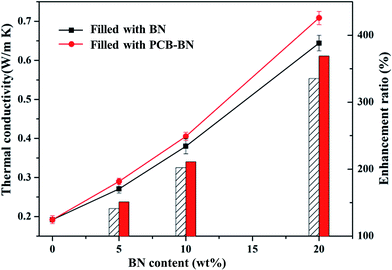 | ||
| Fig. 6 Thermal conductivity of the epoxy composites as a function of BN content (the line represents the thermal conductivity, the bar represents the enhancement ratio). | ||
The thermal conductivity of EP/PCB-BN composites was higher than that of EP/BN ones. This was closely related to the dispersity of fillers in matrix and the interface bonding force between fillers and matrix. The interface phonon scattering caused by the filler–polymer interface thermal resistance and the phonon–phonon scattering caused by the filler–filler contact thermal resistance were the reasons why thermal conductivity of the composites is reduced. The PCB-BN particles modified by poly(cyclotriphosphazene-co-bisphenol A), the BPA molecular chain on the filler surfaces and that of the epoxy matrix diffused and occurred entangle with each other, and increased the number of physical crosslinking point of the filler in the matrix. This resulted in the excellent interface bond to improve the thermal conductivity by decreasing phonon scattering. Simultaneously, this functionalization on the surface of BN particles could prevent particles' agglomeration, and it was beneficial to improve the homogeneous dispersion of BN fillers in matrix. The morphology images are as shown in Fig. 7. Fig. 7a shows that fracture surface of neat epoxy is very smooth and the shape of crack propagation appears as river patterns, which is a typical feature of brittle fracture.51 All composites exhibited a wrinkled rough fracture surface, and the BN particles were randomly exposed or embedded in epoxy matrix. This phenomenon was due to the local polymer deformation or matrix shear yielding, which could be explained by a crack deflection mechanism caused by adding BN fillers.51,52 For 10 wt% raw BN-filled composites (Fig. 7b), owing to the poor wettability and high surface energy of BN platelets, large embedded microplatelets form agglomerated bundles and cause voids on the fracture surface, indicating weak interfacial adhesion between fillers and matrix. Poor dispersion state may have caused a decrease in phonon mean free path due to structure boundary scattering and defect scattering,42 meaning an inefficient heat transfer. The surface of the modified BN platelets exhibits desirable homogeneity and dispersion in the epoxy composite (Fig. 7c), and the regions of agglomeration and voids can not be observed, even at higher addition of fillers (20 wt%, Fig. 7d). This was because the enhanced interfacial compatibility of the surface modified BN particles and epoxy assisted in good dispersion of PCB-BN particles in the matrix. Moreover, the polyphosphazene, encapsulated on the BN surface, interfered with interparticles attractions, thereby hindering agglomeration of the particles. Such uniform dispersion and good compatibility were beneficial to the formation of efficient thermally conductive networks.
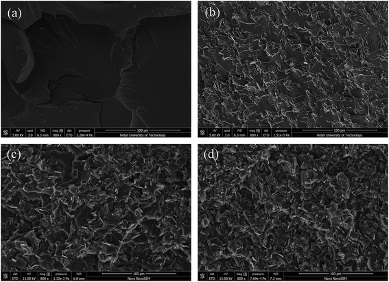 | ||
| Fig. 7 SEM images of the fractured surface of epoxy resin and its composites: (a) neat epoxy, (b) EP/10 wt% BN composite, (c) EP/10 wt% PCB-BN composite, (d) EP/20 wt% PCB-BN composite. | ||
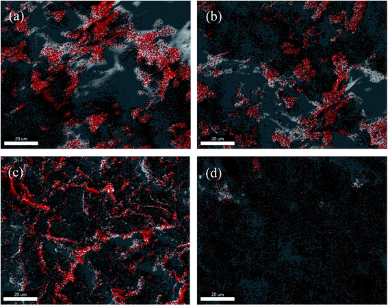
In order to examine the exact distribution of BN particles in epoxy matrix, boron (B, in red color) element mapping is performed through energy-dispersive X-ray spectroscopy (EDS), as shown in Fig. 8. The distribution of B (BN) element in EP/BN composite is non-uniform, when the BN particles are unmodified (Fig. 8a). The interfacial tension between BN particle and epoxy matrix was big, and the aggregation of the filler was obvious. After the BN particles are encapsulated with polyphosphazenes (PCB), their dispersity in epoxy matrix are improved to some extent when the PCB-BN content is 5 wt% (Fig. 8b). Further addition of PCB-BN particles, even to 20 wt%, the dispersion of BN in composites are homogenous, as shown in Fig. 8c and d. These results were consistent with SEM observation and the enhancement of thermal conductivity, discussed as below.
3.3. Electrical insulation properties of the composites
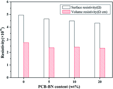
Electrical insulation property is a key factor critical to the thermal management application and microelectronic packaging. Materials with high electrical insulation can ensure the security and stability of the electronic components when they operate in electric field. Fig. 9 presents the surface and volume resistivity of the neat epoxy and fabricated composites as a function of PCB-BN content. The surface resistivity slightly decreased with the addition of PCB-BN fillers, whereas the volume resistivity still maintained almost the same level as the neat epoxy. After applying a voltage of 250 V, the surface and volume resistivity of 20 wt% modified BN-filled composites were 4.32 × 10¹⁶ Ω and 2.33 × 10¹⁶ Ω cm, and for the neat epoxy were 4.95 × 10¹⁶ Ω and 2.77 × 10¹⁶ Ω cm, respectively. In addition, all the test samples showed no dielectric breakdown even at the 1000 V applied electric field, i.e., the maximum voltage of the tester. The composites prepared in this study retained good electrical insulation properties, because of the inherent electrical insulating characteristic of the PCB-BN fillers and epoxy.53 These epoxy/PCB-BN composites possessed desirable properties for packaging materials that required electronic insulators with high thermal conductivity.543.4. Thermal stability of the composites
The TGA and DTG curves for the neat epoxy and EP/PCB-BN composites under nitrogen atmosphere are shown in Fig. 10. Table 2 summarizes the temperature for 10% weight loss (T10%), 50% weight loss (T50%), maximum degradation temperature (Tmax) and the char yield under 800 °C of all the samples. It revealed that the thermal degradation temperature of all samples were one step between 350 °C and 450 °C under nitrogen, showing the fracture of epoxy crosslink network. The inserted enlarged figure displays that the T10% and T50% of the EP/5 wt% PCB-BN composites are 397.3 °C and 431.7 °C, which increases 19.3 °C and 6.3 °C in comparison with neat epoxy, respectively. The T10% and T50% of the composites decreased gradually with the increase of the PCB-BN particle content, but the T10% values of the composites were still higher than that of neat epoxy. This phenomenon could be explained by factors in the following two aspects. First, two-dimensional layered structure PCB-BN micro-platelets could form good mass transfer barrier layer, the so-called “tortuous path” constituted by BN may delay the permeation and escape of volatile degradation products.55 PCB-BN particles simultaneously acted as physical crosslinking points in the matrix, in which would improve thermal stability of the composites. Secondly, in the degradation process, the polyphosphazene on the surface of BN particles could produce phosphoric acid and metaphosphoric acid, capture the hydroxyl of epoxy, promote the accelerated decomposition of the epoxy matrix so as to better form dense carbon layer instead of generating volatile gases.56 It is also noted from Table 2 that the char yield of the composites with addition of 5%, 10% and 20% PCB-BN particles under 800 °C have been increased to 13.54%, 20.64% and 29.66%, respectively. This illustrated that the addition of PCB-BN was helpful to improve the carbon forming process of epoxy resin. The carbon layer was beneficial to prevent heat diffusion and heat transfer, and then reduce the decomposition temperature of flammable materials and effectively hinder further combustion of materials.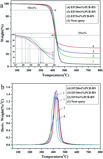 | ||
| Fig. 10 (a) TG and (b) DTG curves of the EP/PCB-BN composites (the insert of TG curve showing the enlarged temperature ranging from 360 °C to 460 °C, in order to observe the T10% and T50%). | ||
| Sample | T10% (°C) | T50% (°C) | Tmax (°C) | Ycat 800°C (%) |
|---|---|---|---|---|
| Neat epoxy | 378.0 | 425.4 | 423.8 | 3.68 |
| EP/5 wt% PCB-BN | 397.3 | 431.7 | 426.1 | 13.54 |
| EP/10 wt% PCB-BN | 392.4 | 426.3 | 417.2 | 20.64 |
| EP/20 wt% PCB-BN | 386.0 | 421.0 | 406.6 | 29.66 |
To better understand the above views, further experiments were carried out. We study the residue char layer morphology of neat epoxy and EP/5 wt% PCB-BN composites after TG test, as shown in Fig. 11. It is noted that pure epoxy carbon layer structure is very loose after burning (Fig. 10a) and the surface exists some voids and cracks, which provides the access to oxygen and heat transfer. Thus it could not hinder the further burning of material inside. While the EP/5 wt% PCB-BN composite char layer was relatively smooth, compact in structure and basically free of any voids. This was caused by the polyphosphazene decomposition on the surface of PCB-BN particles prompting epoxy matrix decomposition into char, which not only cut off heat and combustible gas transfer and spread into polymer, but also prevented internal polymer from being degraded further and the flammable materials from being migrated to the surface,57 thereby enhancing the flame retardant property of the composites.
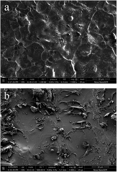 | ||
| Fig. 11 SEM images of the char residues for (a) neat epoxy and (b) EP/5 wt% PCB-BN composite after TG testing. | ||
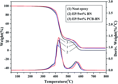
Fig. 12 shows TG and DTG curves of neat epoxy and the epoxy composites in an air atmosphere. Compared with the results obtained in the nitrogen atmosphere, the TG curves of all samples contain two thermal degradation stages divided by two DTG peaks. In the later thermal degradation stage, the char layer formed at high temperature degraded further in air. Compared with neat epoxy, T10% and T50% values of the EP/PCB-BN composites increased from 379.1 °C and 432.0 °C of neat epoxy to 395.9 °C and 435.8 °C (Table 3), respectively. It was also noted that the Tmax values of the EP/5 wt% BN and EP/5 wt% PCB-BN composites were 566.1 °C and 573.7 °C, higher than that of the neat epoxy. This was due to the addition of BN particles, especially functionalized with polyphosphazene layers, which could promote the rate of epoxy resin char. The char layer could protect the internally epoxy and delay the degradation rate, and then improve the stability of the composites at high temperature. In addition, the epoxy resin almost completely degraded at 800 °C, whereas EP/5 wt% PCB-BN composites had char yield of 5.43%, higher than the value 4.72% of EP/5 wt% BN composites. This was indicated that no matter in nitrogen atmosphere or air atmosphere, the addition of PCB-BN to epoxy resin could promote the char formation of system, and improve the thermal stability and flame retardant property of composites.
| Sample | T10% (°C) | T50% (°C) | Tmax (°C) | Ycat 800°C (%) | |
|---|---|---|---|---|---|
| Tmax1 (°C) | Tmax2 (°C) | ||||
| Neat epoxy | 379.1 | 432.0 | 421.2 | 561.8 | 0.00 |
| EP/5 wt% BN | 386.5 | 433.5 | 431.8 | 566.1 | 4.72 |
| EP/5 wt% PCB-BN | 395.9 | 435.8 | 424.6 | 573.7 | 5.43 |
3.5. Flame retardant property of the composites
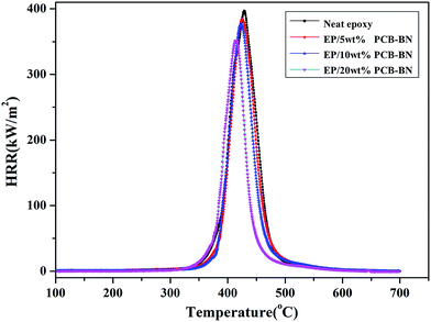
Micro combustion calorimeter (MCC) is a useful technique to study the relationship between polymer chemical structure and combustion behavior based on oxygen consumption theory.58 Fig. 13 shows the heat release rate (HRR) curves of the epoxy resin and its composites, and Table 4 summarizes the relevant parameters obtained from MCC test, such as peak heat release rate (PHRR), the time of peak heat release rate (TPHRR), total heat release rate (THR) and heat release capacity (HRC). It could be seen that the peak of epoxy HRR curve was sharp, the PHRR value was 397.1 w/g, and the PHRR of composites gradually decreased with increasing of PCB-BN content. This was related to the barrier action of PCB-BN for cracking gas.59 PCB-BN particles possessed a large aspect ratio and slice layer barriers played an important role in hindering heat transfer and gas diffusion. What's important was that the polyphosphazene on PCB-BN surface could promote the rate of epoxy resin decomposed into char. The char layer could restrain heat transfer to internal matrix and reduce evaporation of the combustible gas, thereby improving the flame retardant property of composites to a certain extent.55 On the other hand, THR responsed the amount of released heat in the combustion process parameter and was another important parameter that evaluated the fire safety.60 The THR value of neat epoxy was the highest (22.9 kJ g−1), whereas the values of the composites gradually decreased. At the same time, the TPHRR was arrived early, and the HRC decreased also. The above parameters of all EP/PCB-BN composites were lower than the corresponding values of EP resin, and the reduced degree increased as the PCB-BN content increased. With the addition of 20 wt% PCB/BN, the PHRR, TPHRR, THR, and HRC values changed to 88.6%, 96.6%, 75.5%, and 87.8% of those of epoxy resin, respectively, demonstrating that the addition of PCB-BN could effectively improve the flame retardancy of the epoxy resin. The possible reasons may be that the thermal decomposition of the containing-phosphazene compounds was an endothermic process, and phosphate, metaphosphate, polyphosphazene generated in the thermal decomposition formed a nonvolatile protective film on the surface of the polymer to isolate it from the air; meanwhile, the non-flammable gases released such as CO2, NH3 and N2 cut off the supply of oxygen so as to achieve the aims of synergistic flame retardancy.39,56| Sample | PHRR (w/g) | TPHRR (°C) | THR (kJ g−1) | HRC (J g−1 K−1) |
|---|---|---|---|---|
| Neat epoxy | 397.1 | 426.8 | 22.9 | 400 |
| EP/5 wt% PCB-BN | 384.2 | 426.4 | 21.2 | 382 |
| EP/10 wt% PCB-BN | 377.2 | 422.9 | 19.7 | 376 |
| EP/20 wt% PCB-BN | 352.0 | 412.4 | 17.3 | 351 |
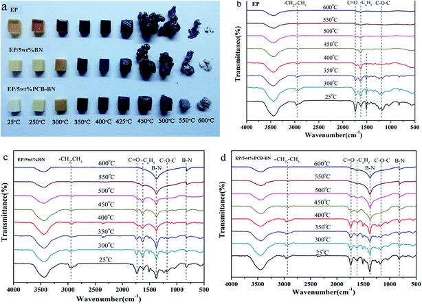
In order to further study the morphology change during heating, the neat epoxy and its composites are heated to the preset temperatures and maintained for 10 min in a muffle furnace, as shown in Fig. 14a. The heating transfer mechanism in a muffle furnace was thermal radiation, and the heating was uniform. Therefore, it had been generally accepted that the thermal oxide stability of a polymer was closely related to the flame retardancy and high thermal oxide stability was very important for developing flame retardant materials. It could be seen that, with the increase of the temperature the colors of all samples gradually deepened to black after 400 °C, indicating occurred charring of surface. Epoxy resin and EP/5 wt% BN composite could not retain their shapes and their volumes rapidly expanded two or three times after the temperature was higher than 450 °C. The resins had been seriously damaged in the heating process. It was worth noting that the mass of epoxy resin significantly decreased as the heating temperature increased. Furthermore, it became hollow when the temperature was higher than 450 °C. The inside matrix resin was migrated to the outside and the entire sample was fluffy, leading to the resin easily collapsed. For epoxy resin, the residual mass was very little when the temperature is 600 °C. It can be also found from FTIR spectra in Fig. 14b that no peak attributing to organic groups can be observed after the temperature is higher than 450 °C. The EP/5 wt% BN composite showed a similar phenomenon compared to neat epoxy, but the volume expansion was not as large as that of epoxy. While there was a strange phenomenon that a layer of white substance appeared on the surface of the composite char when the temperature was higher than 550 °C, especially at 600 °C. At the same time, the –B–N– bonds stretching vibration and bending vibration peaks appear obviously in the FTIR spectra (Fig. 14c). This proved that the white substance was BN. The addition of BN could delay degradation speed of organic functional groups with the increase of the temperature. In summary, the char layers generated in degradation process of neat epoxy and EP/5 wt% BN composite were not enough compact and thus can not protect the internal resin degradation.
The EP/5 wt% PCB-BN composite showed an excellent dimensional stability during the whole experiment. The volume of EP/5 wt% PCB-BN composite almost had no expansion and still maintained the original shape. The char surface was smooth and compact. The formation of the char in the decomposition of cyclotriphosphazene-containing PCB-BN compounds not only increased the weight-loss temperature of epoxy matrix in the high-temperature region, but also resulted in a high char yield. The protective char could isolate the oxygen in the air and the heat away from the polymer matrix, holding back the decomposing molecule from transport onto the surface to be exposed to the heat. Furthermore, its weight loss was lower than those of epoxy and EP/5 wt% BN composite at the same temperature. This revealed that the addition of PCB-BN could form a cross-linked network with excellent thermal and dimensional stability, and the structure could protect the internal resin from further degradation.61 It is confirmed by the FTIR spectra (Fig. 14d). The existence of C![[double bond, length as m-dash]](https://www.rsc.org/images/entities/char_e001.gif) O and C6H5 functional groups demonstrates that the addition of PCB-BN can avoid the matrix resin from being completely degraded and effectively improve the flame retardant property.
O and C6H5 functional groups demonstrates that the addition of PCB-BN can avoid the matrix resin from being completely degraded and effectively improve the flame retardant property.
4. Conclusions
Thermally conductive composites with different BN contents were successfully fabricated from polyphosphazene-coated BN particles embedded in the epoxy matrix. FTIR, TGA, XRD and SEM observation demonstrated that polyphosphazene was successfully coated on the surfaces of BN particles. The thermal conductivity of embedded PCB-BN gave the epoxy composites a superior thermal transport performance. The thermal conductivity was 0.708 W m−1 K−1 with loading of 20 wt% PCB-BN particles, 3.7 times higher than that of the neat epoxy. In addition, the composites possessed excellent electrical insulation and thermal stability. The polyphosphazene released from PCB-BN made the composites prefer to form dense and thermally stable char, resulting in effectively improved flame retardant property. The present epoxy/PCB-BN composites, equipped with high thermal conductivity, fine flame retardant, and excellent electrical insulation property, offered great potential for thermal management application and microelectronic encapsulation.Acknowledgements
This work was financially supported by Natural Science Foundation of Hebei Province (contact no. E2016202036, E2014202033), National Natural Science Foundation of China (contact no. 51573037), Program for Changjiang Scholars and Innovative Research Team in University (IRT13060) and Key Lab for Micro- and Nano-Scale Boron Nitride Materials in Hebei Province.References
- C. Zhi, Y. Bo, C. Tang, K. Hiroaki and G. Dimitri, Adv. Mater., 2009, 21, 2889 CrossRef CAS.
- H. Yurdakul, Y. Goncu, O. Durukan, A. Akay, A. T. Seyhan and N. Ay, et al., Ceram. Int., 2012, 38, 2187 CrossRef CAS.
- S. De, A. Willand, M. Amsler, P. Pochet, L. Genovese and S. Goedecker, Phys. Rev. Lett., 2011, 106, 508 CrossRef PubMed.
- Y. Lin, T. V. Williams and J. W. Connell, J. Phys. Chem. Lett., 2009, 1, 277 CrossRef.
- D. Golberg, Y. Bando, Y. Huang, T. Terao, M. Mitome and C. H. Tang, et al., ACS Nano, 2010, 4, 2979 CrossRef CAS PubMed.
- S. Madakbas, E. Cakmakcl and M. V. Kahraman, Thermochim. Acta, 2013, 552, 1 CrossRef CAS.
- T. Sainsbury, A. Satti, P. May, Z. Wang, I. McGovern and Y. K. Gun'ko, et al., J. Am. Chem. Soc., 2012, 134, 60 CrossRef PubMed.
- J. Eichler and C. Lesniak, J. Eur. Ceram. Soc., 2008, 28, 1105 CrossRef CAS.
- C. Harrison, S. Weaver, C. Bertelsen, E. Burgett, N. Hertel and E. Grulke, J. Appl. Polym. Sci., 2008, 109, 2529 CrossRef CAS.
- W. L. Song, P. Wang, L. Cao, A. Anderson, M. Meziani and A. J. Farr, et al., Angew. Chem., Int. Ed., 2012, 51, 6498 CrossRef CAS PubMed.
- M. H. Tsai, I. H. Tseng and J. C. Chiang, et al., ACS Appl. Mater. Interfaces, 2014, 6, 8639 CAS.
- H. Yu, L. Li and T. Kido, et al., J. Appl. Polym. Sci., 2012, 124, 669 CrossRef CAS.
- Z. Wang, T. Lizuka and M. Kozako, et al., IEEE Trans. Dielectr. Electr. Insul., 2011, 18, 1963 CrossRef CAS.
- J. Gu, Q. Zhang and J. Dang, Polym. Adv. Technol., 2012, 23, 1025 CrossRef CAS.
- K. Kim, M. Kim, Y. Hwang and J. Kim, Ceram. Int., 2014, 40, 2047 CrossRef CAS.
- X. Zeng, S. Yu and R. Sun, J. Appl. Polym. Sci., 2013, 128, 1353 CAS.
- C. C. Teng, C. C. M. Ma, K. C. Chiou, T. M. Lee and Y. F. Shih, Mater. Chem. Phys., 2011, 126, 722 CrossRef CAS.
- K. Kim and J. Kim, Ceram. Int., 2014, 40, 5181 CrossRef CAS.
- J. Yu, H. Mo and P. Jiang, Polym. Adv. Technol., 2015, 26, 514 CrossRef CAS.
- M. T. Huang and H. Ishida, Surf. Interface Anal., 2005, 37, 621 CrossRef CAS.
- K. Kim, M. Kim and J. Kim, Compos. Sci. Technol., 2014, 103, 72 CrossRef CAS.
- M. Donnay, S. Tzavalas and E. Logakis, Compos. Sci. Technol., 2015, 110, 152 CrossRef CAS.
- H. Yan, Y. Tang, J. Su and X. Yang, Appl. Phys. A: Mater. Sci. Process., 2014, 114, 331 CrossRef CAS.
- T. Heid, M. Fréchette and E. David, IEEE Trans. Dielectr. Electr. Insul., 2015, 22, 1176 CrossRef CAS.
- L. Fang, C. Wu, R. Qian, L. Xie, K. Yang and P. Jiang, RSC Adv., 2014, 4, 21010 RSC.
- T. Huang, X. Zeng, Y. Yao, R. Sun, F. Meng, J. Xu and C. Wong, RSC Adv., 2016, 6, 35847 RSC.
- K. S. Kim, M. B. Jakubinek, Y. Martinez-Rubi, B. Ashrafi, J. Guan, K. O'Neill, M. Plunkett, A. Hrdina, S. Lin, S. Dénommée, C. Kingston and B. Simard, RSC Adv., 2015, 5, 41186 RSC.
- Ü. Tugay, E. Volkan and A. Ahmet, Compos. Struct., 2016, 150, 124 CrossRef.
- A. D. Kelkar, Q. Tian, D. Yu and L. Zhang, Mater. Chem. Phys., 2016, 176, 136 CrossRef CAS.
- K. Gaska, A. Rybak, C. Kapusta, R. Sekula and A. Siwek, Polym. Adv. Technol., 2015, 26, 26 CrossRef CAS.
- Z. Wang, Y. Fu, W. Meng and C. Zhi, Nanoscale Res. Lett., 2014, 9, 1 CrossRef PubMed.
- X. B. Wang, Q. Weng, X. Wang, X. Li, J. Zhang, F. Liu, X. F. Jiang, H. Guo, N. Xu, D. Golberg and Y. Bando, ACS Nano, 2014, 8, 9081 CrossRef CAS PubMed.
- X. Zeng, Y. Yao, Z. Gong, F. Wang, R. Sun, J. Xu and C. Wong, Small, 2015, 11, 6205 CrossRef CAS PubMed.
- Z. Lin, A. Mcnamara, Y. Liu, K. Moon and C. Wong, Compos. Sci. Technol., 2014, 90, 123 CrossRef CAS.
- F. Wang, Y. Yao, X. Zeng, T. Huang, R. Sun, J. Xu and C. Wong, RSC Adv., 2016, 6, 41630 RSC.
- K. Kim and J. Kim, Int. J. Therm. Sci., 2016, 100, 29 CrossRef CAS.
- H. L. Lee, O. H. Kwon, S. M. Ha, B. G. Kim, Y. S. Kim and J. C. Won, Phys. Chem. Chem. Phys., 2014, 16, 20041 RSC.
- S. Nagaoka, T. Jodai, Y. Kameyama, M. Horikawa, T. Shirosaki, N. Ryu, M. Takafuji, H. Sakurai and H. Ihara, RSC Adv., 2016, 6, 33036 RSC.
- M. E. Gouri, A. E. Bachiri and S. E. Hegazi, et al., Polym. Degrad. Stab., 2009, 94, 2101–2106 CrossRef.
- W. Yu and S. U. S. Choi, Rev. Sci. Instrum., 2006, 77, 076102 CrossRef.
- J. Fu, X. B. Huang, Y. W. Huang, Y. Pan, Y. Zhu and X. Z. Tang, J. Phys. Chem. C, 2008, 112, 16840 CAS.
- J. Yu, X. Y. Huang, C. Wu, X. F. Wu, G. L. Wang and P. K. Jiang, Polymer, 2012, 53, 471 CrossRef CAS.
- T. H. Ferreira, D. C. F. Soares, L. M. C. Moreira, P. R. O. Silva, R. G. Santos and E. M. B. Sousa, Mater. Sci. Eng., C, 2013, 33, 4616 CrossRef CAS PubMed.
- W. Wei, X. B. Huang, X. L. Zhao, P. Zhang and X. Z. Tang, Chem. Commun., 2010, 46, 487 RSC.
- M. Modesti, L. Zanella, A. Lorenzetti, R. Bertani and M. Gleria, Polym. Degrad. Stab., 2005, 87, 287 CrossRef CAS.
- Y. Zhu, X. Huang, W. Li, J. Fu and X. Tang, Mater. Lett., 2008, 62, 1389 CrossRef CAS.
- C. Chen, X. Liu, Z. Tian and H. R. Allcock, Macromolecules, 2012, 45, 9085 CrossRef CAS.
- M. Du, Y. Wu and X. Hao, CrystEngComm, 2013, 15, 1782 RSC.
- Y. M. Xue, A. Elsanousi, Y. Fan, J. Lin, X. W. Xu and Y. Lu, Solid State Sci., 2013, 24, 1 CrossRef CAS.
- X. B. Huang, W. Wei, X. L. Zhao and X. Z. Tang, Chem. Commun., 2010, 46, 8848 RSC.
- L. M. McGrath, R. S. Parnas, S. H. King, J. L. Schroeder, D. A. Fischer and J. L. Lenhart, Polymer, 2008, 49, 999 CrossRef CAS.
- B. Wetzel, F. Haupert and M. Q. Zhang, Compos. Sci. Technol., 2003, 63, 2055 CrossRef CAS.
- J. Hou, G. Li, N. Yang, L. Qin, M. Grami, Q. Zhang, N. Wang and X. Qu, RSC Adv., 2014, 4, 44282 RSC.
- Y. He, Q. Wang, W. Liu and Y. Liu, Phys. Status Solidi A, 2014, 211, 677 CrossRef CAS.
- Y. Cao, J. Feng and P. Wu, Carbon, 2010, 48, 3834 CrossRef CAS.
- R. Liu and X. Wang, Polym. Degrad. Stab., 2009, 94, 617 CrossRef CAS.
- Q. Li, P. K. Jiang, Z. P. Su, P. Wei, G. L. Wang and X. Z. Tang, J. Appl. Polym. Sci., 2005, 96, 854 CrossRef CAS.
- A. R. Tripathy, R. J. Farris and W. J. Macknight, Polym. Eng. Sci., 2007, 47, 1536 CAS.
- G. Huang, J. Gao, X. Wang, H. Liang and C. Ge, Mater. Lett., 2012, 66, 187 CrossRef CAS.
- A. P. Mouritz, Z. Mathys and A. G. Gibson, Composites, Part A, 2006, 37, 1040 CrossRef.
- C. Yang, G. Liang, A. Gu and L. Yuan, Ind. Eng. Chem. Res., 2013, 52, 15075 CrossRef CAS.
| This journal is © The Royal Society of Chemistry 2017 |

