 Open Access Article
Creative Commons Attribution 3.0 Unported Licence
Superhydrophobic silica aerogels reinforced with polyacrylonitrile fibers for adsorbing oil from water and oil mixtures†
Mingjia Shi,
Cunguo Tang,
Xudong Yang,
Junling Zhou,
Fei Jia,
Yuxiang Han and
Zhenyu Li *
*
School of Chemical Engineering, Changchun University of Technology, Changchun 130012, P. R. China. E-mail: cclzy2001@163.com; Tel: +86-431-85716328
First published on 16th January 2017
Abstract
Silica aerogels are unique solids with extremely high porosity, transparency and low density. They make excellent adsorbing materials due to their high surface area and three-dimensional reticular structures. However, their fine structures and hydrophilic surfaces make them fragile and impractical for adsorbing oil from water and oil mixtures. To improve their mechanical properties, we incorporate small amounts of polyacrylonitrile fiber into the aerogels, prepared at relatively mild temperatures. Electron microscopy images and pore size distributions of the modified aerogels show that the silica aerogel had a co-continuous porous structure. The aerogels were modified to be superhydrophobic, and the surface hydroxyl or alkoxy groups were converted to stable –CH3 groups with a contact angle as high as 169°. The oil adsorption capacity of the silica aerogels was calculated as 9.56 g/g. The sorption and desorption process could be repeated at least 100 times, indicating that silica aerogels are promising oil-absorbing materials.
Introduction
With a rapid increase in global energy demand, oil production has continued to grow from conventional and unconventional resources. Significant amounts of oil pollutants are generated during these processes.1–5 Discharging wastewater from these processes into the environment has become a significant concern for current oil production techniques such as fracking. Therefore, various techniques have been adopted to remove oil from water and oil mixtures, including adsorption, filtration, reverse osmosis, air flotation, biological processes, chemical coagulation, electro coagulation and electro flotation.6–8 Among these techniques adsorption is the most common and most widely used due to its high efficiency, low cost, and wide adaptability.9–11 Conventional natural materials such as sawdust, zeolite and wool fiber have been extensively used for oil removal due to their porous structures and high surface area.12–14 However, the major drawback of these materials is that water and oil cannot be separately absorbed, and as such their adsorption efficiency is poor. As a result, there is an increasing need for the development of new porous materials to effectively adsorb oil from water.Recently, silica aerogels with low density and high porosity have attracted great research interest because of their high specific surface area and superhydrophobic properties.15–17 Their excellent accessibility to the inner surface through open porous networks leads to unique properties, making them a promising candidate for various applications in wastewater treatment such as adsorbents of toluene, adsorbents of xylenes,18 and adsorbents of heavy metal ions19 and cleanup of oil spills.20,21 Among these potential applications, superhydrophobic silica aerogels can be flexibly utilized as absorbent materials to selectively absorb oil. Effective separation of oil from water is an important challenge for saving endangered environments, especially in cases of marine oil pollution.
Recent studies have established that the incorporation of polymers into silica aerogels is a more promising approach for this behavior because of the mechanical strength enhancement they afford, and the possibility of the polymer imparting hydrophobicity and thermal stability to the silica backbone.22,23 Kanamori25,26 reported ambient pressure-dried, flexible, marshmallow-like aerogels with a bendable feature using methyltrimethoxysilane (MTMS) and dimethyldimethoxysilane (DMDMS) as co-precursors. However, the brittleness limits its non-load-bearing structural applications; recent efforts have been made to produce fiber-reinforced aerogel composites with higher strength.29 Since then, researchers determined the Young models of organic–inorganic hybrid aerogel/wollastonite composites at room temperature, and found that Ti incorporation into inorganic aerogels networks increases their Young's modulus.22 Research by Rao24 indicated that the mechanical strength of ceramic fiber reinforced aerogel insulation composites was greatly increased compared to pure silica aerogels. Meador27 reported the first synthesis of polyimide aerogels cross-linked through a polyhedral oligomeric silsesquioxane, octa(aminophenyl)silsesquioxane (OAPS). Then, cellulose nanocrystals derived from tunicates (t-CNC) were used as reinforcing nanofiller for polyimide aerogels in their study for better moisture resistance, flexibility, and strength.32–34 Proper selection of silane precursors and polymer reinforcements can yield more durable and stronger silica aerogels. Jana28 focused on the use of silane-end-capped urethane prepolymer and chain-extended polyurethane for reinforcement of silica aerogels. They also produced silica gels grown inside the macropores of thermoreversible syndiotactic polystyrene (sPS) gel.30 Shengyang Tao prepared monolithic silica with macroporous skeleton that the maximum absorptive ability can reach 8 times the monolith's weight and materials could be recycled more than 20 times by an easy treatment.43 Xiangli Chen reported porous polymeric composite monoliths with superior performances the adsorption capacities of the porous materials that the maximum adsorption capacity of already-used transformer oil is 4.91 g/g and the sorption and desorption process could be repeated at least 13 times.44
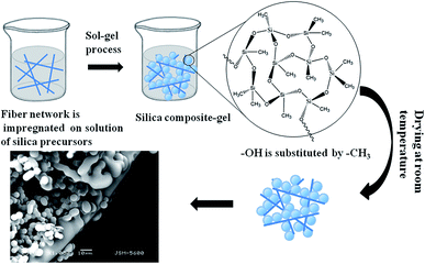
Herein, we report a simple, low-cost, flexible, environmentally-friendly approach for the synthesis and application of silica aerogels capable of separating oil from water in an easy, rapid manner ideal for practical applications. Scheme 1 details the preparation of the polyacrylonitrile fiber reinforced silica aerogels used in this study. This silica aerogel exhibits ideal superhydrophobic and mechanical strength. In the case of silica aerogels, the Si–OH groups at the surfaces of the silica clusters are the main source of hydrophilicity, promoting condensation reactions.35 Our group previously determined that the –Cl in trimethylchlorosilane (TMCS) reacts with –OH to improve the hydrophobicity of the material.31,36 As shown in Scheme 1, the organic silicon source was hydrolyzed at 30 °C. The hydrogel then formed aerogel micro-granules and was aged at 40 °C. Finally, the wet gel was dried at ambient pressure after solvent replacement and modification of the surface hydrophobicity.
Experimental section
Materials
MTMS, DMDMS, N,N-dimethylformamide (DMF), and TMCS were provided by Xiya Reagent. Methanol, acetic acid and isopropanol were purchased from Shenyang Chemical Co. Ltd. Ammonia and n-hexane was purchased from Beijing Chemical Works.Synthesis of polyacrylonitrile fibers
Long polyacrylonitrile fibers were immersed in methanol or ethanol, followed by washing with ultrasonication for 10 min, after which the solution was decanted and placed in an oven to dry. The polyacrylonitrile fibers used in the study is derived from the laboratory preparation. The fibers had a diameter of 10 ± 2 μm and a length of 50 mm.Synthesis of silica aerogel
The silica aerogels was prepared by an acid–base two-step sol–gel method. MTMS (99%), DMDMS (98%), methanol (99%), DMF (99.5%), H2O and acetic acid (99%) were stirred at a molar ratio 1![[thin space (1/6-em)]](https://www.rsc.org/images/entities/char_2009.gif) :
:![[thin space (1/6-em)]](https://www.rsc.org/images/entities/char_2009.gif) 0.7
0.7![[thin space (1/6-em)]](https://www.rsc.org/images/entities/char_2009.gif) :
:![[thin space (1/6-em)]](https://www.rsc.org/images/entities/char_2009.gif) 12
12![[thin space (1/6-em)]](https://www.rsc.org/images/entities/char_2009.gif) :
:![[thin space (1/6-em)]](https://www.rsc.org/images/entities/char_2009.gif) 0.5
0.5![[thin space (1/6-em)]](https://www.rsc.org/images/entities/char_2009.gif) :
:![[thin space (1/6-em)]](https://www.rsc.org/images/entities/char_2009.gif) 40
40![[thin space (1/6-em)]](https://www.rsc.org/images/entities/char_2009.gif) :
:![[thin space (1/6-em)]](https://www.rsc.org/images/entities/char_2009.gif) 7 × 10⁻³ (Fig. S1, S2 and Table S1†) for 1 h at room temperature (approximately 30 °C). NH3·H2O (28%) was added to set the pH of the MTMS stock solution at 8–9 (Fig. S3†) to control the condensation reaction. The prepared polyacrylonitrile fibers were then dispersed in solution and heated at 40 °C to induce gelation. The prepared silica aerogel was placed in isopropyl alcohol for 6 h at 40 °C to remove water and unreacted reagents and to strengthen the aerogel network by aging. 10 vol% TMCS (99.7%)/n-hexane (99%) was added to the wet gel and mixed at 40 °C for 6 h (Fig. S4†). After this time, the residual mixture solution of the modified aerogel was poured out. The pore liquids in the wet gel were exchanged with isopropanol (99%) and n-hexane (99%) at 40 °C for 6 h in a shaker, reducing the surface tension. Finally, the mixture solution was removed and the aerogel was dried at 30 °C under ambient pressure for 12 h to obtain products with different shapes.
7 × 10⁻³ (Fig. S1, S2 and Table S1†) for 1 h at room temperature (approximately 30 °C). NH3·H2O (28%) was added to set the pH of the MTMS stock solution at 8–9 (Fig. S3†) to control the condensation reaction. The prepared polyacrylonitrile fibers were then dispersed in solution and heated at 40 °C to induce gelation. The prepared silica aerogel was placed in isopropyl alcohol for 6 h at 40 °C to remove water and unreacted reagents and to strengthen the aerogel network by aging. 10 vol% TMCS (99.7%)/n-hexane (99%) was added to the wet gel and mixed at 40 °C for 6 h (Fig. S4†). After this time, the residual mixture solution of the modified aerogel was poured out. The pore liquids in the wet gel were exchanged with isopropanol (99%) and n-hexane (99%) at 40 °C for 6 h in a shaker, reducing the surface tension. Finally, the mixture solution was removed and the aerogel was dried at 30 °C under ambient pressure for 12 h to obtain products with different shapes.
Characterization
For all characterizations performed in this study, the fiber contents of the tested samples were 0% and 0.3% (mass fraction) (Fig. S10†).The microstructure of the material was characterized by scanning electron microscopy (SEM), with a JSM-5600LV setup (JEOL, Japan). Prior to SEM imaging, samples were coated with gold through a 2–3 min spraying process under vacuum. The hydrophobicity and surface modification were confirmed by Fourier transform infrared spectroscopy (FTIR). Here, samples were prepared without fibers to prevent the fiber groups from influencing the results. All measurements were performed at room temperature. FT-IR spectra (4000–500 cm−1) in KBr were collected on a Nicolet iS10 (Thermo Fisher, USA) FT-IR spectrometer by a KBr disc method. Contact angles of the aerogels were measured using a sessile method with a contact angle meter (Beijing Hakko test instrument factory, China). Aerogel samples were heat-treated at various temperatures of 30–600 °C in STA 6000 (Perkin Elmer, USA), and illustration thermogravimetric (TG) curves of the aerogel samples were measured to confirm their thermal stability. The mass of each sample was approximately 4 mg. TG analysis (TGA) tests were run at a temperature ramp rate of 10 °C min−1, and under N2 gas flow of 100 mL min−1. The pore volume and macro-porosity of the modified materials were determined using Hg intrusion porosimetry (Micromeritics Autopore IV 9500, USA) in a pressure range of 0.10–30![[thin space (1/6-em)]](https://www.rsc.org/images/entities/char_2009.gif) 000 psi.
000 psi.
The bulk densities (ρb) of the prepared aerogels were calculated as function of on the gel mass-to-volume ratio. The skeletal density (∼1.67 g cm−3) was tested by helium pycnometry, and the porosities were calculated as
The adsorption capacity of the aerogels for various organic solvents and oils was also measured. Aerogels were placed inside the organic liquids for approximately 10 min and then isolated for weight measurements. To avoid evaporation of absorbed organic liquids, weight measurements were performed immediately after adsorption. Each organic liquid was tested three times, and the mean weight gain was reported. To test the reusability, a wet aerogel was squeezed as hard as possible to get rid of the oil absorbed. The monolith was then extruded completely. Finally, there generated porous aerogel was reused and selective adsorption of oil from water.
Compression tests were carried out on the aerogel monoliths in two steps. First, the aerogels were compressed to 80% strain. The test was then stopped and the crosshead was moved back to zero. The specimen was then left to sit for 30 min at room temperature. At that time, the final thickness was measured and the unrecovered strain (%) was determined as the amount of strain still present in the sample relative to the sample's initial length.
Results and discussion
Characterization
Low density aerogel was synthesized (Fig. S5†) at a density of 0.086 g cm−3, and the porosity was calculated as 95%. These density and porosity values clearly indicate that the network structure was maintained after the drying process. The bending and flexibility of the as-prepared aerogel is demonstrated in Fig. S6.†The microstructures of the aerogels reinforced with polyacrylonitrile fiber are indicated by SEM in Fig. 1 (the unmodified aerogels are showed in Fig. S7,† fibers are in Fig. S11†). The diameter of the aerogel particle is mainly distributed between 4.4 and 5.8 μm (Fig. 1c) from the SEM image of the aerogels. The particle size is uniform and the particle surfaces are smooth. The polyacrylonitrile fibers in the aerogel systems are quite effective in increasing the mechanical properties of aerogels. The fibers support the aerogel and decrease the bulk size of the aerogel within the aerogel–fiber matrix composite. Introducing a sol into a fibrous batting network allows it to gel and perform drying. Aerogels reinforced with polyacrylonitrile fiber networks show highly porous structures.37 Thus, the prepared silica aerogel should simultaneously exhibit better strength and mechanical performances.
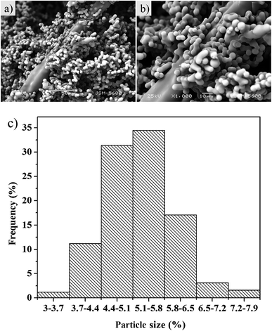 | ||
| Fig. 1 SEM images of the aerogel with 0.3% fibers at different magnifications (a and b) and the particle size distribution of aerogel (c). | ||
In the unmodified aerogel, an obvious –OH peak at 3500 cm−1 indicates that a significant fraction of the Si atoms exist as hydroxylated species on the surface in a gel network (Fig. 2). During the drying process at ambient pressure, these surface groups react to produce Si–O–Si bonds by condensation. The formation of Si–O–Si bonds collapses the pore network of the wet gel because of the high capillary pressures induced.38 The bands around 1096 cm−1 indicate Si–O–Si stretching vibrations, while the features around 798 cm−1 arise from Si–O vibrations. The adsorption bands at 3435 cm−1 can be assigned to hydroxyl groups. The peaks at around 2981–2900 cm−1 corresponded to C–H and CH3 bands, the main source of hydrophobicity. As can be seen the infrared spectra of the SiO2-modified aerogel, the H–OH peaks near 3425 and 1633 cm−1 are weakened to a certain degree, which can be explained by the aerogel modification. After being modified by TMCS, hydroxyl groups are substituted by –CH3 groups, resulting in more pronounced hydrophobic properties. Surface reactions occur homogeneously throughout the wet gel by diffusion along its open pore structure. That is, on the aerogel surface, hydroxyl (–OH) or alkoxy (–OR) groups were switched to stable SiR group, as verified from the thermogravimetric curve of the aerogel. The polyacrylonitrile fibers are added prior to the solution gel, where the fibers act merely as support frames for the gel. The fiber does not react chemically with the solution. Correspondingly, there is no chemical bond or chemical group change when aerogel is toughened by adding fiber. It can be seen that there is no large fluctuation in FTIR spectra with the exception of O–H or O–R and C–H peaks. Both the modified and unmodified aerogels are still typical amorphous materials, as shown in Fig. S9.†
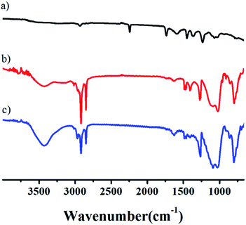 | ||
| Fig. 2 FTIR spectra of aerogels at the following compositions: (a) fibers, (b) aerogel with fiber content is 0.3%, (c) the unmodified aerogel. | ||
The contact angle of the unmodified aerogel was measured as >130°. In Fig. 3a, this value is 136° and can reach as high as 168° in Fig. 3b, which is considered superhydrophobic39 and suitable for the separation of oil–water mixtures. Fig. 3c shows that the aerogel weight reduction is mainly divided into three stages. In both cases, loss occurred between 20–290 °C corresponding to the evaporation and dissociation of unreacted water and organic solvents. In the second step, the major weight loss appears between 290–600 °C, as a result of severe –CH3 oxidation during the modification process. SiO2 residues were also present.40 The addition of fibers did not have much effect on the test results due to the low content of fibers in the aerogel. The aerogel with 0% fibers had a total mass loss of 30%, while that of the aerogel with 0.3% fibers was 22%.
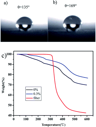 | ||
| Fig. 3 The contact angles of unmodified (a) and modified aerogels (b). TG curves of aerogels with different fiber contents and fiber (c). | ||
Quantitative analysis of the large-pore systems present in the aerogels (volume, size distribution) is scarcely possible from the nitrogen physisorption data alone, and therefore mercury intrusion porosimetry measurements were performed to determine the porosity within the aerogel monoliths.41 As measured by Hg intrusion porosimetry, the sizes of the macropores are mainly distributed in the range of 5–20 μm, with a maximum value of approximately 8 μm (Fig. 4a). The Brunauer–Emmett–Teller (BET) surface area of the aerogel is approximately 230 m2 g−1. The total intrusion volume of the aerogel is approximately 5.56 cm3 g−1 as shown in Fig. 4b.
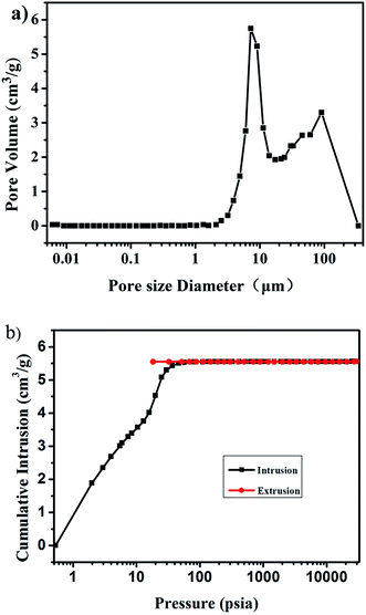 | ||
| Fig. 4 Pore size distribution of the aerogel with 0.3% fibers (a) and the cumulative intrusion as a function of pressure (b). | ||
Adsorption experiments
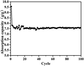
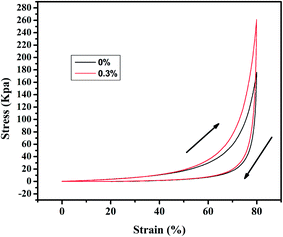
The aerogels' capacity to absorb diesel oil is indicated by the weight gain plotted in Fig. 5. To appraise the material as an oil/water separation medium, we tested its absorbing–squeezing circulation behavior using diesel oil as a model organic compound. The performance of the adsorbent was tested by a simple immersion-extrusion method. In the first cycle, the aerogel is clean when immersed. However, a small portion of the diesel fuel sticks to the aerogel because of its half-sticky during extrusion and the aerogel was then extruded completely without drying.45 These cause a decrease in the absorption capacity for the second cycle. In the following cycles, the absorption capacity will be a small range of fluctuations due to the operation of the extrusion error. But in the end it will stabilize. Over one hundred cycles, the aerogel showed stable behavior; the aerogel adsorbs 7.5× its dry weight in diesel oil, and no damage is observed.Stress–strain curves were obtained from compression testing of the aerogels as shown in Fig. 6 (the flexibility of the modified aerogels is shown in Fig. S8†). Complete recovery was observed after 40% compression, with an approximate modulus of 260 kPa for the aerogel with 0.3% fibers and approximately 180 kPa for the aerogel without fiber, demonstrating a linear elastic region up to approximately 80% strain.
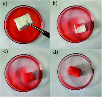
Diesel oil removal tests were also performed in this work to investigate the ability of the aerogel to separate and adsorb diesel oils (Fig. 7 and 8). Almost all of the diesel oil was successfully separated in a rapid manner within 1 min of exposure. For the separation of oil and water system of the adsorbent, oil–water selectivity is through the contact angle test to evaluate. Many researchers have demonstrated the contact angle of more than 150° indicates that the material has superhydrophobicity and good selectivity to oil and water through their researches and little adsorption of water is almost negligible.46,47 It can be seen that water is not adsorbed by aerogel in Fig. S12a† and aerogel floating on the water in Fig. S12b.† Due to the low mean density, the aerogel floated on the upper part of water and oil mixtures after the diesel oil was extracted completely, indicating that the system designed in this study is feasible for use in chemical spillages and elimination of oil leaks. Thus, these aerogels show great promise in separating dirt and oils from water due to their hydrophobicity, mechanical consistency and high porosity.
The aerogels were further tested by examining their adsorption for different organic pollutants.42 Different aerogels had different adsorption capacity for various organic pollutants when modified or unmodified, which all exceeded 6 g/g (Fig. 9). The addition of fiber did not affect the structure of the material, so the adsorption performances of aerogel with and without fibers have a little difference. Compared with other organic pollutants, the aerogel with 0.3% fibers showed the greatest adsorption capacity for N-methyl-2-pyrrolidone (NMP), with a value of 14.7 g/g. The adsorption capacity of aerogel did not change much, fluctuating about 0.2–0.6 g/g whether or not adding fiber. The organic molecules stockpile in the network structure of the aerogel and the weight ratio of absorbed solvent/dried gel depends on the density, viscosity, and surface tension of the absorbed liquids.
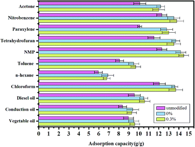 | ||
| Fig. 9 Adsorption capacities of the aerogels with different fiber contents and unmodified for various organic solvents and oils, as indicated by weight gain. | ||
Conclusions
We reported a novel silica aerogel material for oil adsorption from oil/water mixtures, using a preparation method that is relatively simple, economic, and environmentally friendly. This preliminary study indicates that polyacrylonitrile fibers are promising candidates as reinforcing additives to silica aerogels. The polyacrylonitrile fibers were successfully incorporated into the silica matrix with good dispersion, with an approximate modulus of 260 kPa for the aerogel with 0.3% fibers, indicating that polyacrylonitrile fibers reinforced the silica aerogels and improved their strength. At the same time, hydrophobic modification of the aerogel led to a water contact angle as high as 169°. The modified aerogels has obviously enhanced adsorption capacity and oil–water separation effects. Moreover, the superhydrophobic silica aerogel exhibits high oil-absorbing efficiency and could be directly applied to the water treatment industry.Acknowledgements
This research was financially supported by the Science and Technology Program Project of Jilin Province of China (No. 20130206069SF, 20150520012JH, 20160101322JC) and the Education Department of Jilin Province (No. 2016350).References
- M. O. Adebajo, R. L. Frost, J. T. Kloprogge, O. Carmody and S. Kokot, J. Porous Mater., 2003, 10, 159–170 CrossRef CAS.
- M. Toyoda and M. Inagaki, Carbon, 2000, 38, 199–210 CrossRef CAS.
- Q. Zhu, F. Tao and Q. M. Pan, ACS Appl. Mater. Interfaces, 2000, 2, 3141–3146 CrossRef PubMed.
- Q. Wei, R. Mather, A. Fotheringham and R. Yang, Mar. Pollut. Bull., 2003, 46, 780–783 CrossRef CAS PubMed.
- L. Feng, Z. Zhang, Z. Mai, Y. Ma, B. Liu, L. Jiang and D. A. Zhu, Angew. Chem., Int. Ed., 2004, 43, 2012–2014 CrossRef CAS PubMed.
- D. Ceylan, S. Dogu, B. Karacik, S. D. Yakan, O. S. Okay and O. Okay, Environ. Sci. Technol., 2009, 43, 3846–3852 CrossRef CAS PubMed.
- H. C. Bi, X. Xie, K. B. Yin, Y. L. Zhou, S. Wan, L. B. He, F. Xu, F. Banhart, L. T. Sun and R. S. Ruoff, Adv. Funct. Mater., 2012, 12, 4421–4425 CrossRef.
- Q. Zhu, Q. M. Pan and F. T. Liu, J. Phys. Chem. C, 2011, 115, 17464–17470 CAS.
- X. C. Dong, J. Chen, Y. W. Ma, J. Wang, M. B. Chan-Park, X. M. Liu, L. H. Wang, W. Huang and P. Chen, Chem. Commun., 2012, 48, 10660–10662 RSC.
- X. Y. Zhang, Z. Li, K. S. Liu and L. Jiang, Adv. Funct. Mater., 2013, 22, 2881–2886 CrossRef.
- A. Li, H. X. Sun, D. Z. Tan, W. J. Fan, S. H. Wen, X. J. Qing, G. X. Li, S. Y. Li and W. Q. Deng, Energy Environ. Sci., 2011, 4, 2062–2065 CAS.
- G. Hayase, K. Kanamori, M. Fukuchi, H. Kaji and K. Nakanishi, Angew. Chem., Int. Ed., 2013, 52, 1986–1989 CrossRef CAS PubMed.
- X. T. Zhu, Z. Z. Zhang, G. N. Ren, J. Yang, K. Wang, X. H. Xu, X. H. Men and X. Y. Zhou, J. Mater. Chem., 2012, 22, 20146–20148 RSC.
- T. Woignier, J. Reynes, A. Hafidialaoui, I. Beurroiesm and J. Phalippou, J. Non-Cryst. Solids, 1998, 241, 45–52 CrossRef CAS.
- Y. Li, W. P. Cai, B. Q. Cao, G. T. Duan, F. Q. Sun, C. C. Li and L. C. Jia, Nanotechnology, 2006, 17, 238–243 CrossRef CAS.
- D. A. Doshi, P. B. Shah, S. Singh, E. D. Branson, A. P. Malanoski, E. B. Watkins, J. Majewski, F. Swol and C. J. Brinker, Langmuir, 2005, 21, 7805–7811 CrossRef CAS PubMed.
- N. Leventis, C. Chidambareswarapattar, A. Bang and C. Sotiriou-Leventis, ACS Appl. Mater. Interfaces, 2014, 6, 6872–6882 CAS.
- G. T. Qin, Y. Yao, W. Wei and T. Zhang, Appl. Surf. Sci., 2013, 280, 806–811 CrossRef CAS.
- C. M. Wang, K. S. Chang, T. W. Chung and H. D. Wu, J. Chem. Eng. Data, 2004, 49, 527–531 CrossRef CAS.
- M. L. N. Perdigoto, R. C. Martins, N. Rocha, M. J. Quina, L. Go-Ferreira, R. Patrício and L. Durães, J. Colloid Interface Sci., 2012, 380, 134–140 CrossRef CAS PubMed.
- J. W. Tana, W. Sub, T. J. Doub and X. P. Fana, Sep. Sci. Technol., 2012, 47, 1149–1155 CrossRef.
- J. Cai, S. Liu, J. Feng, S. Kimura, M. Wada, S. Kuga and L. Zhang, Angew. Chem., Int. Ed., 2012, 51, 2076–2079 CrossRef CAS PubMed.
- M. A. B. Meador, Aerogels Handbook, Springer, 2011, part V, pp. 315–334 Search PubMed.
- V. A. Rao, S. D. Bhagat, H. Hirashima and G. Pajonk, J. Colloid Interface Sci., 2006, 300, 279–285 CrossRef PubMed.
- G. Hayase, K. Kanamori and K. Nakanishi, J. Mater. Chem., 2011, 21, 17077–17079 RSC.
- G. Hayase, K. Kanamori, K. Kazuki and T. Hanada, IOP Conf. Ser.: Mater. Sci. Eng., 2011, 18, 032013 CrossRef.
- H. Q. Guo, M. A. B. Meador, L. McCorkle, D. J. Quade, J. Guo, B. Hamilton, M. Cakmak and G. Sprowl, ACS Appl. Mater. Interfaces, 2011, 3, 546–552 CAS.
- X. Wang and S. C. Jana, ACS Appl. Mater. Interfaces, 2013, 5, 6423–6429 CAS.
- I. A. Sacui, R. C. Nieuwendaal, D. J. Burnett, S. J. Stranick, M. Jorfi, C. Weder, E. J. Foster, R. T. Olsson and J. W. Gilman, ACS Appl. Mater. Interfaces, 2014, 6, 6127–6138 CAS.
- Y. N. Duan, S. C. Jana, A. M. Reinsel, B. Lama and M. P. Espe, Langmuir, 2012, 28, 15362–15371 CrossRef CAS PubMed.
- D. B. Mahadika, A. V. Raoa, A. P. Raoa, P. B. Waghb, S. V. Ingaleb and S. C. Guptab, J. Colloid Interface Sci., 2011, 356, 298–302 CrossRef PubMed.
- B. N. Nguyen, E. Cudjoe, A. Douglas, D. Scheiman, L. McCorkle, M. A. B. Meador and S. J. Rowan, Macromolecules, 2016, 49, 1692–1703 CrossRef CAS.
- M. A. B. Meador, C. R. Alemán, K. Hanson, N. Ramirez, S. L. Vivod, N. Wilmoth and L. McCorkle, ACS Appl. Mater. Interfaces, 2015, 7, 1240–1249 CAS.
- H. Q. Guo, M. A. B. Meador, L. McCorkle, D. J. Quade, J. Guo, B. Hamilton and M. Cakmak, ACS Appl. Mater. Interfaces, 2012, 4, 5422–5429 CAS.
- Y. N. Duan, S. C. Jana, B. Lama and M. P. Espe, Langmuir, 2013, 29, 6156–6165 CrossRef CAS PubMed.
- A. V. Rao, D. P. Kulkami and T. Seth, Appl. Surf. Sci., 2003, 206, 262–270 CrossRef CAS.
- S. W. Hwang, T. Y. Kim and S. H. Hyun, J. Colloid Interface Sci., 2008, 322, 224–230 CrossRef CAS PubMed.
- M. Kanedal, O. Terasaki, D. Y. Zhao, J. M. Kim, G. Stucky, H. J. Shin and R. Ryoo, Nature, 2000, 408, 449–453 CrossRef PubMed.
- Z. T. Mazraeh-shahi, A. M. Shoushtari, A. R. Bahramian and M. Abdouss, Fibers Polym., 2014, 15, 2154–2159 CrossRef CAS.
- K. M. Aizawa, K. Nakanishi and T. Hanada, Adv. Mater., 2007, 19, 1589–1593 CrossRef.
- F. Irin, S. Das, F. O. Atore and M. J. Green, Langmuir, 2013, 36, 11449–11456 CrossRef PubMed.
- J. M. Al-Besharah, O. A. Salman and S. A. Akashah, Ind. Eng. Chem. Res., 1987, 12, 2445–2449 CrossRef.
- S. Y. Tao, Y. C. Wang and Y. L. An, J. Mater. Chem., 2011, 21, 11901–11907 RSC.
- X. L. Chen, L. L. Liu, K. Q. Liu, Q. Miao and Y. Fang, J. Mater. Chem. A, 2014, 2, 10081–10089 CAS.
- S. Venkatanarasimhan and D. Raghavachari, J. Mater. Chem. A, 2013, 1, 868–876 CAS.
- M. Patowary, K. Pathak and R. Ananthakrishnan, RSC Adv., 2015, 5, 79852–79859 RSC.
- Z. X. Xue, Y. Z. Cao, N. Liu, L. Feng and L. Jiang, J. Mater. Chem. A, 2014, 2, 2445–2460 CAS.
Footnote |
| † Electronic supplementary information (ESI) available: SEM images, experimental parameters of silica aerogels. See DOI: 10.1039/c6ra26831e |
| This journal is © The Royal Society of Chemistry 2017 |

