
 Open Access Article
 This Open Access Article is licensed under a
 Creative Commons Attribution 3.0 Unported Licence
Revealing the three-dimensional filler structure in a rubber matrix based on fluorescein modified layered double hydroxides†
Weiyang Lv,
Miao Du *,
Jianliang Xiao,
Yihu Song and
Qiang Zheng
*,
Jianliang Xiao,
Yihu Song and
Qiang Zheng
MOE Key Laboratory of Macromolecular Synthesis and Functionalization, Department of Polymer Science and Engineering, Zhejiang University, Hangzhou, 310027, China. E-mail: dumiao@zju.edu.cn; Fax: +86-571-87953075; Tel: +86-571-87953075
First published on 16th January 2017
Abstract
To gain insight into nonlinear viscoelastic behavior, e.g. the Payne effect, and in situ visualize the filler structure in a rubber matrix under strain, a methodology was developed to detect and track structural evolution based on fluorescent labeling. As a model system, layered double hydroxides (LDHs) with different lateral sizes (nanosheets and microsheets) were labeled with fluorescein (FLU) and then uniformly introduced into the rubber matrix through solution blending. The strain-induced deformation and destruction of the three-dimensional LDH filler structure were directly observed for the first time through laser scanning confocal microscopy (LSCM). The contributions of the breakdown of the filler network, strain softening of the glassy layer and macromolecular disentanglement to the Payne effect were qualitatively determined and analyzed in detail based on the structural information probed via LSCM together with transmission electron microscopy, rheometry and modulated differential scanning calorimetry. The primary mechanism for the Payne effect in this system was then proposed and the macromolecular disentanglement in the rubber matrix played a key role. Furthermore, the enhanced Payne effect with increasing LDH content was ascribed to the strain amplification effect induced by the filler network for the LDH nanosheet filled system and the chain sliding on orientated LDHs for microsheet filled compounds, respectively.
Introduction
Filled rubbers with excellent mechanical properties and broad applications are an important industrial material that has received considerable attention for many decades.1,2 Generally, carbon black and silica are the two most widely used reinforcing fillers due to their finer capacity to form hierarchical structures.3,4 Though the importance of the filler structure in a rubber matrix has been well recognized, the mechanisms for reinforcement and nonlinear viscoelasticity still remain under debate. The Payne effect, commonly known as strain softening, is one of the specific nonlinear viscoelastic behaviors that have been investigated for many years due to both theoretical and practical importance.5–7 A number of theories have been proposed to account for the Payne effect and can be divided into three major scenarios. In one scenario, the nonlinear viscoelastic behavior with respect to strain amplitude is attributed to the deagglomeration and breakdown of the filler network.8,9 Different from this particle-only scenario, some researchers emphasize that the rubber-particle interfacial interactions are responsible for the Payne effect,10,11 which is mainly described as the softening of glassy layer during straining. The final scenario proposed by Sun is that the Payne effect is ascribed to the macromolecular disentanglement while the fillers can facilitate this process via strain amplification effect.12–15 Since all the above theories relate to the filler in compounds, it is of particular importance to visualize the filler structure in rubber matrix, especially the structural evolution under straining. Unfortunately, it still is a fundamental challenge to observe the filler structure under different strains due to the poor spatial resolution of optical microscope and the limited operating environment of electron microscope. Synchrotron radiation X-ray nano-computed tomography has been recently reported to provide a new way to characterize the filler structure, while the extremely shallow focal depth of X-ray imaging system restricts its wider applications.16By virtue of the simplicity and inherent low detection limits, fluorescent labeling has been employed to characterize the dispersion of carbon nanotubes and layered silicates in polymer composites.17,18 Among the fluorescence indicators, fluorescein (FLU) has been extensively studied due to its high quantum yield and stability.19 To achieve the high performance of chromophore-inorganic composite materials, layered double hydroxide (LDH), a large family of lamellar materials whose structure can be generally expressed as [M1−x2+Mx3+(OH)2](An−)x/n·mH2O (where M2+ and M3+ are divalent and trivalent metal ions in positively charged layers, and An− is the interlayer anions),20 was selected as the inorganic matrix where the chromophore aggregation could be effectively inhibited via host–guest interactions (e.g., electrostatic interaction, hydrogen bonding).21 Moreover, LDH as a potential material in elastomer technology has attracted intense research interest due to their application in reinforcement, vulcanization, flame retardant and so on.2,22–24 Even though, up to now, the reports on rubber–LDH composites are still quite limited and their dynamic properties have seldom been reported, not to say the systematic investigation combined the rheological behavior with direct evidence of filler structural evolution under loading.
In this work, aiming to reveal the three-dimensional (3D) filler structure evolution in rubber matrix, fluorescein modified LDHs with different crystal sizes (nanosheets and microsheets) were introduced into the rubber matrix through solution blending, and laser scanning confocal microscopy (LSCM) was then employed to monitor the filler structure under different strains owing to its outstanding capability in analyzing emission intensity as a function of the z-position.25 After stretching, the filler (LDHs) structural evolution (such as the filler aggregates, filler network and so on) would be observed and analyzed. Combined the structural information probed via LSCM with the results including transmission electron microscope, rheometer and modulated differential scanning calorimetry, the primary mechanism for Payne effect in this system was discussed in detail.
Experimental section
Materials
Magnesium nitrate hexahydrate, aluminum nitrate nonahydrate, sodium hydroxide, urea and toluene were purchased from Sinopharm Chemical Reagent Co., Ltd., China. Fluorescein sodium salt (FLU) was supplied by the Aladdin reagent (Shanghai, China). Styrene butadiene rubber (SBR 1502 with a styrene content of 27%, Fig. S1†) was obtained from Qilu Petrochemical Co., Sinopec. Distilled water was used in the experiments. All the reagents were used as the received without further purification.Synthesis of FLU modified LDHs
The LDH precursors with different lateral sizes (nanosheets and microsheets) were prepared via hydrothermal treatment and urea releasing method, respectively.26,27 Subsequently, the obtained LDHs were ultrasonically treated in distilled water for 1 h to obtain a stable colloidal aqueous dispersion. Next, a desired amount of FLU was dissolved in the dispersion, followed by substantial stirring for two days. The resulting precipitates were collected by filtration and washed with deionized water for several times until the filtrate was colorless. The final products (FLU modified LDH, i.e. F-LDH particles) were obtained by the freeze-drying method.Fabrication of the SBR/F-LDH compounds
The preparation procedure was shown in Scheme 1. A certain amount of F-LDH particles (ϕF, respect to rubber content) were ultrasonically treated in 300 mL toluene for 1 h, and then the dispersion was refluxed at 80 °C for 2 h. 25 g SBR were introduced into the system with vigorous stirring until a transparent dispersion was obtained. Next, the mixture was transferred to a rotary evaporator for removing the solvent and followed by drying in a vacuum oven at 60 °C overnight. The SBR/F-LDH compounds underwent further mixing by using a laboratory two-roll open mill (XK-160, Zhanjiang Rubber & Plastic Machinery Co., Ltd., China) and then were compressed into sheets on a press vulcanizer (XL-25, Huzhou Xinli Rubber Machinery Co., Ltd., China) at 140 °C under 14.5 MPa for 15 min. Samples of 1.5 and 0.5 mm in thickness were prepared for rheological test and LSCM observation, respectively.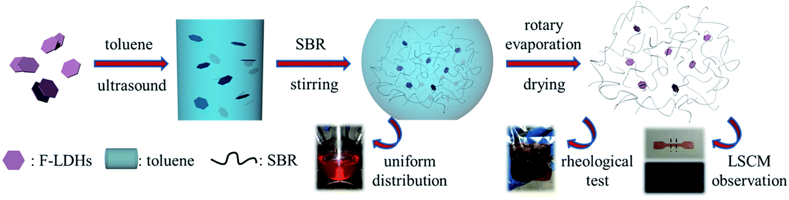 | ||
| Scheme 1 Illustration showing the fabrication of SBR/F-LDH compounds via a solution blending method. | ||
Characterization
The weight contents of structural units in SBR were calculated using 1H nuclear magnetic resonance (1H NMR) spectroscopy acquired on a Bruker Avance III 500 MHz spectrometer. The morphologies of the LDHs were observed by transmission electron microscope (TEM, JEOL, JEM-1200EX, Japan). The samples were ultrasonically dispersed in ethanol for 1 h before being transferred to the microscope. Fluorescence images were taken on an optical microscope (Eclipse TE2000, Nikon, Japan) equipped with a highly sensitive CCD camera (ORCA-ER, Hamamatsu Photonics, Japan). The dispersion of F-LDH particles in compounds was investigated using TEM (JEOL, JEM-1230EX, Japan). The ultra-thin sections of the samples were prepared by ultramicrotomy (Leica, CM1900) at −120 °C. X-ray diffraction (XRD) patterns were recorded on a Rigaku D/max 2550 diffractometer (Shimadzu Corporation, Japan) under the following conditions: 40 kV, 300 mA, Cu Kα radiation (λ = 0.1542 nm). A strain-controlled rheometer (ARES-G2, TA Instruments, USA) was used to measure the linear and nonlinear dynamic rheological responses of the compounds at 100 °C. Modulated differential scanning calorimetry (MDSC, Q100, TA Instruments, USA) was used to measure the heat capacity and glass transition temperature (Tg) of compounds. Measurements were performed by using an underlying heating rate of 1 °C min−1 with an amplitude of 1 °C and a period of 120 s. A laser scanning confocal microscopy (LSCM, LSM780 META Carl Zeiss, Germany) was used to detect the structural evolution of F-LDHs in compounds during straining. The filter setup consisted of an excitation source (488 nm laser) and emission band-pass filter (493–553 nm). The images were taken at 40–60× magnification using immersion lenses, with a pinhole of 107 μm. After stretching, the samples were fixed on the slide glass via adhesive tape.Results and discussion
Morphologies of LDHs and F-LDHs
The LDH precursors with different crystal sizes (nanosheets and microsheets, denoted as NLDHs and MLDHs) are displayed in Fig. 1. NLDHs with a mean lateral size of 50 nm were uniformly distributed in the field of vision. While for MLDHs, highly crystallized and well-defined hexagonal platelets were observed with a lateral size as large as 4 μm. The TEM images indicated that these two types of LDH particles were strictly synthesized and should be suitable for the following fluorescent modification.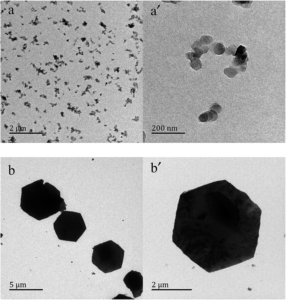 | ||
| Fig. 1 TEM micrographs of the NLDHs (a, a′) and MLDHs (b, b′) with different magnifications. | ||
The proper labeling of LDH particles with FLU was verified by fluorescence microscope. As shown in Fig. 2, the F-LDH particles exhibited strong brightness of green light in fluorescence mode where the background was still black, demonstrating the successful attachment of the FLU to the LDH particles. As for FLU modified NLDHs (F-NLDHs), only aggregates could be detected due to the poor resolution of fluorescence microscope, while clear outline of some LDH platelets was observed for FLU modified MLDHs (F-MLDHs). The XRD patterns of NLDHs and MLDHs with or without FLU modification are presented in Fig. 2c. All the patterns exhibited characteristic reflections corresponding to the (003), (006) and (012) planes of CO32− intercalated LDHs.27 The diffraction peaks were sharp and narrow for MLDHs, revealing the highly crystalline nature of LDHs obtained via the urea releasing method.28 Note that the changes in (003) reflection with the average interlayer distance of 0.75 nm were not detected for both NLDHs and MLDHs after FLU modification. This indicated that the fluorescein only attached to the surface of LDHs through the electrostatic interaction instead of intercalating into the LDH layers. Nevertheless, the immobilized effect caused by the electrostatic interaction was strong enough to prevent the fluorescein releasing from the LDH surface to the matrix, which could also be testified by the fluorescence microscope where the rubber matrix was black in the vision and would not affect the observation of F-LDHs in compounds (Fig. S2†).
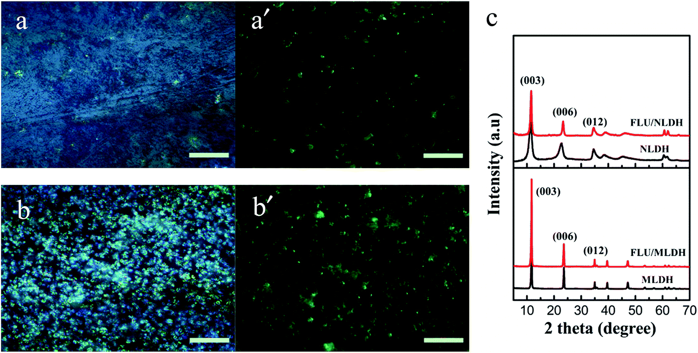 | ||
| Fig. 2 (a, b) Optical micrographs of the F-NLDHs and F-MLDHs and (a′, b′) their corresponding fluorescent micrographs. (c) XRD patterns of the LDH products before and after fluorescein modification. The scale bars are 20 μm in the micrographs. | ||
Dispersion of F-LDH particles in rubber matrix
To achieve ideal performance and reliable LSCM observation, homogenous and stable dispersion of the FLU modified LDH particles into the rubber matrix is required. Fig. 3 illustrates the TEM images for SBR compounds containing F-LDH particles with various ϕF. In SBR/F-NLDH compounds, F-NLDHs were well dispersed in SBR matrix with random orientation. With the increase in ϕF (such as at ϕF = 15 wt%), a particle network structure was obviously formed in rubber matrix and thus would restrict the random orientation of F-NLDHs during preparing samples with compression, and to some extent cause a significant proportion of F-NLDHs orientating along the direction being perpendicular to the cross section. As for SBR/F-MLDH compounds, the orientated F-MLDHs were always observed in the matrix with different ϕF, which might be ascribed to the large lateral size of the crystals. However, evident F-MLDH network could not be found even at ϕF = 20 wt%.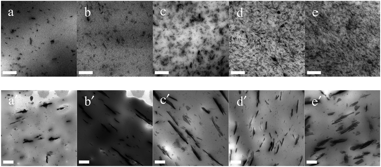 | ||
| Fig. 3 TEM micrographs showing F-NLDHs and F-MLDHs dispersion from ultrathin section of SBR compounds with various ϕF: (a, a′) 3 wt%, (b, b′) 6 wt%, (c, c′) 10 wt%, (d, d′) 15 wt%, (e, e′) 20 wt%. The scale bars for SBR/F-NLDH and SBR/F-MLDH compounds are 0.5 and 2 μm, respectively. | ||
Rheological behavior of SBR/F-LDH compounds
Plots of storage modulus (G′) versus angular frequency (ω) for compounds containing F-NLDHs and F-MLDHs of various ϕF are shown in Fig. 4. Addition of the both F-LDH particles into SBR increased the G′ throughout the tested frequency range. This tendency was more pronounced for F-NLDH filled system due to its large specific surface area.29 Moreover, a jump in G′ occurred from 10 wt% to 15 wt% for SBR/F-NLDH compounds, which was the evidence of percolation, i.e. a particle network structure was formed in the compounds.30 After that, with further increasing ϕF, G′ in low-ω region only showed a little increase compared with that of 15 wt% system. This unusual rheological behavior was different from the traditional carbon black and silica filled rubber where G′ increased markedly with ϕF after percolation.12,31 The secondary structure difference between F-NLDHs and carbon black (or silica) might account for this unusual phenomenon. F-NLDHs with layered structure tended to form “house of cards” like aggregates in rubber matrix,32,33 and these loosely attached structures gave rise to a weak filler network that caused a limited increase in G′ in low-ω region. In addition, the LDH orientation would be more evident at ϕF = 20 wt%, which could also decrease the dynamic modulus of the compounds.34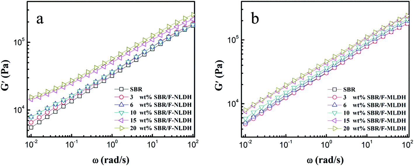 | ||
| Fig. 4 Oscillatory shear rheology curves of G′ as a function of ω at 100 °C for compounds filled with (a) F-NLDHs and (b) F-MLDHs, respectively. | ||
Generally, the percolation threshold for microsized particles was higher than that of nanosized fillers.35 That is to say, the percolation threshold for F-MLDH filler systems should be larger than 15 wt%. As expected, G′ increased with ϕF (3–20 wt%) in low-ω region without an obvious jump throughout the tested samples due to its large size. The rheological behaviors were consistent with the above TEM observation.
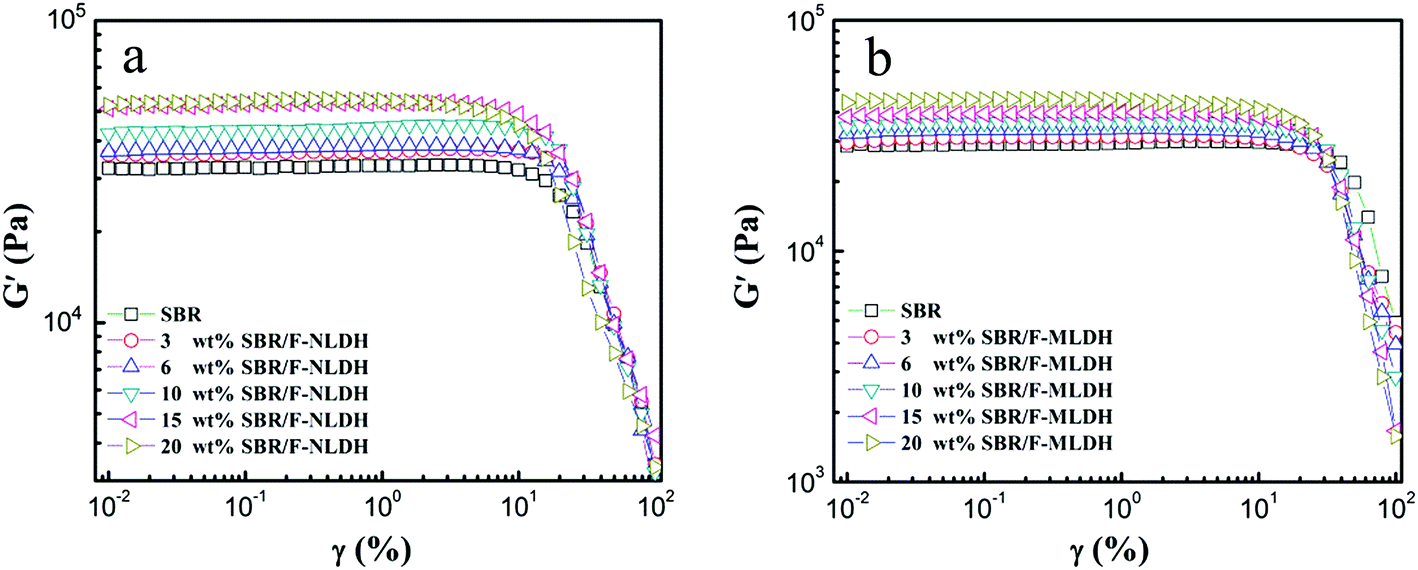
Strain sweep measurements have been carried out to study the nonlinear rheological behavior of compounds containing F-NLDHs and F-MLDHs, respectively. Here both the two types of compounds showed strong strain (γ) dependence of G′ that was similar to other conventional filled systems (Fig. 5), which was known as the Payne effect. G′ remained constant until γ reached a critical strain (γc), and hereafter decreased rapidly at high γ. The γc for F-NLDH and F-MLDH filled systems was shown in Fig. S3.† For F-NLDH filled compounds, the curves at γ > γc were almost overlapped at ϕF ≤ 15 wt%. As aforementioned, filler network was formed at ϕF = 15 wt% and could be severely destructed at γ > γc, which should give rise to the distinct rheological response different from the pure SBR at large strain. However, the similar nonlinear behaviors of the compounds at ϕF ≤ 15 wt% demonstrated that the Payne effect might not assign to the breakdown of filler network structure but root in the macromolecular disentanglement in rubber matrix.12 With further increasing ϕF to 20 wt%, the value of γc decreased and the Payne effect was enhanced. At ϕF ≤ 15 wt%, the strain amplification arising from the fillers was very weak, while this effect would show a notable increase after percolation.14 Only in this case, the nanoparticle network structure could contribute to the macromolecular disentanglement via strain amplification effect (the third scenario account for the Payne effect).
 | ||
| Fig. 5 Oscillatory shear rheology curves of G′ as a function of γ at 100 °C for compounds filled with (a) F-NLDHs and (b) F-MLDHs, respectively. | ||
The nonlinear viscoelastic behavior was somehow different for SBR/F-MLDH compounds where G′ at γ > γc could not overlap even at low ϕF but decrease sharper and sharper with increasing ϕF. As discussed before, particle network structure was not formed at ϕF ≤ 20 wt% for SBR/F-MLDH compounds. On this occasion, strain amplification induced by filler network could not explicate the enhanced Payne effect at low ϕF. The underlying factor that facilitated the macromolecular disentanglement in SBR/F-MLDH compounds should be further explored and would be discussed in detail later.
Interaction between SBR and F-LDH particles
For filled rubber compounds, the presence of glassy layer around the filler surface was generally detected when the interaction between the matrix and fillers was sufficiently strong, and the nonlinear Payne effect could be observed in the compounds as a result of dynamical yield of glassy layer.11 MDSC was employed to investigate the interaction between polymer chains and fillers, especially for quantifying the immobilized matrix fraction (glassy layer) in the filled compounds.36,37 Fig. 6a displays the reversing heat capacity step (ΔCp) of the rubber fraction in SBR/F-NLDH compounds with various ϕF. Since the ΔCp of F-NLDHs was sufficiently small with respect to SBR during glass transition, ΔCp of the rubber fraction could be calculated by ΔCp,rubber = ΔCp,sample/(1 − XLDH), where XLDH is the mass fraction of LDH in the samples. The identical values of ΔCp,rubber indicated that the amount of glassy segment that totally not contribute to the glass transition was none or too small to be detected, as clearly illustrated in Fig. 6b. Therefore, it was rational to conclude that the contribution of strain softening of glassy layer to the Payne effect was marginally small in this system. In other words, the rubber–particle interfacial interaction was not responsible for the nonlinear behavior and the second scenario for Payne effect could be readily excluded. In addition, the glass transition temperature (Tg) was determined at the inflection point of the curves in Fig. 6a. For all the compounds, Tg (−55.2 °C) was almost uninfluenced by ϕF (Fig. S4†) owing to the weak interaction between the matrix and the filler arising from the organic–inorganic incompatibility.2 The MDSC results of F-MLDH filled system were also consistent with that of SBR/F-NLDH compounds as discussed above (Fig. S5 and S6†).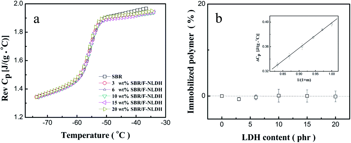 | ||
| Fig. 6 (a) Reversing heat capacity of the rubber fraction in the F-NLDH filled compounds with various ϕF. (b) Immobilized layer amount as a function of ϕF. The insert shows the ΔCp of compounds as a function of rubber fraction. | ||
LSCM observation of SBR/F-LDH compounds
For LSCM imaging experiments, a 3D visualization of SBR/F-LDH compounds was generated through optical sectioning.38 Sample slices of the 3D images were 0.5 μm for SBR/F-NLDH and 1.0 μm for SBR/F-MLDH compounds, respectively. In order to quantitatively describe the LDH filler structure during stretching, crucial parameters such as the cluster size and inter-aggregate distance were calculated by ImageJ software. The values of these parameters are usually not constant and depend on the observation image size.38 Since the analysis domains of LSCM images are about hundred micrometers in this work, these data can provide a bulk-scale characterization of the compounds. Before analyzing these parameters, the threshold chosen was important to determine the components in the samples. The threshold was modified and determined for several times until the calculated values were close to the actual volume values.39 Fig. 7 shows the representative image of SBR/F-NLDH compounds with 3 wt% F-NLDHs. Single particle dispersion in matrix was beyond the spatial resolution limitation of the LSCM (350 nm per pixel);40 instead the F-NLDH aggregates with sizes from 0.5 μm to 8.0 μm were observed in the two-dimensional (2D) imaging. The 3D visualization showed that the F-NLDH aggregates were uniformly dispersed in the rubber matrix. After stretched to the strain of 100%, it seemed that the filler dispersed more homogeneously. Basing on the ImageJ software statistical data, the frequency of F-NLDH aggregates below the size of 1.0 μm increased from 70.81% to 75.52%. Meanwhile, the content of aggregates larger than 5 μm was about 0.73% at strain of 0%, and then decreased to 0.23% at strain of 100%. These synchronous changing trends between small and large aggregates revealed that breakdown of filler aggregates occurred under stretching, which was consistent with the previous prediction.41 The dispersion of LDH aggregates in 3D space confirmed intuitively the above results where the aggregate density increased due to the splitting of large aggregates into small ones. Since the breakdown of filler aggregates at large strain was not reflected on the rheological response, it was evident that deagglomeration played a minor role in nonlinear viscoelasticity in this system (Fig. 5a). Therefore, the first scenario for Payne effect, i.e. the nonlinear viscoelastic behavior with respect to strain amplitude is attributed to the deagglomeration and breakdown of filler network, could also be excluded. The LSCM imaging of 10 wt% and 20 wt% SBR/F-NLDH compounds are displayed in Fig. S7 and S8.† With increasing ϕF, the average size of aggregates increased at first (1.023 μm at ϕF = 3 wt% and 1.161 μm at ϕF = 10 wt%) and then kept nearly consistent (1.106 μm at ϕF = 20 wt%). Additionally, the packing structure of F-NLDH aggregates was closer at high ϕF as presented in 3D imaging, especially for ϕF = 20 wt% system where a compact rectangular structure was observed, which provided further powerful evidence of the formation of filler network.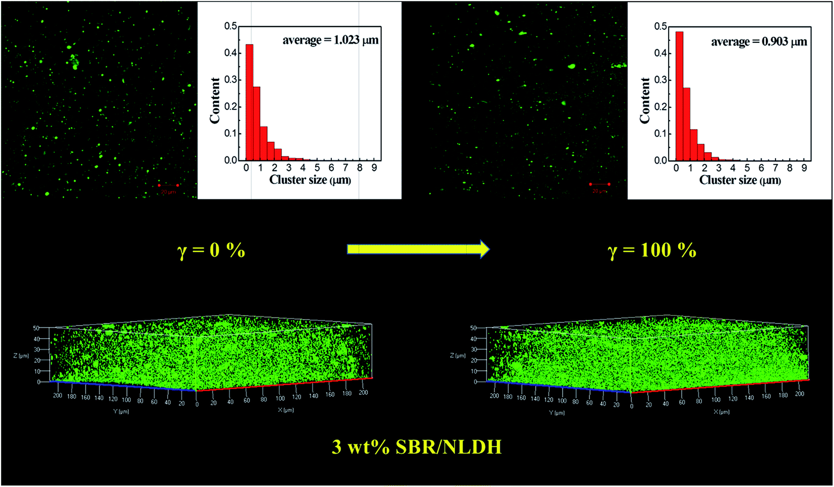 | ||
| Fig. 7 LSCM observation of the 3 wt% SBR/F-NLDH compounds before and after stretched to the strain of 100%. The histograms are the size distribution of F-NLDH aggregates. | ||
For F-MLDH filled system shown in Fig. 8, the outline of particles was clearly observed where the rubber matrix was black. After stretched to the strain of 100%, the average size of aggregates decreased while the inter-aggregate distance increased. In light of the lower aggregation degree for F-MLDHs than that of F-NLDHs, the cluster density showed a limited increase after stretching. In this case, due to the increased inter-aggregate distance, the sparse packing structure of F-MLDHs was more distinct in 3D visualization after stretching. With increasing ϕF, the variation of aggregate size for F-MLDHs before and after stretching was similar to that of F-NLDHs (Fig. S9 and S10†), i.e. the average size of F-MLDHs also increased at first and then kept consistent, and the value would decrease under straining. Specifically, the filler aggregates were closely packed in 20 wt% SBR/F-MLDH compound such that fuzzy images were obtained at strain of 0%. After stretching, the LDH particles could be discerned and showed a similar structure with that of compounds at low ϕF. This phenomenon categorically confirmed the enlarged inter-aggregate distance during straining.
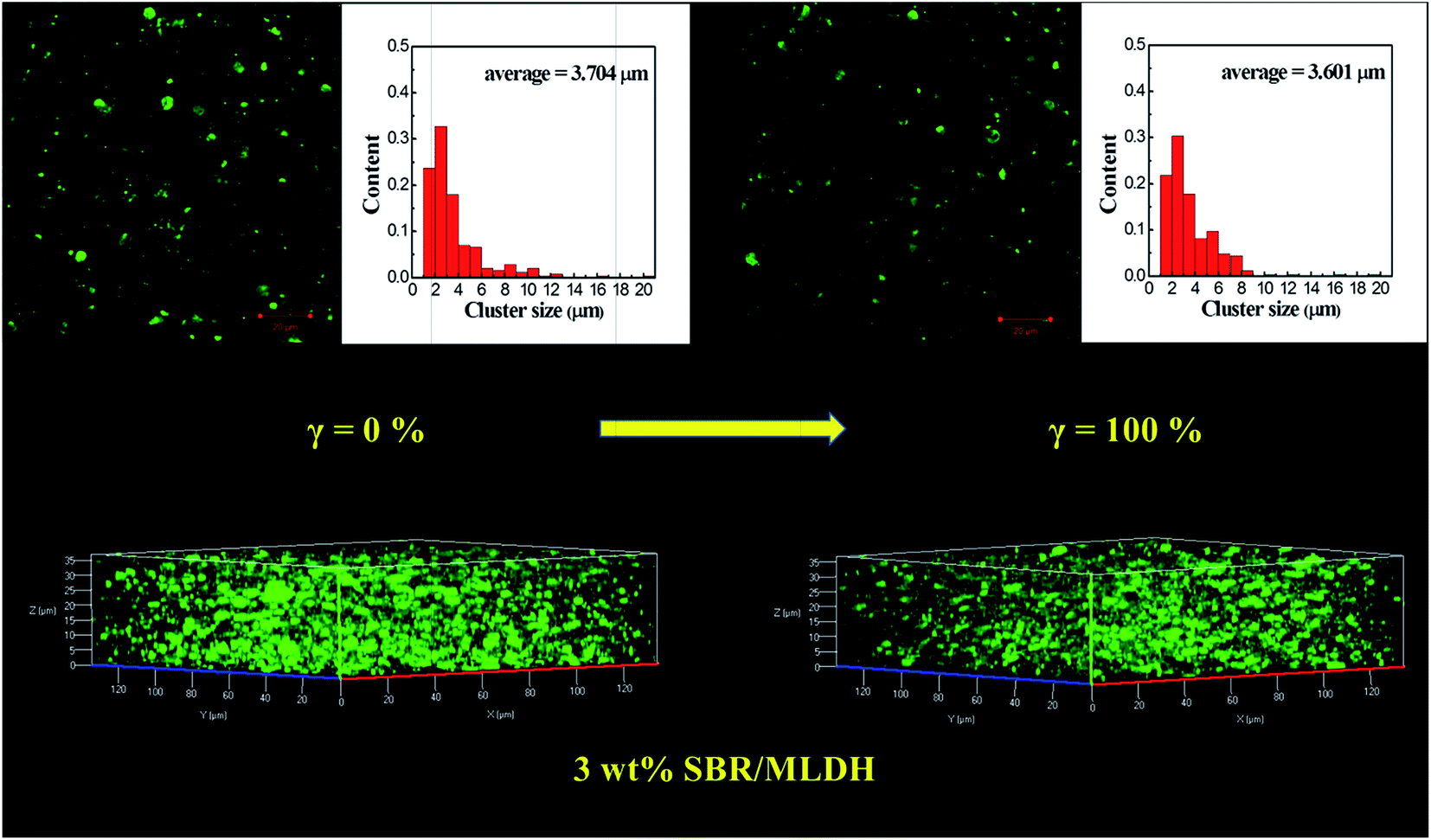 | ||
| Fig. 8 LSCM observation of the 3 wt% SBR/F-MLDH compounds before and after stretched to the strain of 100%. The histograms are the size distribution of F-MLDH aggregates. | ||
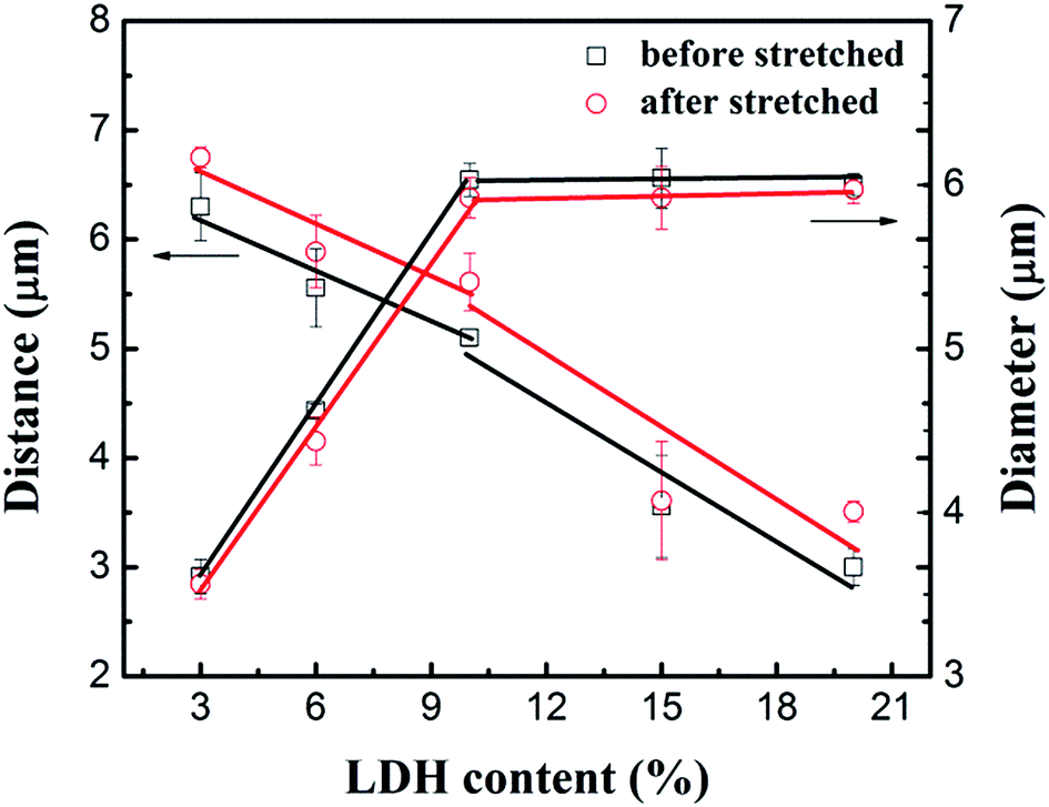
Fig. 9 plots the average inter-aggregate distance and aggregate size as a function of ϕF before and after stretching for SBR/F-MLDH compounds. The aggregate size increased remarkably at ϕF < 10 wt% along with the decrease of inter-aggregate distance. With further increase in ϕF, the inter-aggregate distance showed a sharper decrease while the aggregate size kept almost constant. Considering the variation of aggregate size and inter-aggregate distance, a conclusion was drawn that the F-MLDH aggregates would reach its maximum size with increasing ϕF to a critical value (in this system ϕF ≈ 10 wt%). After that, further increasing ϕF would only cause the decrease of inter-aggregate distance without the notable change of aggregate size, and when the distance decreased to a threshold value (the value was not reached even at ϕF = 20 wt% for F-MLDH filled system), the filler network was formed. After stretching, the F-MLDH aggregates did not actually suffer the same strain with the macroscopic strain.42,43 For the three SBR/F-MLDH compounds, the inter-aggregate distance only increased 10% or so while the macroscopic strain for the samples was 100%. This indicated that sliding between F-MLDH particles and rubber chains did occur. Since the F-MLDHs with large lateral size were always orientated to the tensile direction in rubber matrix, the strong slip of rubber chains on F-MLDH surface could be analogous to the condition where chain desorption and macromolecular disentanglement led to the wall slip of molten polymer in a flowing process (shown in Fig. S11†).44–46 The rubber chains in the matrix were stretched and these in turn applied force to the chains at interface (the stress transfer was usually more efficient in the composites with orientated fillers) through the entanglement during straining. Due to the weak interaction between F-MLDHs and rubber chains, the force required to induce the chain desorption and macromolecular disentanglement on the orientated filler surface was small, and as a result the entanglement density was reduced during straining, followed by the strong slip of rubber chains. That is, the orientated F-MLDHs could facilitate the macromolecular disentanglement and lead to the enhanced Payne effect subsequently. As for F-NLDH filled systems, slippages of rubber chains along the randomly orientated particles with a mean lateral size of 50 nm was inapparent, and thus the enhanced Payne effect at high ϕF was ascribed to the strain amplification effect caused by the filler network.
 | ||
| Fig. 9 Average inter-aggregate distance and aggregate diameter as a function of ϕF for F-MLDH filled compounds before and after stretched to strain of 100%. | ||
Conclusions
In summary, we have developed an effective methodology to present the 3D filler structure in a rubber matrix. With increasing LDH contents, the variation trend for average diameter of aggregates was increased at first and then kept constant, and the reverse was true for inter-particle distance. Large LDH aggregates splitting into small ones were observed for both nano- and microsheet filled systems during stretching while the contribution was not found on rheological responses, implying that the Payne effect from deagglomeration and network breakdown was minor. Moreover, the glassy layer on LDH surface was not detected via MDSC, demonstrating that the strain softening of glassy layer could also not account for the nonlinear viscoelasticity. The similar rheological behavior between unfilled and filled SBR indicated that the essential mechanism for the Payne effect lay in the nature of macromolecular disentanglement in the matrix, and the enhanced Payne effect with increasing LDH contents was ascribed to the strain amplification effect induced by the filler network for nanosheet filled system and the chain sliding on orientated LDHs for microsheet filled compounds, respectively. We believe that these findings present in this work provide a clear visualization of filler structure under straining and will be helpful in exploring the structure–property of compounds.Acknowledgements
This work was supported by the National Natural Science Foundation of China (Key Program, Grant 51333004).Notes and references
- J. L. Leblanc, Prog. Polym. Sci., 2002, 27, 627 CrossRef CAS.
- D. Basu, A. Das, K. W. Stockelhuber, U. Wagenknecht and G. Heinrich, Prog. Polym. Sci., 2014, 39, 594 CrossRef CAS.
- T. Koga, T. Hashimoto, M. Takenaka, K. Aizawa, N. Amino, M. Nakamura, D. Yamaguchi and S. Koizumi, Macromolecules, 2008, 41, 453 CrossRef CAS.
- D. Zhao, S. F. Ge, E. Senses, P. Akcora, J. Jestin and S. K. Kumar, Macromolecules, 2015, 48, 5433 CrossRef CAS.
- J. X. Shen, J. Liu, Y. Y. Gao, X. L. Li and L. Q. Zhang, Soft Matter, 2014, 10, 5099 RSC.
- R. Kreiselmaier, Kautsch. Gummi Kunstst., 2014, 67, 16 CAS.
- J. Yang and C. R. Han, J. Phys. Chem. C, 2013, 117, 20236 CAS.
- Y. Rharbi, B. Cabane, A. Vacher, M. Joanicot and F. Boue, Europhys. Lett., 1999, 46, 472 CrossRef CAS.
- A. D. Drozdov and A. Dorfmann, Polym. Eng. Sci., 2002, 42, 591 CAS.
- A. Mujtaba, M. Keller, S. Ilisch, H. J. Radusch, T. Thurn-Albrecht, K. Saalwachter and M. Beiner, Macromolecules, 2012, 45, 6504 CrossRef CAS.
- S. Merabia, P. Sotta and D. R. Long, Macromolecules, 2008, 41, 8252 CrossRef CAS.
- J. Sun, Y. H. Song, Q. Zheng, H. Tan, J. Yu and H. Li, J. Polym. Sci., Part B: Polym. Phys., 2007, 45, 2594 CrossRef CAS.
- Y. H. Song and Q. A. Zheng, Polymer, 2010, 51, 3262 CrossRef CAS.
- Y. H. Song and Q. A. Zheng, Polymer, 2011, 52, 593 CrossRef CAS.
- Y. H. Song and Q. Zheng, Polymer, 2011, 52, 6173 CrossRef CAS.
- L. Chen, W. M. Zhou, J. Lu, J. Li, W. H. Zhang, N. D. Huang, L. H. Wu and L. B. Li, Macromolecules, 2015, 48, 7923 CrossRef CAS.
- P. H. Maupin, J. W. Gilman, R. H. Harris, S. Bellayer, A. J. Bur, S. C. Roth, M. Murariu, A. B. Morgan and J. D. Harris, Macromol. Rapid Commun., 2004, 25, 788 CrossRef CAS.
- R. A. Graff, J. P. Swanson, P. W. Barone, S. Baik, D. A. Heller and M. S. Strano, Adv. Mater., 2005, 17, 980 CrossRef CAS.
- A. W. Musumeci, G. M. Mortimer, M. K. Butler, Z. P. Xu, R. F. Minchin and D. J. Martin, Appl. Clay Sci., 2010, 48, 271 CrossRef CAS.
- P. J. Sideris, U. G. Nielsen, Z. H. Gan and C. P. Grey, Science, 2008, 321, 113 CrossRef CAS PubMed.
- W. Y. Shi, S. He, M. Wei, D. G. Evans and X. Duan, Adv. Funct. Mater., 2010, 20, 3856 CrossRef CAS.
- A. Das, D. Y. Wang, A. Leuteritz, K. Subramaniam, H. C. Greenwell, U. Wagenknecht and G. Heinrich, J. Mater. Chem., 2011, 21, 7194 RSC.
- A. Das, J. Jacob, G. B. Kutlu, A. Leuteritz, D. Y. Wang, S. Rooj, R. Jurk, R. Rajeshbabu, K. W. Stockelhuber, V. Galiatsatos and G. Heinrich, Macromol. Rapid Commun., 2012, 33, 337 CrossRef CAS PubMed.
- A. Laskowska, M. Zaborski, G. Boiteux, O. Gain, A. Marzec and W. Maniukiewicz, Eur. Polym. J., 2014, 60, 172 CrossRef CAS.
- C. A. Diaz, Y. N. Xia, M. Rubino, R. Auras, K. Jayaraman and J. Hotchkiss, Nanoscale, 2013, 5, 164 RSC.
- S. Huang, G. N. Zhu, C. Zhang, W. W. Tjiu, Y. Y. Xia and T. X. Liu, ACS Appl. Mater. Interfaces, 2012, 4, 2242 CAS.
- Z. P. Liu, R. Z. Ma, M. Osada, N. Iyi, Y. Ebina, K. Takada and T. Sasaki, J. Am. Chem. Soc., 2006, 128, 4872 CrossRef CAS PubMed.
- W. Y. Lv, M. Du, W. J. Ye and Q. Zheng, J. Mater. Chem. A, 2015, 3, 23395 CAS.
- Q. Q. Dong, Q. Zheng, M. Du and Y. H. Song, Nihon Reoroji Gakkaishi, 2004, 32, 271 CrossRef CAS.
- Z. Q. Hu and G. M. Chen, J. Mater. Chem. A, 2014, 2, 13593 CAS.
- S. C. Gan, Z. L. Wu, H. L. Xu, Y. H. Song and Q. Zheng, Macromolecules, 2016, 49, 1454 CrossRef CAS.
- A. Das, F. R. Costa, U. Wagenknecht and G. Heinrich, Eur. Polym. J., 2008, 44, 3456 CrossRef CAS.
- H. K. Fu, M. Du and Q. Zheng, ACS Appl. Mater. Interfaces, 2012, 4, 1981 CAS.
- E. E. Urena-Benavides, M. J. Kayatin and V. A. Davis, Macromolecules, 2013, 46, 1642 CrossRef CAS.
- Z. H. Wang, J. Liu, S. Z. Wu, W. C. Wang and L. Q. Zhang, Phys. Chem. Chem. Phys., 2010, 12, 3014 RSC.
- R. Ruggerone, V. Geiser, S. D. Vacche, Y. Leterrier and J. A. E. Manson, Macromolecules, 2010, 43, 10490 CrossRef CAS.
- A. Sargsyan, A. Tonoyan, S. Davtyan and C. Schick, Eur. Polym. J., 2007, 43, 3113 CrossRef CAS.
- T. Kashiwagi, J. Fagan, J. F. Douglas, K. Yamamoto, A. N. Heckert, S. D. Leigh, J. Obrzut, F. M. Du, S. Lin-Gibson, M. F. Mu, K. I. Winey and R. Haggenmueller, Polymer, 2007, 48, 4855 CrossRef CAS.
- W. M. Zhou, L. Chen, J. Lu, Z. M. Qi, N. D. Huang, L. B. Li and W. X. Huang, RSC Adv., 2014, 4, 54500 RSC.
- S. Bellayer, J. W. Gilman, N. Eidelman, S. Bourbigot, X. Flambard, D. M. Fox, H. C. De Long and P. C. Trulove, Adv. Funct. Mater., 2005, 15, 910 CrossRef CAS.
- F. Yatsuyanagi, N. Suzuki, M. Ito and H. Kaidou, Polymer, 2001, 42, 9523 CrossRef CAS.
- H. Zhang, A. K. Scholz, F. Vion-Loisel, Y. Merckel, M. Brieu, H. Brown, S. Roux, E. J. Kramer and C. Creton, Macromolecules, 2013, 46, 900 CrossRef CAS.
- F. Ehrburger-Dolle, M. Hindermann-Bischoff, F. Livet, F. Bley, C. Rochas and E. Geissler, Langmuir, 2001, 17, 329 CrossRef CAS.
- S. G. Hatzikiriakos, Prog. Polym. Sci., 2012, 37, 624 CrossRef CAS.
- P. E. Boukany, O. Hemminger, S. Q. Wang and L. J. Lee, Phys. Rev. Lett., 2010, 105, 027802 CrossRef PubMed.
- D. Zhao, Y. Jin, M. Wang and M. Song, Proc. Inst. Mech. Eng., Part C, 2011, 225, 1175 CrossRef CAS.
Footnote |
| † Electronic supplementary information (ESI) available. See DOI: 10.1039/c6ra25496a |
| This journal is © The Royal Society of Chemistry 2017 |