 Open Access Article
Creative Commons Attribution 3.0 Unported Licence
Dye-sensitized solar cells based on cobalt-containing room temperature ionic liquid redox shuttles†
Zhenyong Wang‡
 ,
Lei Wang‡
 ,
Ye Zhang
 ,
Jiangna Guo
 ,
Hao Li
 and
Feng Yan
 *
*
Jiangsu Key Laboratory of Advanced Functional Polymer Design and Application, Department of Polymer Science and Engineering, College of Chemistry, Chemical Engineering and Materials Science, Soochow University, Suzhou 215123, P. R. China. E-mail: fyan@suda.edu.cn
First published on 28th February 2017
Abstract
An imidazolium-based co-containing room temperature ionic liquid, bis(3-butyl-1-methylimidazolium) tetraisothiocyanato cobalt [BMI]2[Co(NCS)4], was synthesized and characterized. The prepared [BMI]2[Co(NCS)4]/1-propyl-3-methylimidazolium iodine (PMII) hybrid redox couple showed higher redox potential than that of the iodide/triiodide (I−/I3−) redox couple. The resultant dye-sensitized solar cells (DSSCs) containing the [BMI]2[Co(NCS)4]/PMII hybrid redox couple exhibited an average overall power conversion efficiency of 8.1% under simulated air mass 1.5 solar spectrum illumination at 100 mW cm−2, which is higher than that of traditional PMII/I2 based electrolytes probably due to the enhancement of the Voc values of the hybrid electrolytes. Furthermore, the cell based on the [BMI]2[Co(NCS)4]/PMII hybrid redox couple tested in this study showed excellent long-term stability under ambient conditions over 120 days.
Introduction
Dye-sensitized solar cells (DSSCs) have been considered a feasible alternative to traditional silicon-based solar cells because of their high-efficiency, easy-to-handle fabrication, and relatively low production cost.1–6 Although the traditional electrolytes based on iodide/triiodide (I−/I3−) work efficiently in DSSCs, disadvantages such as corrosion of metal-based current collectors (silver or copper), sublimation of iodine, and absorption of visible light, limit the large scale production and commercial application of DSSCs.7,8 Therefore, it is desirable to develop alternative elemental iodine-free redox couples. Several promising redox mediators, including ferricinium/ferrocene (Fc+/Fc),9,10 CoII/III polypyridyl complexes,11–16 copper complexes,17–19 pseudo halogens ((SeCN)2/SeCN−, (SCN)2/SCN−),20–22 binary redox couples based on [Co((MeIm-Bpy)PF6)3]2+/3+ and I−,23 [MeIm-TEMPO][TFSI] and I− (ref. 24) have been extensively studied.Among the alternative redox couples studied, CoII/III complexes have attracted much attentions due to their low visible light absorption, non-corrosiveness towards current collectors, and easy tuning of their redox potentials. These traits make CoII/III polypyridyl complexes suitable candidates for replacing I−/I3−.11,12,25–27 For example, photoelectric conversion efficiencies as high as 13% have been obtained with a CoII/III tris(bipyridyl)-based redox electrolyte.28
Metal-containing ionic liquids combine properties of ionic liquids with magnetic, photophysical/optical, or catalytic properties that emanate from the incorporated metal. Transition or rare-earth metal-containing ionic liquids exhibit interesting magnetic,29–31 fluorescence,32–35 catalytic36,37 and electrochromic38 properties. However, applications of redox-active metal-containing ionic liquids in electrochemical applications are still rare.39
Herein an imidazolium-based co-containing room temperature ionic liquid, bis(3-butyl-1-methylimidazolium) tetraisothiocyanato cobalt [BMI]2[Co(NCS)4] (see Scheme 1), which contains doubly charged tetraisothiocyanatocobaltate(II) anions, was synthesized and for the first time be applied as a redox mediator for DSSCs. These DSSCs based on the [Co2+(NCS)4]2−/[Co3+(NCS)4]−/I− hybrid redox couple exhibited an overall power conversion efficiency of about 8.1% under simulated air mass 1.5 solar spectrum illumination at 100 mW cm−2, and an excellent long-term stability if compared with traditional I−/I3− based DSSCs.
Experimental
Materials
Cobalt chloride (CoCl2), potassium thiocyanate (KSCN), nitromethane (CH3NO2) and dichloromethane (CH2Cl2) were purchased from Alfa Aesar and used without further purification. Nitrosonium tetrafluoroborate (NOBF4), 1-butyl-3- methylimidazoliumchloride (BMICl), and iodide (PMII) were purchased from Merck. H2PtCl6 was purchased from Aldrich. cis-Diisothiocyanato-bis(2,2′-bipyridyl-4,4′-dicarboxylic acid) ruthenium(II) bis(tetrabutylammonium) (D205) was purchased from Solaronix SA (Switzerland). Fluorine-doped tin oxide overlayer (FTO) glass electrodes (15 Ω sq−1), slurries containing 20 nm-sized mesoporous and 200 nm-diameter light-scattering colloidal TiO2 were purchased from Dalian Hepat Chroma Solar Tech. Co., Ltd (China).Synthesis of [BMI]2[Co(NCS)4]
[BMI]2[Co(NCS)4] was synthesized as previously reported.29 Potassium thiocyanate, 2.61 g (26.84 mmol), and 2.34 g (13.42 mmol) 1-butyl-3-methylimidazolium chloride were dissolved in 100 mL water, to which 0.85 g (6.65 mmol) cobalt-chloride was added, and the reaction mixture was stirred at room temperature until the solution color turned dark blue. The mixture was then extracted with nitromethane several times untill the aqueous layer became colorless; the combined organic layers were dried (over magnesium sulfate) and became an inky and opaque viscous liquid. This viscous product was washed with dichloromethane and then dried in a vacuum oven at 60 °C for 24 h to obtain the dark blue ionic liquid. Yield: 2.8 g (75.6%). FTIR (KBr) (cm−1): 3146, 3107, 2959, 2933, 2872, 2069, 1580, 1462, 1383, 1338, 1165, 1108, 1025, 963, 832, 746, 649, 620. Elemental analysis calcd: C, 42.17%; H, 5.31%; N, 19.67%. Found: C, 42.33%; H, 5.33%; N, 19.34%.Preparation of electrolytes
The compositions of the electrolytes applied in this work are listed in Table 1.| Cell | Voc (mV) | Jsc (mA cm−2) | FF (%) | η (%) | Electrolyte |
|---|---|---|---|---|---|
| A | 674(±5) | 18.04(±0.2) | 64.1(±1.3) | 7.8(±0.3) | 0.5 M PMII, 0.05 M I2, 0.2 M LiClO4, 0.8 M TBP in MPN |
| B | 730(±2) | 17.94(±0.3) | 61.2(±1.0) | 8.1(±0.2) | 0.5 M PMII, 0.2 M [BMI]2[Co(NCS)4], 0.02 M NOBF4, 0.8 M TBP, 0.2 M LiClO4 in MPN |
| C | 688(±3) | 16.68(±0.4) | 45.6(±1.3) | 5.3(±0.5) | 0.5 M PMII, 0.2 M [BMI]2[Co(NCS)4], 0.8 M TBP, 0.2 M LiClO4 in MPN |
| D | 620(±5) | 17.6(±0.4) | 51.0(±1.9) | 5.6(±0.2) | 0.5 M PMII, 0.2 M LiClO4, 0.8 M TBP in MPN |
| E | 650(±3) | 18.0(±0.4) | 52.1(±1.5) | 6.0(±0.3) | 0.5 M PMII, 0.02 M NOBF4, 0.2 M LiClO4, 0.8 M TBP in MPN |
| F | 594(±3) | 17.73(±0.3) | 57.1(±1.5) | 6.1(±0.1) | 0.5 M PMII, 0.2 M [BMI]2[Co(NCS)4], 0.02 M NOBF4, 0.2 M LiClO4 in MPN |
Fabrication of the DSSCs40–42
The cleaned FTO glass was covered with perforated adhesive tape to control the thickness and the area of mesoporous TiO2 film, the TiO2 film area is about 0.283 cm2. The FTO glass was immersed into a 40 mM aqueous TiCl4 solution at 70 °C for 30 min and washed with water and ethanol. Then two layers of TiO2 particles were deposited onto cleaned FTO glass and used as photoelectrodes. A 5 μm-thick film of 20 nm-sized TiO2 particles was deposited onto the FTO glass electrode by the doctor-blade technique. The film was dried at 125 °C for 5 min. Then, a second 3 μm-thick layer of 200 nm light-scattering anatase particles were coated on the top of the first TiO2 layer. The resulting TiO2 films were annealed at 500 °C for 30 min. The fabricated two layers TiO2 film were once again treated with 40 mM aqueous TiCl4 solution, and then rinsed with water and ethanol and sintered at 500 °C for 30 min. After cooling to 80 °C, the obtained TiO2 electrode was immersed in 0.5 mM D205 solution in acetonitrile and tert-butyl alcohol at room temperature for 24 h. Then the dye-coated TiO2 electrode was washed with anhydrous ethanol and dried with nitrogen stream. To prepare the Pt counter electrode, two drops of 2 mM H2PtCl6 in ethanol was placed onto the cleaned FTO glass substrate, followed by drying and annealing at 400 °C for 15 min.DSSCs were fabricated by sandwiching gel electrolytes between a dye-sensitized TiO2 electrode and a Pt counter electrode, which were separated by a 25 μm thick hot melt ring (Surlyn, Dupont) and sealed by heating. The cell internal space was filled with electrolytes via vacuum backfilling. The electrolyte injection hole on the thermally platinized FTO counter electrode was finally sealed with a Surlyn sheet and a thin glass by heating.
Characterization and photovoltaic measurements
Fourier-transform infrared (FTIR) spectra were recorded on a ProStar LC240 FTIR spectrometer in the range of 4000–400 cm−1. UV-vis spectra were measured on a TU-1800 SPC spectrophotometer. Cyclic voltammetry was conducted on CHI660c electrochemical workstations with a conventional three-electrode system. The reference electrode was Ag/Ag+, the counter-electrode was a Pt wire and the working electrode was 1.6 mm diameter Pt electrode. The supporting electrolyte was 0.1 M LiClO4 in ACN and the scan rate was 50 mV s−1. The photocurrent density–voltage (J–V) curves of the assembled DSSCs shielded by an aluminium foil mask with an aperture area of ∼0.1 cm2 were measured with a digital source meter (Keithley, model 2612) under simulated air mass (AM) 1.5 solar spectrum illumination at 100 mW cm−2. Incident photo-to-current conversion efficiency (IPCE) plotted as a function of excitation wavelength was recorded on a Keithley 2612 source meter under the irradiation of a Xenon lamp with a monochromator (Oriel Cornerstone™ 260 1/4). The photo electrochemical parameters, such as the fill factor (FF) and light-to-electricity conversion efficiency (η) were calculated according to the previous reports.43The electrochemical impedance spectra (EIS) of the devices were carried out on a CHI660c electrochemical workstation using the AC impedance method at the forward bias voltage for the impedance measurement was −0.70 V and the frequency ranged from 0.01–105 Hz under dark condition and the amplitude is 5 mV. The Mott–Schottky plots were tested with a CHI660c electrochemical workstation. The photoelectrochemical parameters, such as the fill factor (FF) and the light-to-electricity conversion efficiency (PCE), were calculated according to previous reports.43
Results and discussion
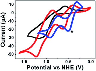
Scheme 1 shows the chemical structure and general synthetic procedure of [BMI]2[Co(NCS)4]. The details of the synthesis are described in Experimental section. It has already been demonstrated that redox potential plays a very important role in determining the photovoltaic performance of redox couples in DSSCs.12 Here, the cyclic voltammetry(CV) scans were calibrated using a ferrocene/ferrocenium (Fc/Fc+) couple, and the redox potentials were converted to those versus a normal hydrogen electrode (NHE) reference scale by adding a constant of 0.63 V as shown in Fig. 1.44 The redox potential of [Co2+(NCS)4]2−/[Co3+(NCS)4]− was determined to be 0.86 V versus NHE.In order to understand the redox behavior of this hybrid redox mediator, the CV of PMII/[BMI]2[Co(NCS)4] and PMII/I2 hybrid redox couples was studied too. The redox potentials of PMII/I2 and PMII/[BMI]2[Co(NCS)4] were determined to be 0.42 V and 0.50 V, respectively. Energy loss incurred during dye regeneration is one of the main factors limiting the performance of DSSCs.45 Since the redox potential of the dye is higher than that of the redox couple, a higher redox potential of redox mediator would reduce the excessive driving force for the dye-regeneration reaction and, therefore, beneficially improve the open-circuit voltage of the DSSC.46 Thus, it is not surprising that the PMII/[BMI]2[Co(NCS)4] hybrid redox couple yields the highest open-circuit voltage (Voc) of the devices fabricated.
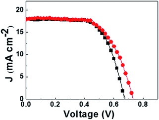
The photovoltaic parameters of DSSCs based on various redox couples under simulated AM 1.5 solar spectrum illumination at 100 mW cm−2 were measured (Fig. 2). The obtained photovoltaic data are summarized in Table 1. It can be clearly seen that the device based on the I−/I3− redox couple (Cell A) showed a short-circuit current density (Jsc) of 18.04 mA cm−2, a Voc of 674 mV, a fill factor (FF) of 64.1%, and an overall power efficiency of about 7.8%.
Ionic liquid (1-butyl-3-methylimidazolium tetrafluoroborate ([BMI][BF4])) electrolyte DSSCs based on PMII/[BMI]2[Co(NCS)4] hybrid redox were first studied. However, consider the poor fill factor (FF) and low efficiency of the devices (Fig. S1 and Table S1†), 3-methoxypropionitrile (MPN) was chosen as the solvent electrolyte for co-containing redox couple based DSSCs because of its superior advantages. In the case of the [Co2+(NCS)4]2−/[Co3+(NCS)4]−/I− hybrid redox couple (Cell B), the Voc value of the device was increased from 674 (Cell A) to 730 mV, and an average overall power conversion efficiency of 8.1% was achieved.
Cell C ([Co2+(NCS)4]2−/I− hybrid redox couple without addition of an oxidant NOBF4), Cell D (I− only without addition of I2) and Cell E (without addition of[Co2+(NCS)4]2−) were further assembled to compare the effects of hybrid redox couples on the cell performances. It can be seen that the power conversion efficiencies of Cells C, D and E are much lower than that of Cell B (Fig. S2†) probably due to the unbalanced redox couples.
Among the reported studies, none of the published work employing dual redox systems had clearly explained the electrochemical processes.47 Here, it can be seen from the redox potentials shown in Fig. 1 that I3− may be present as an intermediate in the hybrid redox system. Therefore, we hypothesize the redox mechanism functions as follows: (1) first, under light illumination, the photoexcitation of the dye (D) (eqn (1)) injects electrons into the conduction band of the TiO2 layer (eqn (2)). (2) Then the charge will transfer to the counter electrode (eqn (3)) and the oxidized molecular dye is restored to its ground state by electron donation from an electrolyte-containing redox system, reduced mainly by [Co2+(NCS)4]2− and formed [Co3+(NCS)4]− (eqn (4)). (3) The redox potential of the [Co(NCS)4]2− is more positive than that of the I−/I3− redox couple, I− is then easily reduced by [Co3+(NCS)4]− to I3− (eqn (5)). (4) After that, the electron injected into the conduction band arrives at the anode and then flows through the external load to the cathode. (5) Finally, I3− is reduced to iodide at the counter electrode (eqn (6)).
| D/TiO2 + hν → D*/DC | (1) |
| D*/DC → D+/TiO2 + ecb− | (2) |
| ecb− → ece− | (3) |
| D+/TiO2 + Co2+ → D/TiO2 + Co3+ | (4) |
| 2Co3+ + 3I− → I3− + 2Co2+ | (5) |
| I3− + 2ecb− → 3I− | (6) |
| ecb− + D* →D | (7) |
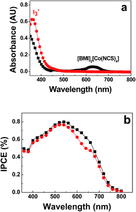
Fig. 3a shows the UV-Vis spectra of the electrolytes. It can be seen that the formation of I3− in PMII/BMI2[Co(NCS)4]/NOBF4 electrolyte is well hindered compared with PMII/I2 electrolyte. However, a low concentration of I3− in [Co2+(NCS)4]2−/[Co3+(NCS)4]− electrolyte did not result in a higher Jsc value probably due to the light absorption at around 600 nm of [BMI]2[Co(NCS)4] (Fig. 3a). The incident photo-to-current conversion efficiency (IPCE) spectra of Cell B and C were measured. As shown in Fig. 3b, Cell B showed slightly lower IPCE values compared with an I−/I3− redox couple in the visible spectrum, this can be attributed to the absorption of [BMI]2[Co(NCS)4] (between 560 and 670 nm).
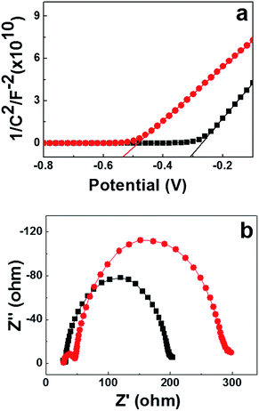
To better explain the higher Voc of the DSSCs based on the [BMI]2[Co(NCS)4] ionic liquid redox couple, the Mott–Schottky behavior of our TiO2 film/redox couple was obtained to determine flat-band potentials (Vfb; potential that induces zero net charge), as shown in Fig. 4a. The Voc of the cells is determined from the redox potential in the electrolyte and the quasi-Fermi level,48 which increases linearly with Vfb.49 A negative shift of Vfb in Fig. 4a means a shift away from the redox potential, thereby an increase of Voc. The conduction band of our TiO2 film with the PMII/[BMI]2[Co(NCS)4] hybrid electrolyte (Cell B) is about 215 mV positive that of the PMII/I2 based electrolyte (Cell A). Therefore, the Voc value of PMII/[BMI]2[Co(NCS)4] hybrid electrolyte is higher than that of the traditional I−/I3− redox couple electrolyte.
The electrochemical impedance spectroscopy (EIS) was further applied to examine the charge transfer resistance in DSSCs and for understanding recombination dynamics at the dye-coated TiO2/electrolyte interface. Cells A and B were measured at a bias of −0.7 V in the dark, as shown in Fig. 4b. From high to low frequency, three distorted semicircles are observed in the Nyquist plots. The distortions may be assigned to stretched exponential relaxation emanating from the fractal nature of the TiO2 porosity.50,51
Some important parameters could be obtained by fitting the EIS spectra to an electrochemical model (Table 2).52 RCE, RT and Rd represent the charge-transfer resistance at the counter electrode, the resistance of TiO2/FTO–TiO2/electrolyte interface, and the Nernst diffusion in electrolyte, respectively.6,53,54 It can be seen that the RCE value of Cell A is lower than that of Cell B, indicating that I−/I3− based electrolyte is easily reduced by the Pt counter electrode; this leads to a higher FF.47 Future studies will seek a suitable catalyst for deposition on the counter electrode to improve the fill factor using a PMII/[BMI]2[Co(NCS)4] redox couple. In general, the bigger the semicircle in the intermediate-frequency region, the weaker the charge recombination at the photoelectrode/electrolyte interface.55 The RT values of Cells A and B were calculated to be 166.7 Ω and 240.6 Ω, respectively. These results demonstrate that Cell B has a slower recombination reaction between the conduction band electrons in the TiO2 photoanode and electrolyte interface than Cell A. From Table 2, we can see that the value of Rd of Cell B is higher than that of Cell A, indicating an increase in the conductivity.56,57 Such a difference yields a higher photo conversion efficiency.44
| Cell | RCE/Ω | RT/Ω | Rd/Ω |
|---|---|---|---|
| A | 3.4 | 166.7 | 6.1 |
| B | 18.9 | 240.6 | 10.4 |
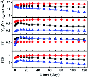
Consider the stability of our fabricated cells, the long-term stability test was carried out. The well sealed Cells (A, B, and E) were stored under dark conditions at room temperature. The photovoltaic performance parameters including Jsc, Voc, FF and PCE of the cells were measured daily and the photovoltaic parameters of these DSSCs are shown in Fig. 5. In the case of the I−/I3− redox couple (Cell A), the device exhibited an initial improvement in performance (PCE), but then there was a gradual decrease that stabilized at about 95% of the original value after 120 day. However, a slight increase (∼10%) of PCE was observed for DSSCs based on PMII/[BMI]2[Co(NCS)4]/TBP electrolyte (Cell B) throughout the 120 day stability testing. The highest overall efficiency of 8.9% under 1.5 solar spectrum illumination at 100 mW cm−2 was obtained on the 30th day of testing (Fig. S3†). For comparison, Cell E, a device containing the same electrolyte as Cell B (however, without TBP), was fabricated and characterized under the same experimental conditions. It can be seen that a decrease in performance of about 10% was observed for Cell E after 120 day testing. Above all, we conclude that the relatively high stability of Cell B is due to the presence of TBP (as compared with Cell E).
According to the recently studied by Bach and co-workers,58 additives the long-term stability of the co-bpy electrolyte based DSSCs.59 It should be noted that the concentration of TBP (0.8 M) in the electrolyte is much higher than that of [BMI]2[Co(NCS)4] (0.2 M). Therefore, [BMI]2[Co(NCS)4] could be replaced by a more strongly binding [BMI]2[Co(NCS)4(TBP)2] ligand (Scheme S1†). Such a multidentate ligand may form a very stable cobalt redox mediator under DSSC test conditions. This is the first reported example where such a cobalt-based hybrid electrolyte has provided such excellent device stability; the mechanism behind our observations was still under exploration.
Conclusion
In conclusion, a cobalt-containing room temperature ionic liquid, [BMI]2[Co(NCS)4], was synthesized and for the first time applied as a redox mediator in DSSC electrolytes. The fabricated devices based on this [BMI]2[Co(NCS)4]/PMII hybrid redox couple and TBP exhibited a power conversion efficiency of 8.1% under AM 1.5 solar spectrum illumination at 100 mW cm−2. In addition, the devices tested in this study exhibited excellent long-term stability under ambient conditions over 120 days. Further investigations will focus on the structure–activity optimization of cobalt-containing ionic liquid-based redox mediators, as well as long-term device stability.Acknowledgements
This work was supported by the National Science Foundation for Distinguished Young Scholars (No. 21425417), the Natural Science Foundation of China (No. 21274101), and the Project Funded by the Priority Academic Program Development of Jiangsu Higher Education Institutions.References
- B. Oregan and M. Gratzel, Nature, 1991, 353, 737–740 CrossRef CAS.
- M. Gratzel, Nature, 2001, 414, 338–344 CrossRef CAS PubMed.
- Y. Zhang, H. Li, L. Kuo, P. Dong and F. Yan, Curr. Opin. Colloid Interface Sci., 2015, 20, 406–415 CrossRef CAS.
- B. He, Q. Tang, J. Luo, Q. Li, X. Chen and H. Cai, J. Power Sources, 2014, 256, 170–177 CrossRef CAS.
- T. Deepak, G. Anjusree, S. Thomas, T. Arun, S. V. Nair and A. S. Nair, RSC Adv., 2014, 4, 17615–17638 RSC.
- Y. Zhang, Z. Sun, S. Cheng and F. Yan, ChemSusChem, 2016, 9, 813–819 CrossRef CAS PubMed.
- G. Boschloo and A. Hagfeldt, Acc. Chem. Res., 2009, 42, 1819–1826 CrossRef PubMed.
- J. Cong, X. Yang, L. Kloo and L. Sun, Energy Environ. Sci., 2012, 5, 9180–9194 CAS.
- T. Daeneke, T. H. Kwon, A. B. Holmes, N. W. Duffy, U. Bach and L. Spiccia, Nat. Chem., 2011, 3, 211–215 CrossRef CAS PubMed.
- T. Daeneke, A. J. Mozer, T.-H. Kwon, N. W. Duffy, A. B. Holmes, U. Bach and L. Spiccia, Energy Environ. Sci., 2012, 5, 7090–7099 CAS.
- S. A. Sapp, C. M. Elliott, C. Contado, S. Caramori and C. A. Bignozzi, J. Am. Chem. Soc., 2002, 124, 11215–11222 CrossRef CAS PubMed.
- J.-H. Yum, E. Baranoff, F. Kessler, T. Moehl, S. Ahmad, T. Bessho, A. Marchioro, E. Ghadiri, J.-E. Moser, C. Yi, M. K. Nazeeruddin and M. Graetzel, Nat. Commun., 2012, 3, 631 CrossRef PubMed.
- M. Xu, D. Zhou, N. Cai, J. Liu, R. Li and P. Wang, Energy Environ. Sci., 2011, 4, 4735–4742 CAS.
- I. R. Perera, T. Daeneke, S. Makuta, Z. Yu, Y. Tachibana, A. Mishra, P. Bäuerle, C. A. Ohlin, U. Bach and L. Spiccia, Angew. Chem., Int. Ed., 2015, 54, 3758–3762 CrossRef CAS PubMed.
- Z. Sun, M. Liang and J. Chen, Acc. Chem. Res., 2015, 48, 1541–1550 CrossRef CAS PubMed.
- A. V. Muller, L. D. Ramos, K. P. M. Frin, K. T. de Oliveira and A. S. Polo, RSC Adv., 2016, 6, 46487–46494 RSC.
- Y. Bai, Q. Yu, N. Cai, Y. Wang, M. Zhang and P. Wang, Chem. Commun., 2011, 47, 4376–4378 RSC.
- T. E. Hewat, L. J. Yellowlees and N. Robertson, Dalton Trans., 2014, 43, 4127–4136 RSC.
- A. Buttner, S. Y. Brauchli, R. Vogt, E. C. Constable and C. E. Housecroft, RSC Adv., 2016, 6, 5205–5213 RSC.
- B. V. Bergeron, A. Marton, G. Oskam and G. J. Meyer, J. Phys. Chem. B, 2005, 109, 937–943 CrossRef CAS PubMed.
- P. Wang, S. M. Zakeeruddin, J. E. Moser, R. Humphry-Baker and M. Gratzel, J. Am. Chem. Soc., 2004, 126, 7164–7165 CrossRef CAS PubMed.
- X. Liu, Z. Cao, H. Huang, X. Liu, Y. Tan, H. Chen, Y. Pei and S. Tan, J. Power Sources, 2014, 248, 400–406 CrossRef CAS.
- D. Xu, H. Zhang, X. Chen and F. Yan, J. Mater. Chem. A, 2013, 1, 11933–11941 CAS.
- X. Chen, D. Xu, L. Qiu, S. Li, W. Zhang and F. Yan, J. Mater. Chem. A, 2013, 1, 8759–8765 CAS.
- H. Nusbaumer, J. E. Moser, S. M. Zakeeruddin, M. K. Nazeeruddin and M. Gratzel, J. Phys. Chem. B, 2001, 105, 10461–10464 CrossRef CAS.
- M. Ye, X. Wen, M. Wang, J. Iocozzia, N. Zhang, C. Lin and Z. Lin, Mater. Today, 2015, 18, 155–162 CrossRef CAS.
- K. Kakiage, Y. Aoyama, T. Yano, K. Oya, J.-i. Fujisawa and M. Hanaya, Chem. Commun., 2015, 51, 15894–15897 RSC.
- A. Yella, H.-W. Lee, H. N. Tsao, C. Yi, A. K. Chandiran, M. K. Nazeeruddin, E. W.-G. Diau, C.-Y. Yeh, S. M. Zakeeruddin and M. Graetzel, Science, 2011, 334, 629–634 CrossRef CAS PubMed.
- T. Peppel, M. Koeckerling, M. Geppert-Rybczynska, R. V. Ralys, J. K. Lehmann, S. P. Verevkin and A. Heintz, Angew. Chem., Int. Ed., 2010, 49, 7116–7119 CrossRef CAS PubMed.
- B. Mallick, B. Balke, C. Felser and A.-V. Mudring, Angew. Chem., Int. Ed., 2008, 47, 7635–7638 CrossRef CAS PubMed.
- Z.-L. Xie, A. Jelicic, F.-P. Wang, P. Rabu, A. Friedrich, S. Beuermann and A. Taubert, J. Mater. Chem., 2010, 20, 9543–9549 RSC.
- S. Tang, A. Babai and A.-V. Mudring, Angew. Chem., Int. Ed., 2008, 47, 7631–7634 CrossRef CAS PubMed.
- Z.-L. Xie, H.-B. Xu, A. Gessner, M. U. Kumke, M. Priebe, K. M. Fromm and A. Taubert, J. Mater. Chem., 2012, 22, 8110–8116 RSC.
- K. Lunstroot, K. Driesen, P. Nockemann, L. Viau, P. H. Mutin, A. Vioux and K. Binnemans, Phys. Chem. Chem. Phys., 2010, 12, 1879–1885 RSC.
- L. Li, Y. Yang, R. Fan, Y. Jiang, L. Wei, Y. Shi, J. Yu, S. Chen, P. Wang and B. Yang, J. Power Sources, 2014, 264, 254–261 CrossRef CAS.
- P. Zhang, Y. Gong, Y. Lv, Y. Guo, Y. Wang, C. Wang and H. Li, Chem. Commun., 2012, 48, 2334–2336 RSC.
- A. Chinnappan, H. Kim, C. Baskar and I. T. Hwang, Int. J. Hydrogen Energy, 2012, 37, 10240–10248 CrossRef CAS.
- A. Branco, L. C. Branco and F. Pina, Chem. Commun., 2011, 47, 2300–2302 RSC.
- A. Babai, S. Pitula and A.-V. Mudring, Eur. J. Inorg. Chem., 2010, 4933–4937 CrossRef CAS.
- J. Wu, Z. Tang, Y. Huang, M. Huang, H. Yu and J. Lin, J. Power Sources, 2014, 257, 84–89 CrossRef CAS.
- Y. Zhang, Z. Sun, C. Shi and F. Yan, RSC Adv., 2016, 6, 70460–70467 RSC.
- H. Li, S. Li, Y. Zhang and F. Yan, RSC Adv., 2016, 6, 346–352 RSC.
- M. K. Nazeeruddin, A. Kay, I. Rodicio, R. Humphry-Baker, E. Mueller, P. Liska, N. Vlachopoulos and M. Graetzel, J. Am. Chem. Soc., 1993, 115, 6382–6390 CrossRef CAS.
- H. Tian, X. Jiang, Z. Yu, L. Kloo, A. Hagfeldt and L. Sun, Angew. Chem., Int. Ed., 2010, 49, 7328–7331 CrossRef CAS PubMed.
- R. Bajpai, S. Roy, P. Kumar, P. Bajpai, N. Kulshrestha, J. Rafiee, N. Koratkar and D. S. Misra, ACS Appl. Mater. Interfaces, 2011, 3, 3884–3889 CAS.
- J.-H. Yum, E. Baranoff, F. Kessler, T. Moehl, S. Ahmad, T. Bessho, A. Marchioro, E. Ghadiri, J.-E. Moser and C. Yi, Nat. Commun., 2012, 3, 631 CrossRef PubMed.
- J. Liu, X. Yang, J. Cong, L. Kloo and L. Sun, Phys. Chem. Chem. Phys., 2012, 14, 11592–11595 RSC.
- A. Hagfeldt, G. Boschloo, L. Sun, L. Kloo and H. Pettersson, Chem. Rev., 2010, 110, 6595–6663 CrossRef CAS PubMed.
- M.-H. Kim and Y.-U. Kwon, J. Phys. Chem. C, 2009, 113, 17176–17182 CAS.
- M. F. Shlesinger and E. W. Montroll, Proc. Natl. Acad. Sci. U. S. A., 1984, 81, 1280–1283 CrossRef CAS.
- J. Texter and M. Lelental, Langmuir, 1999, 15, 654–661 CrossRef CAS.
- F. Fabregat-Santiago, J. Bisquert, G. Garcia-Belmonte, G. Boschloo and A. Hagfeldt, Sol. Energy Mater. Sol. Cells, 2005, 87, 117–131 CrossRef CAS.
- J. Dong, J. H. Wu, J. B. Jia, L. Q. Fan, Z. Lan, J. M. Lin and Y. L. Wei, J. Power Sources, 2016, 336, 83–90 CrossRef CAS.
- J. H. Huo, J. H. Wu, M. Zheng, Y. G. Tu and Z. Lan, Electrochim. Acta, 2016, 187, 210–217 CrossRef CAS.
- S. M. Feldt, G. Wang, G. Boschloo and A. Hagfeldt, J. Phys. Chem. C, 2011, 115, 21500–21507 CAS.
- H. Dong, Z. Wu, A. El-Shafei, B. Xia, J. Xi, S. Ning, B. Jiao and X. Hou, J. Mater. Chem. A, 2015, 3, 4659–4668 CAS.
- Y. Zhang, N. Zhou, K. Zhang and F. Yan, J. Power Sources, 2017, 342, 292–300 CrossRef CAS.
- M. K. Kashif, J. C. Axelson, N. W. Duffy, C. M. Forsyth, C. J. Chang, J. R. Long, L. Spiccia and U. Bach, J. Am. Chem. Soc., 2012, 134, 16646–16653 CrossRef CAS PubMed.
- M. K. Kashif, M. Nippe, N. W. Duffy, C. M. Forsyth, C. J. Chang, J. R. Long, L. Spiccia and U. Bach, Angew. Chem., Int. Ed., 2013, 52, 5527–5531 CrossRef CAS PubMed.
Footnotes |
| † Electronic supplementary information (ESI) available: 1H NMR characterization of the synthesized compounds and TGA analysis of prepared AEMs. See DOI: 10.1039/c6ra26402f |
| ‡ Authors with equal contributions. |
| This journal is © The Royal Society of Chemistry 2017 |


![[thin space (1/6-em)]](https://www.rsc.org/images/entities/char_2009.gif) :
: