DOI:
10.1039/C6RA25980D
(Paper)
RSC Adv., 2017,
7, 8106-8117
Two magnon scattering and anti-damping behavior in a two-dimensional epitaxial TiN/Py(tPy)/β-Ta(tTa) system†
Received
28th October 2016
, Accepted 16th January 2017
First published on 23rd January 2017
Abstract
The prime requirements for the spin transfer torque based ferromagnetic (FM)/nonmagnetic (NM) bilayer spin devices are (i) the absence of two-magnon scattering (TMS) noise, (ii) minimum energy dissipation and (iii) fast switching. To realize these objectives we have studied the thickness, Py (permalloy) thicknesses (tPy) and β-Ta thicknesses (tTa), dependent magnetization dynamics behaviour of the epitaxial Py (tPy = 3–20 nm)/β-Ta (tTa = 1.5–15 nm) system. The tPy dependence of TMS in epitaxial Py nano-layers (tPy = 3–20 nm) grown on a Si(400)/TiN(200) (8 nm) substrate is explored in terms of uniform and non-uniform magnetization precession regimes by employing ferromagnetic resonance field (Hr), line-width (ΔH), and Gilbert damping constant (α) behaviour. It is found that in Py, tPy < 10 nm, layers TMS is dominating due to non-uniform precession of the magnetization. However in Py, tPy ≥ 10 nm, layers the uniform magnetization precession dominates, therefore Py layers, tPy ≥ 10 nm, are almost free from TMS. Furthermore, a nearly TMS free 12 nm epitaxial Py(200) layer is capped with β-Ta (tTa = 1.5–15 nm) layers to explore the tTa dependent magnetization precession of epitaxial Py (12 nm) in terms of change in effective Gilbert damping constant (αeff). An anomalous decrease in αeff from 0.0087 at tTa = 0 to a minimum value of 0.0077 at tTa = 6 nm, and its subsequent increase for tTa > 6 nm are observed in the epitaxial Py (12 nm)/β-Ta(tTa) system. Therefore the Si(400)/TiN(200) (8 nm)/Py(200) (12 nm)/β-Ta(200) (6 nm) epitaxial system with nearly uniform magnetic precession and minimum effective Gilbert damping is suitable for low energy loss and ultrafast switching applications in spin transfer torque devices.
Introduction
Employing spin current without charge current is of great interest in the development of spin transfer torque (STT) devices.1 A bilayer consisting of ferromagnetic (FM)/non-magnetic (NM) layers is one of the most reliable material architectures to fundamentally investigate the STT mechanism and its role in devices.2–7 Owing to the presence of structural inversion asymmetry among the two dissimilar materials at the FM/NM interface, an important physical phenomenon known as the Rasbha effect results when a charge current flows through the bilayer, wherein the spin–orbit Hamiltonian breaks the degeneracy in the electron spin states at the interface and creates a non equilibrium spin accumulation.8 This non-equilibrium spin accumulation acts like a spin–orbit torque (SOT) on the magnetization precession of the FM layer.8,9 Thus, the Rashba effect gives rise to a spin–orbit torque (SOT) which plays a critical role in the FM/NM bilayer systems by enhancing the efficiency of STT in potential device applications.8,9 The SOT arises from the non-equilibrium spin accumulation at interface in presence of strong spin–orbit interaction (SOI) of NM layer in FM/NM bilayer system.10 The spin-pumping induced spin accumulation creates a non-equilibrium spin density in the adjacent NM layer near the FM/NM interface. Thus in FM/NM bilayer system two types of spin–orbit torque exist, (i) interfacial spin–orbit coupling (ISOC) torque due to Rashba effect and (ii) bulk spin–orbit coupling (BSOC) torque due to spin Hall effect or spin accumulation in NM layer.11,12 Therefore the net torque acting on the FM layer in FM/NM bi-layer system can be represented as, ![[T with combining right harpoon above (vector)]](https://www.rsc.org/images/entities/i_char_0054_20d1.gif) = (TISOC + TBSOC)⊥[ŷ ×
= (TISOC + TBSOC)⊥[ŷ × ![[m with combining circumflex]](https://www.rsc.org/images/entities/i_char_006d_0302.gif) ] + (TISOC + TBSOC)∥[ × ŷ × ], where ŷ is the spin polarization direction and is magnetization direction. Here (TISOC + TBSOC)⊥ is the field-like (or out of plane) toque, and (TISOC + TBSOC)∥ is the anti-damping (or in-plane) torque,11,12 both having contributions from interfacial and bulk spin–orbit couplings. The field-like toque is exchange-coupled torque, and apart from its Rashba origin it also can have origin in a non-adiabatic spin transfer torque. The field-like torque enhances the precession of the magnetization of the FM layer at high current density.13 On the other hand, anti-damping torque is predominantly Slonczewski Berger spin-transfer torque,14 and it can also have contribution from spin flip reflection at the interface.10–13,15 Thus, ISOC and BSOC induced torque play crucial role in realizing low power magnetization switching,5 high speed domain wall motion,16–18 tunable nano oscillators,4,19 etc. They also help in reducing the writing energy and improving device life time.18,19
] + (TISOC + TBSOC)∥[ × ŷ × ], where ŷ is the spin polarization direction and is magnetization direction. Here (TISOC + TBSOC)⊥ is the field-like (or out of plane) toque, and (TISOC + TBSOC)∥ is the anti-damping (or in-plane) torque,11,12 both having contributions from interfacial and bulk spin–orbit couplings. The field-like toque is exchange-coupled torque, and apart from its Rashba origin it also can have origin in a non-adiabatic spin transfer torque. The field-like torque enhances the precession of the magnetization of the FM layer at high current density.13 On the other hand, anti-damping torque is predominantly Slonczewski Berger spin-transfer torque,14 and it can also have contribution from spin flip reflection at the interface.10–13,15 Thus, ISOC and BSOC induced torque play crucial role in realizing low power magnetization switching,5 high speed domain wall motion,16–18 tunable nano oscillators,4,19 etc. They also help in reducing the writing energy and improving device life time.18,19
However it has been recently reported that Rashba SOT occurs in FM/NM bilayer system because of non-equilibrium spin accumulation nearer to the interface. These non-equilibrium spins accumulate at the interface either by SHE phenomena with application of charge current in NM layer19 or from the spin pumping from FM layer in the absence of any external dc current in FM/NM bilayer system or inversion symmetry breaking at the interface.20–26 These accumulated spins do not dissipate their angular momentum in the NM layer within the thickness limits of spin diffusion length (λSD).14,23,24,27 Thus the choice of NM layer for the Rashba and BSOC SOT mechanisms is significant for efficient pure spin current based new generation spintronic devices. Since β-Ta has spin accumulation property along with high −ve spin Hall angle (∼2 times that in Pt) and high SOI value (comparable to that in Pt).6,21 It provides an attractive alternative to Pt as heavy metal NM layer for SOT phenomena. Study on Py/β-Ta bilayers with polycrystalline Py reported that as the β-Ta layer thickness is varied a lowering of damping is observed.26 As already stated the Rashba SOT phenomenon can be studied efficiently when the FM layer is undergoing uniform magnetization precession.13,28–30 It is therefore imperative to focus and improve upon the quality as well as tune the thickness of FM layer such that the uniform precession of magnetization (known as Gilbert type of relaxation) should exist without any interruption arising due to extrinsic effects that lead to non-uniform magnetization-precession (non-Gilbert types of relaxation).31,32 These extrinsic effects could be either the presence of surface anisotropy field, or magnetic inhomogeneity, or dipolar coupling field between the magnetic moments, all of which make the magnetization precession of FM layer increasingly non-uniform in nature resulting in two magnon scattering (TMS) phenomena.31,32 In the TMS process, the uniform magnetization precession at a particular frequency is annihilated and another spin wave magnon of the same frequency (akin to discrete quantum modes) is created which leads to the enhancement in FMR linewidth and hence in the damping of magnetization precession.31–33 To avoid such undesirable features that add to the Gilbert damping constant, it seems necessary to concentrate on appropriate thickness of epitaxial Py FM layer such that the uniform precession of magnetization should exist. Thus, the critical film thickness regime needs to be carefully identified for minimization of extrinsic TMS contribution. In this work, we therefore have focused on epitaxial permalloy (Py) FM layer of thickness up to 20 nm, with the use of Si(100) wafer/8 nm TiN(200) substrate instead of using Si/SiO2 substrate (where SiO2 is a native oxide layer). Here epi-TiN acts as buffer layer useful for minimizing the lattice mismatch problem between Si substrate and Py layer.34,35 TiN is a material which has high conductivity and low spin–orbit coupling strength. The spin diffusion length in TiN is 43 nm.36 The growth of TiN(200) layer occurs by domain epitaxy process.34 Then we optimize the particular thickness regime of Py layer so that the TMS contribution is minimum. After that we studied the effect of β-Ta layer thickness (1.5–15 nm) on the magnetization precession of Py layer in TiN(200)/Py(200)/β-Ta system. It is not only technologically important but also of fundamental interest to explore the role of β-Ta layer on the SOT mechanism. We discuss the detailed results related with the observed anti-damping behavior of TiN/Py/β-Ta multilayers in terms of the changes in the effective Gilbert damping constant of uniformly magnetized epi-Py layer of appropriate thickness as a function of the β-Ta layer film thickness with naturally formed β-Ta2O5 oxide interface (Ta2O5 layer (∼2 nm) is formed naturally after the exposure to ambient). The results are organized in three different sections; (A) the growth of epitaxial Py (3–20 nm) on 8 nm epitaxial TiN buffer, (B) study of the magnetization dynamics in these epitaxial Py samples to investigate the thickness dependent TMS, and (C) study of the β-Ta layer thickness (1.5–15 nm) dependent effective Gilbert damping constant in TiN(200)/Py(200)/β-Ta bilayers.
Experimental
Two different sets of samples were prepared for the present studies. In the first set, Py (Ni81Fe19) thin films of different thicknesses 3–20 nm were grown on epitaxial TiN buffered Si substrates by pulsed DC magnetron sputtering using 99.99% pure Py target room temperature. While the base pressure of sputtering chamber was ∼2 × 10⁻⁷ Torr, the sputtering was performed in the Ar environment maintained at a working pressure of 3.2 × 10⁻³ Torr. Prior to deposition, the Si substrates were treated to remove the native SiO2 layer by dipping it into 5% HF solution for 1 min. Subsequently, the epitaxial TiN films were grown on these Si substrates at 750 °C in presence of N2 partial pressure of 5 × 10⁻⁵ Torr.35 In the second set, β-Ta layers of different thicknesses varying from 1.5 to 15 nm were grown on the epitaxial Si(100)/TiN(8 nm)/Py(12 nm). The growth of β-Ta(200) oriented films were made by employing pulsed dc magnetron sputtering using 99.99% pure Ta target at room temperature. During the growth the Ar gas pressure was maintained at 3.2 × 10⁻³ Torr. The films were grown at 150 W (∼0.2 nm s−1) sputtering power. The measured values of resistivity of these films, lying in the range of 180–190 μΩ cm, matched excellently well with the reported value of β-phase Ta in literature.5,11 Substrate surface and the growing films were monitored by the high pressure reflection high energy electron diffraction (RHEED) of STAIB Instruments, and RHEED patterns were analyzed using KSA-400 software. Before the deposition, the substrates were heated at 750 °C. The clear RHEED patterns observed after the heat treatment ensured the cleanliness of the substrate surface. The crystal structure analyses were performed using X'Pert-Pro X-ray Diffractometer (XRD) with Cu-Kα (1.54 Å) source. The thicknesses of individual layers and interface roughness (∼0.4 nm) were accurately determined from the XRR measurements. X-ray photoelectron spectroscopic (XPS) spectra were recorded using SPECS make system which uses Al-Kα (1486.6 eV) source and hemispherical energy analyzer (pass energy of 40 eV with a resolution of ∼0.3 eV) to probe the surface of the Py/β-Ta bilayers. The in-plane magnetization measurements of Py/β-Ta thin films were measured by using Vibrating sample magnetometer option of Physical Property Measurement System (Model Evercool II, Quantum Design Inc.). The resonance field Hr and line width ΔH were measured by using broadband lock-in amplifier (SR-830) based ferromagnetic resonance (LIA-FMR) technique with the help of a 8719ES vector network analyzer (VNA) in the in-plane magnetic field configuration (along the easy magnetization direction) employing a coplanar wave guide (CPW). The dc-magnetic field was modulated with a 211.5 Hz ac-field of 1.3 Oe strength using a pair of Helmholtz coils.
Results and discussion
A. RHEED and Structural analyses of Py on epitaxial TiN
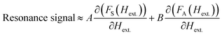
The RHEED pattern recorded on bare Si(100) along the [001] direction is shown in Fig. 1(a). The sharp streaky pattern with Kikuchi lines clearly confirms the clean and stable (2 × 1) reconstructed Si surface. Fig. 1(b) shows the RHEED pattern recorded along [001] direction on TiN(200) film grown on (2 × 1) reconstructed Si(100) substrate. Regardless of the ∼22.4% lattice misfit of TiN with Si(100), presence of prolonged streaks confirm the epitaxial growth of TiN(200) on Si(100) which is also confirmed by XRD and will be discussed in the next section. This has been possible by domain epitaxy34 because of a specific orientation relationship in which 5 unit cells of TiN (a = 4.24 Å) match with 4 unit cells of Si (a = 5.43 Å), which reduces the overall mismatch to 2.4% and hence Si(400)//TiN(200); Si[001]//TiN[001] epitaxial growth occurs.35 The Py layers of different thicknesses in 3–20 nm range were deposited on TiN buffered Si(100). 2-D epitaxial growth was seen to occur for Py layer thicknesses ≥ 12 nm. Fig. 1(c)–(e) show the RHEED patterns recorded along [001] direction for 20, 12, 7 nm Py layer samples, respectively. The evolution of elongated and sharp streaks with the increase in the Py layer thickness confirms the improvement in epitaxial quality of the Py layers. Similar RHEED patterns are also observed along [010] direction (not shown here for brevity). Thus, the RHEED patterns along [001] and [010] clearly confirm the in-plane epitaxial TiN(200)//Py(200); TiN[001]//Py[001] orientation relationship of these samples.
 |
| | Fig. 1 The RHEED patterns along [001] of (a) cleaned Si(100) substrate, (b) TiN 8 nm, (c) Py 20 nm, (d) Py 12 nm, and (e) Py 7 nm samples. (f) Typical θ–2θ XRD pattern of epitaxial TiN (8 nm)/Py (tPy nm) films on Si(100) substrate showing high crystalline quality, single phase Py with (200) orientation. (g) shows the ω-scan XRD of 20, 15, and 12 nm Py samples. | |
To further investigate the crystallographic orientation of Py (tPy nm) thin films, where tPy corresponds to thickness of Py layer, the θ–2θ scans and rocking ω-scans were also recorded. The θ–2θ scans of the bilayer TiN/Py samples are shown in Fig. 1(f). The observed diffraction peak from the (200) planes of Py layer on TiN(200) together with the RHEED analysis further confirmed the epitaxial Si(400)/TiN(200)/Py(200) orientation relationship of all the samples. As expected, these samples did not show any diffraction peak in glancing angle XRD measurements (data not shown for brevity). The ω-scan XRD profiles (Fig. 1(g)) recorded on these samples clearly suggest that the increase in Py layer thickness leads to the enhancement in the crystalline quality. Also, the presence of relatively sharp and streaky RHEED patterns confirms the changeover of the epitaxial growth from three dimensional (tPy < 10 nm) to two-dimensional (tPy ≥ 10 nm) as shown Fig. 1 in ESI file.†
B. Study of the magnetization dynamics of epitaxial Py thin films
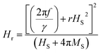
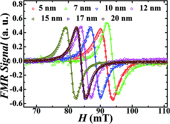
To explore the spin dynamic response in these samples, the FMR spectra were recorded by sweeping the external magnetic field from higher to lower values at different constant frequencies in the range of 5 to 10 GHz. The FMR measurements are performed on the epitaxial Si/TiN (8 nm)/Py (tPy nm) system to identify the thickness regime of the Py layer for which the ΔH is minimum so as to have a tradeoff between film thickness and low extrinsic contributions. The details of measurement setup are given in ref. 26. The FMR absorption spectra were recorded on different samples of the Si(100)/TiN (8 nm)/Py (tPy nm) series, where tPy ranges in 3–20 nm. For clarity and conciseness, Fig. 2 shows the FMR absorption curves recorded at one of the frequencies (9 GHz) for the different samples. Each of the FMR spectrum is fitted with sum of the derivatives of symmetric and antisymmetric Lorentzian functions, as shown by the solid lines in Fig. 2, to determine the values of in-plane ΔH and Hr, using:6| |
 | (1) |
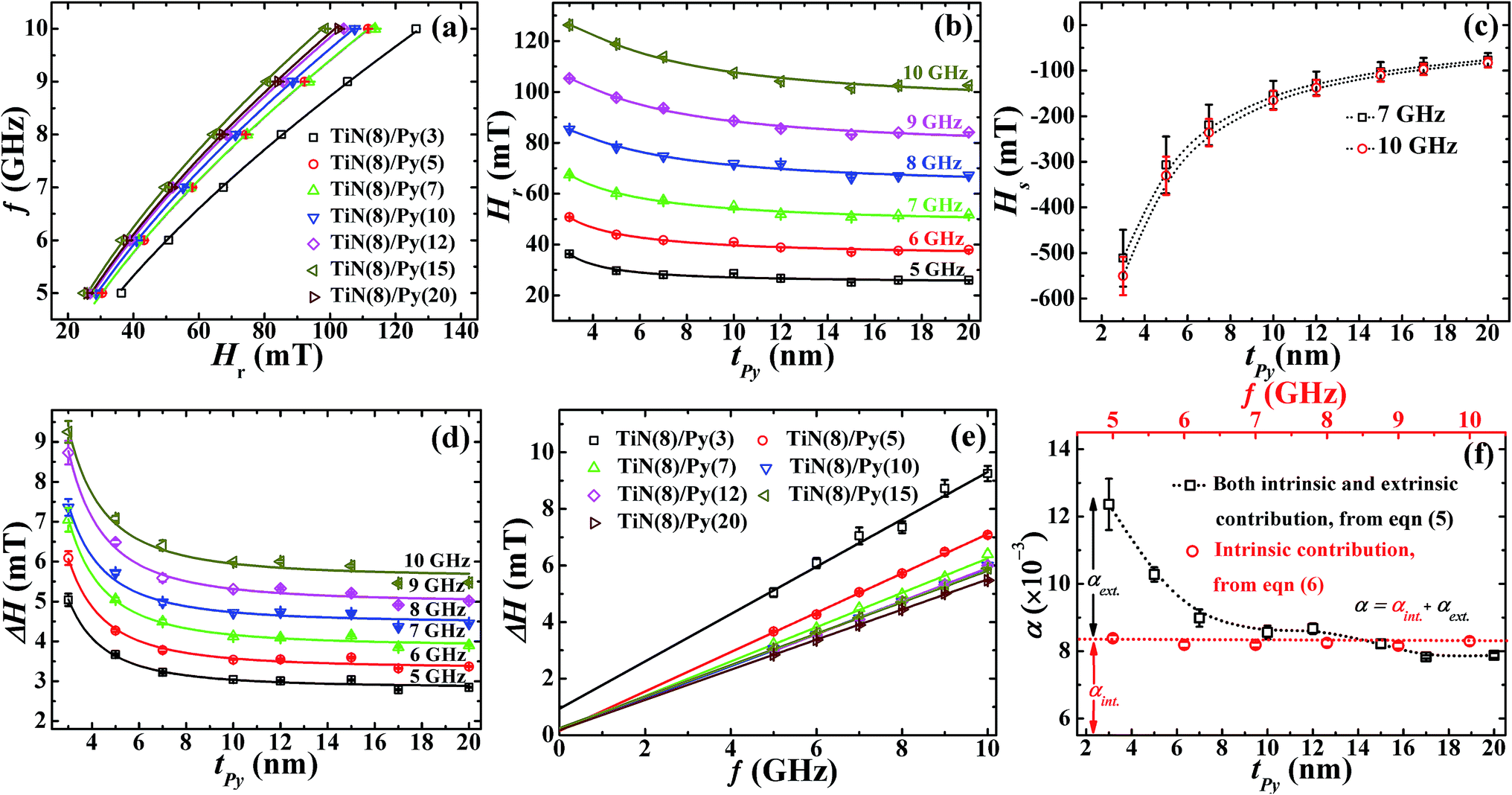
here, FS(Hext.) = ΔH2/{ΔH2 + (Hext. − Hr)2}, and FA(Hext.) = FS(Hext.){(Hext. − Hr)/ΔH} are symmetric and antisymmetric Lorentzian functions, respectively, with constants A and B as their corresponding coefficients. When fitted using eqn (1), it is found that the observed FMR spectra are of completely symmetric Lorentzian shape, and the antisymmetric Lorentzian coefficients are found to be very small as compared to symmetric Lorentzian coefficient (by a factor of 100 or more). The frequency and thickness dependences of the observed line shape parameters (Hr and ΔH) are plotted in Fig. 3. To understand the observed variation of in-plane Hr with the resonance frequency f for series of samples (tNM: 3–20 nm) the observed line shape parameters are fitted by using the Kittel's eqn;37| |
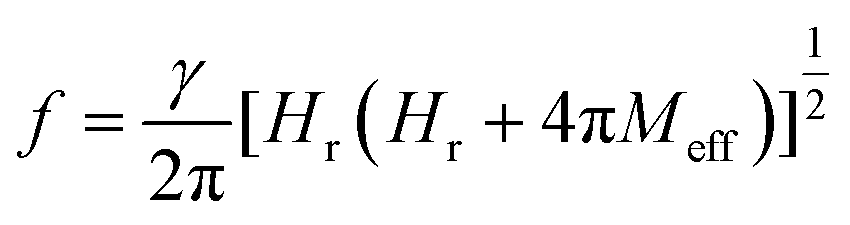
 | (2) |
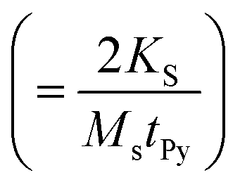
where, γ is the gyromagnetic ratio (=1.856 × 10¹¹ Hz T−1), 4πMeff is the effective magnetization field, which is given by: 4πMeff = 4πMs + HS. Here HS is the surface anisotropy field  which is induced by the surface and interfacial defects and also by the anisotropic orbital angular momentum,38 4πMs is the saturation magnetization of Py layer, and KS is the surface anisotropy energy constant. The value of 4πMs, as determined from the fitting of 4πMeff vs. tPy data using the expression
  , is found to be 1088 (±19) mT (see Fig. ESI5(a)†). The 4πMs value obtained from FMR measurements is consistent with the value of 1195 (±100) mT obtained from VSM measurements.39 Here it is to be noted that one can't directly extract the HS from the effective magnetization because HS is also affected by shift in the Hr with respect to tPy.40 Fig. 3(a) shows the variation of Hr with f for different Py(tPy) films, and this observed variation is fitted to eqn (2). The fitted values of 4πMeff are found to vary from 772 mT to 1028 mT as Py thickness increases from 3 to 20 nm (see Fig. ESI5a†). Fig. 3(b) shows a shift in the resonance field Hr on increasing tPy corresponding to different constant resonance frequencies. This shift can be linked with the nature of resonance mode associated with the samples. To explain this tPy dependence of Hr, we utilized the following expression,37
| |
 | (3) |
where the 2nd term in the eqn (3) represents the TMS induced shift in the resonance field, and is well explained by theory given by Arias and Mills.32 The “r” is the magnon renormalization factor which has units of T−1. However, in our case Hr ≪ 4πMs, therefore the eqn (3) can be rewritten as;| |
 | (4) |
 |
| | Fig. 2 The FMR absorption curves (experimental data in open symbols) of TiN (8 nm)/Py (tPy nm) at 9 GHz, where tPy is the thickness of epitaxial Py layer over the range of 5–20 nm. The solid lines represent the fitted curves. | |
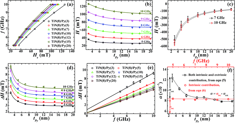 |
| | Fig. 3 The experimental data (open symbols) of (a) the frequency (f) dependence in-plane resonance field (Hr) i.e. f vs. Hr for TiN (8 nm)/Py (tPy) series of samples, and solid lines show the fitting according to Kittel's eqn (2). (b) Thickness dependence of resonance field Hr i.e. Hr vs. tPy at different constant resonance frequencies and solid lines show the fitting using eqn (4). (c) The thickness dependence of HS i.e. HS vs. tPy is obtained from the fitting using eqn (4) for TiN (8 nm)/Py (tPy) at different constant resonance frequencies. (d) Thickness dependence of ΔH i.e. ΔH vs. tPy for TiN (8 nm)/Py (tPy) at different constant frequencies, and solid lines show the fitting using eqn (6). (e) The frequency dependence of line broadening ΔH i.e. ΔH vs. f for different tPy samples, and solid lines are fitting using eqn (5). (f) The effect of tPy on the overall damping constant α (open black squares) obtained from eqn (5) and the intrinsic Gilbert damping constant αint. (red open circles) obtained from eqn (6) for the epitaxial Py films. Note that the αext. damping comes from the extrinsic TMS contribution and can be inferred by using α = αint. + αext. (the dotted lines are guide to the eye). | |
The tPy dependence of Hr at different constant frequencies in 5–10 GHz range is fitted using this eqn (4), as shown by solid lines in Fig. 3(b). The various fitting parameters are presented in Table 1 of ESI file.† The fitted values of ‘r’ lie in the range of 8.85 × 10⁻⁵ mT−1 to 2.10 × 10⁻⁴ mT−1. These values are close to the value 8 × 10⁻⁵ mT−1 reported previously on the basis of theory that accounts for the field shift data.32,40 The estimated values of HS are found to change from −551 mT to −82 mT for 10 GHz frequency (and from −511 to −77 mT for 7 GHz frequency) as the tPy is increased from 3 to 20 nm, as shown in Fig. 3(c). While a gradual decrease in Hr and HS are observed with increase in tPy in low thickness regime (3–10 nm range), the changes in Hr and HS become insignificant as tPy is increased above ∼12 nm. In the previous study,33 the higher HS value observed at lower tPy is attributed to the presence of local microscopic surface inhomogeneities in the sample. Thus, the observed dependencies of Hr and HS below 10 nm and above 12 nm tPy thicknesses can be linked to the respective occurrence of non-uniform and uniform precession modes depending upon the film microstructure. In the non-uniform precession mode, the magnetic moments precess incoherently by the exchange between the resultant field due to dipolar interactions and in-plane surface anisotropy field, which leads to the generation of degenerate spin waves. These spin waves are responsible for the observed non-linear increase in Hr as tPy is decreased below 12 nm (Fig. 3(b)). Understandably, the reduction in surface anisotropic field for tPy > 10 nm significantly enhances the uniform precession mode. In such a situation, the magnetic moments of the FM layer precess coherently, presumably as a result of relatively smaller influence of local microscopic surface inhomogeneities for tPy > 10 nm giving rise to thickness independent Hr. It is to be pointed out here that the origin of the TMS, i.e. TMS noise observed in STT devices and the magnetic noise observed in Magnetic Tunnel Junctions (MTJs)41–43 are fundamentally same as both are manifestations of the presence of local microscopic surface inhomogeneities, defects, magnetization fluctuations from domain wall hopping, etc. This noise contribution usually increases as the magnetic volume of the soft FM layer is decreased.41–43 Li et al., also found that the magnetization fluctuations can arise due to the formation of the top antiferromagnetic NiO43 (∼1 nm) layer on epi-Py which is inevitably formed during the exposure to ambient environment while the sample is transferred for performing the subsequent measurement.
We now show that the other important experimental parameter, i.e., line-width ΔH(tPy) follows qualitatively similar trend as that of Hr(tPy) (see Fig. 3(d)). It should be noted that the dependence of ΔH on tPy via HS (since  ) is also associated with the magnetization relaxation process, and therefore ΔH also depends upon the nature of resonance precession mode. Thus the increase in ΔH for tPy < 12 nm is also related to the finite contributions from the TMS. We shall now quantitatively separate the contributions to the overall damping constant “α” coming from intrinsic (i.e., the Gilbert's damping due to magnon-electron scattering) mechanism and the extrinsic TMS mechanism. These two contributions will be indicated by αint. and αext., respectively. First, we fit the experimental ΔH(f) data for different tPy (Fig. 3(e)) using the standard eqn44
where Δ
H0 is the zero frequency intercept which is understood to be an extrinsic inhomogeneous contribution to Δ
H. The Δ
H(
f) data is found to be well fitted for all
tPy. The extrinsic line-width Δ
H0 is found to decrease from 0.93 mT to 0.18 mT with increase in
tPy. In addition, it is found that as
tPy is increased from 3 nm to 20 nm the overall damping parameter
α decreases (from 0.0124(±0.0007) to 0.0079(±0.0001)) until
tPy increases to 10 nm, and thereafter becomes more or less constant within the experimental errors (black open squares in
Fig. 3(f)). In order to obtain the separate estimates of
αint. and
αext., we revert to the theoretical model proposed by Arias and Mills
32,40 according to which,
| |
 | (6) |
where,
D is the exchange stiffness constant (=2.0 × 10
−11 T m
2) and
S is a geometrical factor which is a characteristic of the surface roughness. While the first term in the
eqn (6) accounts for the extrinsic factor which is responsible for the TMS, the second term is associated with intrinsic Gilbert damping constant
αint..
32,40,45,46 When the Δ
H(
tPy) data of
Fig. 3(d) is fitted using
eqn (6), the fitted values of intrinsic damping constant
αint. so obtained for various films (with different
tPy) are found to be nearly constant at 0.0083 ± 0.0002 (red circle symbols in
Fig. 3(f)). However, it may be pointed out that intrinsic damping constant value,
αint. ∼ 0.0083, of the investigated films are still bit far away from the bulk like damping constant value,
αB ∼ 0.007, of Py system. All the fitting parameters of
eqn (6) are shown in Table 2 of ESI file.
† We have also plotted the 1/
tPy2 dependence of Δ
H i.e. Δ
H vs. 1/
tPy2 and solid lines are fitted with
eqn (6). The Δ
H vs. 1/
tPy2 dependency is compared with Δ
H vs. tPy dependency (see Fig. 2 and 3 of ESI file
†). In all the cases, the
S values are almost same with previous values within the error of measurement as determined by using
eqn (6), (see Table 2 of ESI file
†). This
tPy independence of the ‘
S’ parameter values indicate that the scattering centers are not changing with the change in the thickness of Py layer which is also consistence with Arias and Mills theoretical model. The
tPy dependence of ‘
S’ parameter values are nearly constant therefore, in thickness regime (with non-uniform precession) especially at lower
tPy < 12 nm in our case, the increase in TMS with decrease in
tPy (<12 nm) is due to the increase in
HS values. From
Fig. 3(f), it can be seen that the intrinsic damping regime is almost clearly separated from the low thickness regime where the extrinsic damping resulting from TMS contributions starts appearing as
tPy is reduced below 12 nm.
32,40,45,46
From the foregoing discussion, it is concluded that TMS is negligible in 2-D Py samples of thickness greater than 10 nm, and the Arias and Mills theoretical model satisfactorily accounts for the negligible presence of TMS. Thus, a 12 nm thick film is sufficiently thick to reduce the influence of TMS to an extent that is sufficiently small to be negligible at least within the experimental resolution. We have therefore chosen the 12 nm epitaxial Py sample to further explore the effect of the thickness of β-Ta layer (placed over the epitaxial Py layer) on effective Gilbert's damping constant, which is discussed in the remaining part of the paper. For this study we have grown the β-Ta layer of different thicknesses over the 12 nm epitaxial Py layer, and the detailed results are as follows.
C. Thickness dependent αeff in TiN(200)/Py(200)/β-Ta multilayer thin films
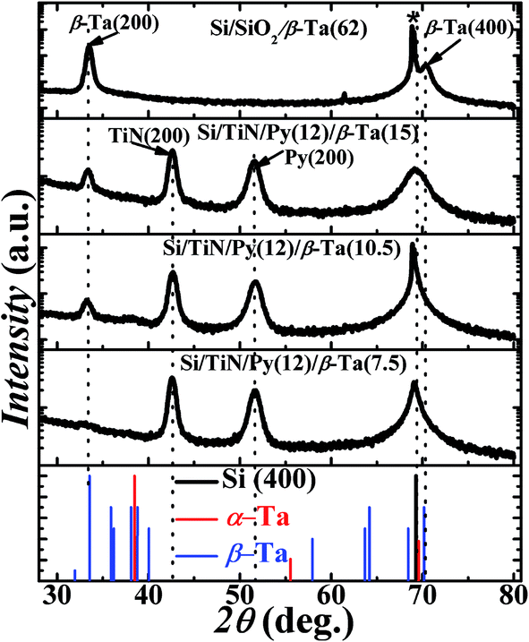
In this study, the effect of change in thickness of β-Ta film (1.5–15 nm) deposited over the optimized Py layer (2-D epi-Py of 12 nm) on spin pumping mechanism is explored. Fig. 4 shows the X-ray diffraction patterns recorded in θ–2θ mode for β-Ta (62 nm), Si/TiN (8 nm)/Py (12 nm)/β-Ta (7.5 nm), Si/TiN (8 nm)/Py (12 nm)/β-Ta (10.5 nm), Si/TiN (8 nm)/Py (12 nm)/β-Ta (15 nm) and compared with the JCPDS (joint committee on powder diffraction standards) files (pdf#191290 & pdf#040788) of Ta shown in bottom panel. The growth of Ta has been done at high power (150 W) to ensure formation of the desired tetragonal β-Ta phase. The observed 2θ peak position at 33.4° corresponds to d value of 2.67 Å, that matches with the reported values.47 It reveals that the Ta thin films have grown in desired tetragonal β-phase oriented preferentially along (200), instead of the body centered cubic α-Ta phase. The (400) peak of β-Ta in all Si/TiN (8 nm)/Py (15 nm)/β-Ta (tTa nm) samples is not clearly distinguishable as it merged with Si(400) due to low thickness of Ta.
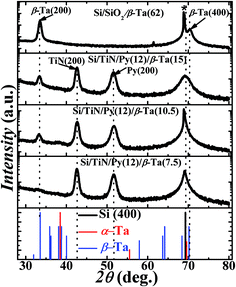 |
| | Fig. 4 Bottom panel shows the standard XRD pattern as per JCPDS file for Ta thin films. The blue lines are the peak locations for β-Ta phase and red lines are for α-Ta phase. Black line corresponds to Si(400). The top panel shows the θ–2θ X-ray diffraction (XRD) pattern of pure Ta thin film grown on Si(100) substrate having native SiO2 layer. In between the top and bottom panels, the other three panels are θ–2θ XRD patterns for Si/TiN/Py/β-Ta (tTa = 7.5, 10.5, 15 nm) bilayers with Py thickness of 12 nm. The peaks from (200) planes belonging to Py and TiN are also indicated. The star symbol highlights the (400) peak from Si substrate. | |
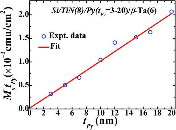
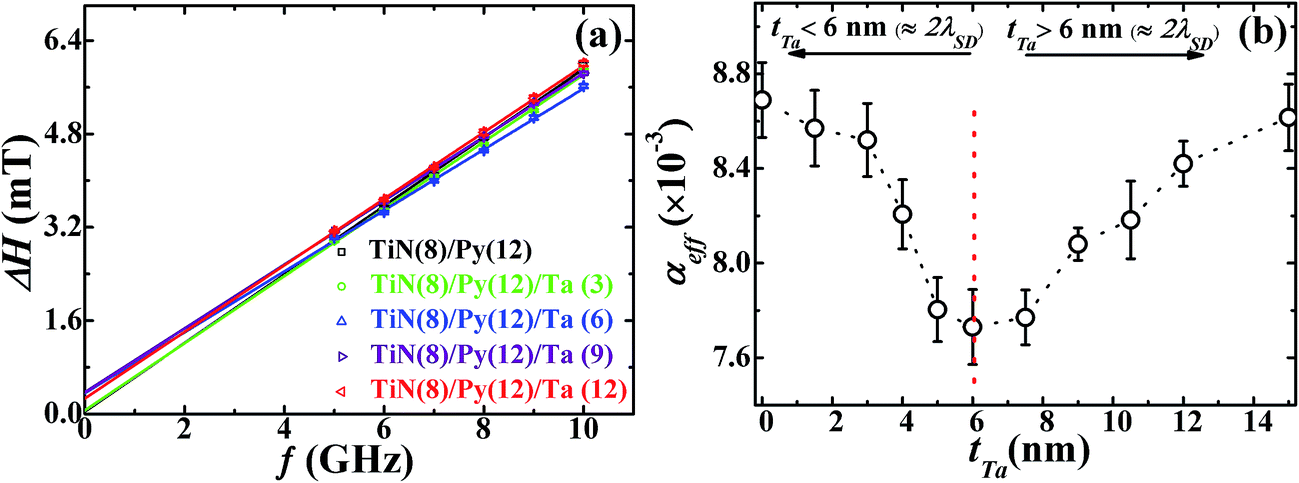
The FMR spectra of TiN (8 nm)/Py (12 nm)/β-Ta (tTa nm) samples are recorded at different constant frequencies in the range 5–10 GHz. For clarity and conciseness, typical representative FMR spectra recorded at 9 GHz frequency for different tTa samples are shown in Fig. 5(a). The various FMR spectra are fitted with derivative of Lorentzian function as shown by solid lines in Fig. 5(a), and the values of fitting parameters Hr and ΔH are determined at different constant frequencies. The frequency dependence of observed Hr for various TiN (8 nm)/Py (12 nm)/β-Ta (tTa nm) samples is shown in Fig. 5(b). The values of Hr are found to be nearly constant irrespective of β-Ta layer thicknesses (i.e. independent of tTa), at all the frequencies as shown in Fig. 5(c). This suggests the negligible presence of extrinsic TMS contribution to the overall damping in these layers. The f vs. Hr data are fitted using the Kittel's eqn (2);  , and fits are shown by solid lines in Fig. 5(b). The estimated values of 4πMeff are nearly constant within experimental error for all different tTa layers (see Fig. ESI5(b)†). However these constant values are slightly higher than 4πMeff value of Py (12 nm) layer. This slight increase in 4πMeff might be result of either the magnetic proximity effect,26,48,49 or the interface modification during the β-Ta layer deposition over Py layer. To explore it further we have plotted the 4πMeff vs. 1/tPy data for Si/TiN (8 nm)/Py (tPy = 3–20 nm) and Si/TiN (8 nm)/Py (tPy = 3–20 nm)/β-Ta(6), respectively in Fig. 5(d). We have observed that there is higher slope when there in the absence of Ta layer. Even the y-axis intercept 4πMs is higher for Si/TiN (8 nm)/Py (tPy = 3–20 nm)/β-Ta(6) as compared to Si/TiN (8 nm)/Py (tPy = 3–20 nm). It clearly confirms that the higher value of 4πMs might be due to the additional magnetization added into it due to addition of β-Ta layer, though β-Ta induced changes in surface anisotropy is also observed which is however expected. However these changes are independent of tTa layers as evident from the constant values of 4πMeff for all different β-Ta layers. We have also studied the possibility of magnetic dead layer formation which can also affect the saturation magnetization in epi-Py/β-Ta interface due to the presence of β-Ta layer adjacent to epi-Py layer as seen by other groups.11 However, such issue is not seen in the present samples. If dead layer is supposed to be formed in epi-Py/β-Ta interface, then there would must be a decrease in magnetization in-terms of emu cm−3 due to over estimation of volume of the epi-Py in epi-Py/β-Ta, which is not supported by the effective magnetization of samples inferred using FMR. To further strengthen the absence of dead layer in our studied samples we have performed the M vs. H measurement on epi-Py (3–20 nm)/β-Ta (6 nm) series of samples. We have plotted the (Ms × tPy) vs. tPy (3–20 nm) and congruently linearly fitted the data as shown Fig. 6, the zero intercept of Ms × tPy vs. tPy (3–20 nm) data evidently affirms the absence of dead-layer formation in these samples.
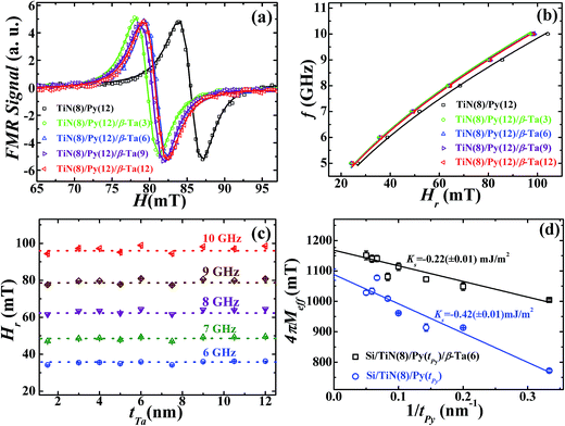 |
| | Fig. 5 (a) The derivative FMR spectra (recorded at 9 GHz) of the different samples of TiN (8 nm)/Py (12 nm)/Ta (tTa) series, where the Ta layer thickness tTa varies from 1.5 to 15 nm. Symbols represent experimental points and solid lines show the fit using eqn (1). (b) The frequency (f) vs. in-plane resonance field (Hr) dependence for samples with different tTa and solid lines shows the fit employing eqn (2). (c) The tTa dependence of Hr i.e. Hr vs. tTa for TiN (8 nm)/Py (12 nm)/Ta (tTa) samples corresponding to different constant resonance frequencies. The f vs. Hr plots for samples with tTa = 1.5, 4, 5, 7.5, and 10.5 nm, refer Fig. 4a of the ESI† file.† (d) 4πMeff vs. 1/tPy plots for Si/TiN (8 nm)/Py (tPy = 3–20 nm) and Si/TiN (8 nm)/Py (tPy = 3–20 nm)/β-Ta(6) multilayer thin films. Open symbols are experimental data and solid lines are fit to experimental data by using expression 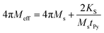 . . | |
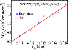 |
| | Fig. 6 Thickness dependent saturation magnetization per unit area (MstPy vs. tPy) plot of epitaxial Si–TiN (8 nm)/Py (tPy)/β-Ta (6 nm). Open symbols are experimental data and solid line is t linear fit. | |
Fig. 7(a) shows the observed frequency dependence of ΔH (open data symbols) and the fitted curves (solid lines) using eqn (5), which shows that ΔH increases linearly with the resonance frequency. The inhomogeneous broadening, ΔH0 ∼ 0.27–0.37 mT, in Py(12)/β-Ta (6, 9, 12 nm) samples are bit higher as compare to the bare Py(12), and this behavior is matching excellently well with those values reported in literatures.26 The difference observed in the ΔH0 in samples with and without β-Ta over layer can be attributed to the finite surface modification of the underlying Py layer as more and more heavy Ta atoms are sputtered over Py. Consistent with the results of Fig. 5(c), the linear increase of ΔH with f clearly suggests that the damping of the precession in this β-Ta capped bilayer system is largely governed by the intrinsic Gilbert's phenomena. Therefore, the contributions in the damping from an extrinsic TMS effects are expected to be very small. The variation of the estimated values of effective Gilbert damping constant αeff (=α + Δα(tTa)) with β-Ta layer thickness is shown in Fig. 7(b). Here α is the damping constant for Si/TiN (8 nm)/Py (12 nm) and Δα(tTa) term comes due to the spin pumping from the adjacent Ta layer in the TiN (8 nm)/Py (12 nm)/β-Ta (tTa nm) bilayers. It is evident that the observed values of αeff(tTa) for these bilayers are smaller than the damping constant found for the bare TiN (8 nm)/Py (12 nm) sample (Fig. 7(b)). This is quite anomalous because the spin pumping in a FM/NM system is usually accompanied with either significant increase in αeff (e.g., when NM = Pt, Pd, etc.)2,3,6,21,23 or negligible increase in αeff (e.g., when NM = Ta, Au, Cu, Al, etc.).2,3,5,6,21,23 In addition to the observed anomalous decrease of αeff(tTa) it also exhibits a minimum near tTa ≈ 6 nm (β-Ta (4 nm) + Ta2O5 (2 nm)) (Fig. 7(b)) which is discussed in forthcoming section.
 |
| | Fig. 7 (a) Variation of ΔH with f i.e. ΔH vs. f at different constant tTa and the solid lines fits using eqn (5). Here the Ta layer thickness tTa varies from 1.5 to 15 nm. (b) The effective Gilbert damping constant (αeff) obtained from the fitting using eqn (5). The dotted lines are guide to the eyes. The ΔH vs. f plots for samples with tTa = 1.5, 4, 5, 7.5, and 10.5 nm, refer Fig. 4(b) of the ESI† file.† | |
We now turn to the different aspects of spin pumping from materials perspective, particularly the choice of NM metal. In the present case of TiN (8 nm)/Py (12 nm)/β-Ta (tTa nm) bilayers, owing to the smaller spin-flip rate compared to the rate of spin-injection from the Py layer, the β-Ta layer can be assumed to act as non-magnetic reservoir.22 Under this condition, when the magnetization ![[m with combining right harpoon above (vector)]](https://www.rsc.org/images/entities/i_char_006d_20d1.gif) precesses around the effective applied magnetic field, a transfer of spin angular momentum(
precesses around the effective applied magnetic field, a transfer of spin angular momentum(![[S with combining right harpoon above (vector)]](https://www.rsc.org/images/entities/i_char_0053_20d1.gif) ) from Py to the Ta layer is expected. This transfer of only takes place if the thickness of the FM layer is greater than its transverse spin coherence length, which is typically <1 nm in case of transition metal elements such as Co, Ni, Fe, etc.22,25 The magnetization precession in the FM layer induces a torque, which governs the current density of spin injection jS from Py to β-Ta layer.21–25,50,51 The spin current density
) from Py to the Ta layer is expected. This transfer of only takes place if the thickness of the FM layer is greater than its transverse spin coherence length, which is typically <1 nm in case of transition metal elements such as Co, Ni, Fe, etc.22,25 The magnetization precession in the FM layer induces a torque, which governs the current density of spin injection jS from Py to β-Ta layer.21–25,50,51 The spin current density  can be written as:
| |
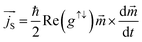 | (7) |
where
is the unit vector along Py layer's magnetization, and Re (
g↑↓) is the real-part of the spin mixing conductance
g↑↓ which governs the transportation efficiency of spin current through the interface. In the present case, the imaginary part of
g↑↓ is expected to be insignificant
51 because of the observed very weak dependence of the resonance field on the β-Ta layer thickness (
Fig. 5(c)) and hence can be neglected. The spin current generated by magnetization-precession (
i.e., spin pumping) is polarized perpendicular both to the instantaneous magnetization
and its time derivative

. It is to be recalled here that this transfer of
from FM to NM layer is known to depend critically upon the nature of the NM layer
via a probability parameter
ε which is related to the change of the spin orientation of the conduction electrons due to the momentum transfer, and is governed by the ratio of spin elastic scattering time to spin flip time,
i.e. 
. The
ε can also be expressed in terms of fine structure constant
αfine and atomic number
ZNM of NM layer,
i.e. ε = (
ZNMαfine)
4. It may be noted that the
ε value, 0.0805 ± 0.0002, for β-Ta
52–54 is smaller compared to
ε value, ≥0.1049, reported for Pt.
53 Tserkovnyak
et al.21,22,24,25 showed that in the case of
ε > 0.1, the spin accumulation at the interface is not possible in sharp contrast to the case when
ε < 0.1.
In the case for NM layer having ε < 0.1, (e.g., β-Ta, as in the present case) and tNM ≤ λSD, the spin angular momentum () associated with the spins accumulated near the Py (12 nm)/β-Ta interface creates a non-equilibrium spin density in β-Ta layer.21,23 However, according to spin pumping model of Tserkovnyak et al.,21 the spin accumulation is expected to be insignificant for non-magnetic metal layer thickness higher than λSD due to the diffusive nature of the spin transport. We would also like to mention here that a substantial mismatch of Fermi surfaces of the FM and NM layers at the interface, which is also the case in the presently studied Py/β-Ta bilayers, can also result in a non-equilibrium spin accumulation, as argued theoretically by Stiles et al.30 As a consequence of a non-equilibrium spin density in β-Ta layer, a back flow of spin current (indicated by  ) into the Py layer takes place. This back flow opposes the spin current entering in to the β-Ta layer. Therefore, in such a case the net spin current
  can be expressed as
  . The back flow spin current is expressed as
 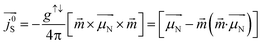 .22 Theoretically, it was proposed that accumulation of spins at the interface of such FM/NM systems is accompanied by absorption of spin angular momentum at the interface.30 It was further established that during this back flow, while the component of
  parallel to the instantaneous magnetization (t) of the FM layer effectively suppresses the spin pumping from FM layer,21–25,50,51 the interaction of the transverse component of
  with the in-plane magnetization of FM layer generates a torque23 which is however not sufficient to reduce the effective Gilbert damping constant (αeff) under total angular momentum conservation. However the physical origin of this observed damping behavior can be understood as a result of net non-equilibrium spin accumulation linked with anti-damping toque on FM layer under total energy conservation. Before looking into this non-equilibrium spin accumulation linked with anti-damping we would like to remark that during FMR, the spin current injected by FM layer into the NM is converted into the charge current by ISHE. The efficiency of this conversion depends on the spin flip probability of the NM material. In case of β-Ta this spin to charge conversation efficiency is low due to its low value of spin flip probability (0.08)52–54 as compared to higher value for Pt (0.10).55 As a result β-Ta accumulates more spins up to λSD compared to Pt which is a spin sink material. However, the small percentage change of spin current into charge current in β-Ta is responsible for a weak source for in-plane charge current. The strength of this in-plane charge current density starts gradually decreasing when tTa exceeds λSD. This significant amount of in-plane charge current is responsible for Rashba spin–orbit torque at interface; due to the structural inversion asymmetry of the two dissimilar materials at the interface of Py/β-Ta, in the presence this in-plane charge current due to ISHE, the spin–orbit Hamiltonian breaks the degeneracy of the electron spin states near the interface, creating a non-equilibrium spin-accumulation, known as Rashba spin–orbit torque.
Therefore a net non-equilibrium spin accumulation results from, (i) Rashba spin–orbit torque at interface (ISOC contribution), (ii) spin pumping induced spin accumulation in β-Ta, up to λSD (BSOC contribution), and (iii) interfacial Fermi surface mismatch. This net non-equilibrium spin accumulation exerts a torque on local magnetization of FM layer. The spin torque is given by11,12  , or more generally the net spin torque is given by, = T⊥Ŝ × + T∥ × Ŝ × , where
  is net non-equilibrium spin density, T⊥ is out of plane torque or field-like torque, T∥ is in-plane torque or anti-damping torque, τΔ characterize the time scale of the precession of the spin density around the magnetization, and Txc is the parameter associated with the momentum relaxation rate
  due to spin-independent scattering, ferromagnetic exchange splitting (Δxc) and spin relaxation time (τsf). The in-plane torque arises from a change of the spin density induced by its precession around the exchange field. However, in presence of spin accumulation (τsf → ∞), anti-damping to field-like torque ratio can be represented as,
  . Here field-like torque strength is negligible since the values of Hr are independent of tTa. Nevertheless the field-like torques usually become relatively strong at lower thickness (<7 nm) of FM layer.56 As the tNM increases upto tTa = 6 nm ≈ (∼2λSD of Ta (∼4 nm) + Ta2O5 (∼2 nm)) the net spins accumulation, interfacial and inside β-Ta, increases which results in escalation of the net spin accumulation induced in-plane torque (anti-damping torque) on FM. Consequently, damping reduces till the 2λSD (+Ta2O5 (∼2 nm)) of β-Ta. However at tTa ≥ 6 nm ≈ (∼2λSD of Ta (∼4 nm) + Ta2O5 (∼2 nm)) the net non-equilibrium spin accumulation starts diminishing because (i) spin coherence within the bulk of Ta dies out,53 and (ii) ISHE signal start diminishing which results an decrease in the Rashba spin–orbit torque at interface. As a result as tNM increases beyond this thickness (∼6 nm) the net spin accumulation induced in-plane torque on FM starts diminishing and leads to the increase in the Gilbert damping as shown in Fig. 7(b). Our results suggest that in Py/β-Ta bilayer system the anti-damping torque dominates, i.e., T∥ ≫ T⊥. Therefore the precession of the spin density is along the exchange field, and the spin momentum relaxation rate is quite low which is however expected in the case of β-Ta due to its low conductivity or the presence of net non-equilibrium spin accumulation.
The observed thickness dependent αeff in the TiN (8 nm)/Py (12 nm)/β-Ta (tTa) bilayers (Fig. 7(b)) can therefore be attributed to net non-equilibrium spin accumulation at the FM/NM interface and in the NM layer. It may however be noted here that Rashba like anti-damping torque exists predominantly in presence of uniform precession of magnetization.13,28–30 As established in the previous section, this is indeed the case with the TiN (8 nm)/Py (12 nm) stack. Therefore, the RSOT arising due to spin absorption occurring at the Py/β-Ta interface along with the BSOC contributions are responsible for reduction in effective Gilbert damping constant αeff from 0.0087 (in tTa = 0) to 0.0077 (in tTa = 6 nm), i.e., a change Δα(tTa) = αeff − α = −0.0010 occurs when tTa increases to 6 nm (≈2λSD). However we can't ignore the fact that reduction in the αeff with an increase in tNM might also be caused by a change of the gyromagnetic ratio, as expected in presence of spin pumping and a backflow, but to confirm it further detailed investigations in term of high frequency in-plane and out-plane FMR measurement are needed.23
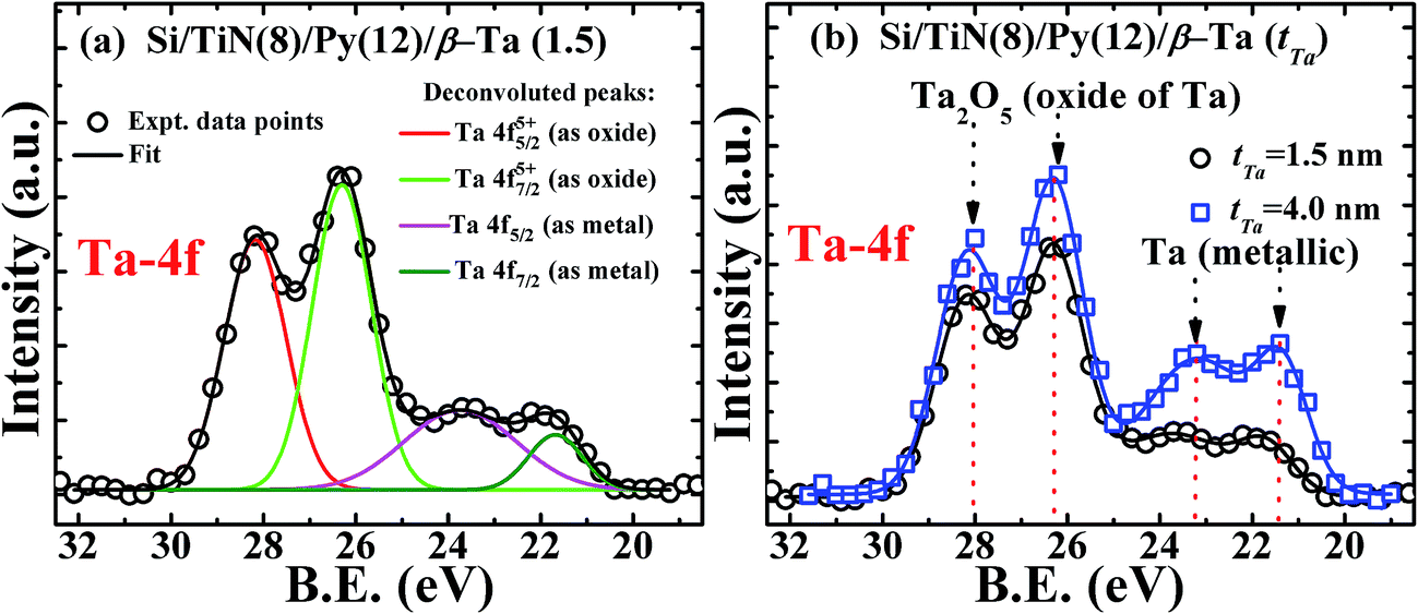
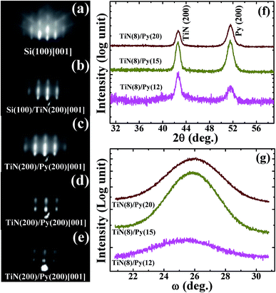
In order to ascertain what constitutes the interface between top Ta layer and the underlying Py layer, we have carried out the X-ray photoelectron spectroscopy (XPS) studies of Ta/Py bilayers of various Ta thicknesses in the range belonging to the anti-damping regime, i.e., tTa < 6 nm regime. Fig. 8 shows the XPS spectra of Ta-4f for two bilayer samples having different Ta layer thicknesses, the lowest 1.5 nm used in our study (that is also about the minimal self-passivating thickness) and a sufficiently larger thickness of tTa = 4 nm (but less than 6 nm). The XPS spectra of the epi-Py (12 nm)/β-Ta (1.5 nm) bilayer shown in Fig. 8(a), on deconvolution reveals Ta-4f5/2 and Ta-4f7/2 binding energy peaks for the oxidized tantalum at 28.16 ± 0.03 eV, 26.30 ± 0.02 eV, metallic tantalum at 23.20 ± 0.12 eV, and 21.32 ± 0.05 eV, respectively. The position of peaks matches with the known peak positions.57 Fig. 8(b) compares the XPS spectra of bilayers with tTa = 1.5 and 4.0 nm. We observe that the oxidized Ta-4f peaks almost remain the same, whereas the metallic Ta-4f peaks are much reduced in intensity in case of bilayer tTa = 1.5 nm, the peak positions remaining same. It may be stressed here that lower peak intensity of the XPS signal due to metallic Ta compared to that due to Ta as oxide in a given specimen should not be directly taken as indication of their absolute thicknesses since in the XPS, which is highly surface sensitive technique, the signal from the surface oxide layer is expected to be far stronger than the protected Ta metal below the top oxide layer. Nevertheless, the relative comparison of the XPS data of Fig. 8 suggests that the passivating layer thickness of Ta2O5 remains just about the same with increasing Ta layer thickness, resulting in an increase in the balance Ta metal layer thickness. If the minimal Ta thickness of ∼1.5 nm oxidizes completely as suggested by the XPS study (and also from our previous XRR studies26) forming Ta2O5 then the Py layer makes direct contact with Ta2O5 (and not with Ta metal). Since Ta2O5 breaks the inversion symmetry, then due to Rashba effect it will show decrease in damping. The observed decrease in α is 0.0001 for 1.5 nm Ta layer (over the bare Py layer). However on increasing the Ta layer thickness to 4 nm (in which case Py layer is in contact with Ta metal), there is further decrease in α by 0.0004. By the time Ta layer thickness reaches 6 nm α has decreased to 0.0077 from 0.0087 for bare Py (i.e. now −Δα = 0.0010). As explained above, this progressive anti-damping behavior observed as tTa is increased beyond 1.5 nm to 6 nm, attributed to Rashba effect in which anti-damping is a consequence of passing a DC-current through FM/NM bilayers that consists of NM layer lacking inversion symmetry. Below tTa = 2 nm, the reduction in damping, compared to that observed in case of bare Py layer, could also be in part due to the absence of possible oxidation of Py layer.26,58
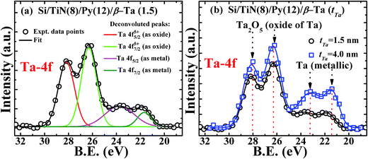 |
| | Fig. 8 (a) The XPS spectra of Ta-4f for epi-Py (12 nm)/Ta (1.5 nm) bilayer showing 4f5/2 and 4f7/2 peaks corresponding to oxidized and metallic tantalum. Lines represent the de-convoluted peaks. (b) Comparison of the XPS spectra of epi-Py (12 nm)/Ta (1.5 nm) bilayer with the epi-Py (12 nm)/Ta (4 nm) bilayer. | |
Above discussion satisfactorily accounts for the observed anomalous decrease in αeff in the present case of Py/β-Ta, we however do not rule out any other plausible physical process accounting for the observed decrease in αeff with the increase in thickness in the tTa < 2λSD regime. The present results therefore suggest the need for further comprehensive modeling of the lower thickness regime of nonmagnetic metal. Having obtained the minimum αeff of 0.0077 in Py (12 nm)/β-Ta (6 nm) bilayers consisting of 2-D Py layer having uniform magnetization precession (minimum TMS) and ∼2λSD thick β-Ta cap layer, we were curious to see what will be the αeff if 3-D Py is used in the bilayers. Therefore we fabricated Py (7 nm)/β-Ta (6 nm) bilayers consisting of 3-D Py layer having significant non-uniform magnetization precession with optimal ∼2λSD thick β-Ta cap layer and found an αeff of 0.0090, which is nearly the same as that for the bare Py layer. Similar situation of high damping constant of bare Py layer and no decrease on adding optimal β-Ta cap layer was also observed for 3 and 5 nm thick 3-D Py layers. This absence of anti-damping behavior in non-uniformly precessing Py layers (tTa < 10 nm) on adding optimal (∼6 nm) β-Ta cap layer is due to diminishing of net non-equilibrium induced anti-damping torque or might be linked to the spin wave induced spin pumping effect.59
Conclusions
We have prepared epitaxial Py layers on TiN buffered Si and have studied the correlation of epi-Py layer thickness with the extrinsic TMS contribution to FMR line-width ΔH and associated Gilbert damping constant α. A non-linear variation of Hr and ΔH with tPy is found for tPy < 12 nm indicating the dominant nature of non-uniform magnetization precession mode responsible for generating the extrinsic TMS. On the other hand, above ≥12 nm of tPy, the Hr and ΔH become constant and independent of Py layer thickness in the studied thickness range of 12–20 nm. This confirms the dominant presence of uniform magnetization precession mode and significant reduction in extrinsic TMS contribution. We have also observed the effect of change in the thickness of the β-Ta layer deposited over the optimized 2-D epitaxial Py (12 nm) layer on the intrinsic spin–orbit contribution in terms of changes in the ΔH and αeff. We found that in the presence of β-Ta layer of thickness less than ∼6 nm, the effect of anti-damping spin–orbit torque acts on the uniform magnetization precession in Py layer and results in anomalous reduction in the ΔH and αeff in comparison to bare Py (12 nm) layer. An attempt has been made to account for the observed effect of change in the β-Ta layer thickness on the anti-damping spin–orbit torque based on the interfacial spin accumulation concept and absorption of spin angular momentum at the FM/NM interface. The tTa ≈ 6 nm (2λSD + 2 nm) is found to be optimum thickness of β-Ta over epitaxial Py film possessing uniform magnetization precession, that is useful for STT device applications owing to maximum transfer of spin current.
Acknowledgements
Useful discussions with Dr P. K. Muduli are thankfully acknowledged. The FIST-DST, Govt. of India is thankfully acknowledged for the XPS measurements at IIT Delhi. One of the contributing authors (N. B.) acknowledges MHRD, Govt. of India for providing Senior Research Fellowship.
References
- C. Chappert and J. V. Kim, Nat. Phys., 2008, 4, 837–838 CrossRef CAS.
- K. Ando, Y. Kajiwara, S. Takahashi, S. Maekawa, K. Takemoto, M. Takatsu and E. Saitoh, Phys. Rev. B: Condens. Matter Mater. Phys., 2008, 78, 014413 CrossRef.
- O. Mosendz, J. E. Pearson, F. Y. Fradin, G. E. W. Bauer, S. D. Bader and A. Hoffmann, Phys. Rev. Lett., 2010, 104, 046601 CrossRef CAS PubMed.
- L. Liu, O. J. Lee, T. J. Gudmundsen, D. C. Ralph and R. A. Buhrman, Phys. Rev. Lett., 2012, 109, 096602 CrossRef PubMed.
- L. Liu, C. F. Pai, Y. Li, H. W. Tseng, D. C. Ralph and R. A. Buhrman, Science, 2012, 336, 555–558 CrossRef CAS PubMed.
- L. Liu, T. Moriyama, D. C. Ralph and R. A. Buhrman, Phys. Rev. Lett., 2011, 106, 036601 CrossRef PubMed.
- J. H. Park, C. H. Kim, H. W. Lee and J. H. Han, Phys. Rev. B: Condens. Matter Mater. Phys., 2013, 87, 041301 CrossRef.
- T. D. Skinner, M. Wang, A. T. Hindmarch, A. W. Rushforth, A. C. Irvine, D. Heiss, H. Kurebayashi and A. J. Ferguson, Appl. Phys. Lett., 2016, 108, 121602 CrossRef.
- A. R. Mellnik, J. S. Lee, A. Richardella, J. L. Grab, P. J. Mintun, M. H. Fischer, A. Vaezi, A. Manchon, E. A. Kim, N. Samarth and D. C. Ralph, Nature, 2014, 511, 449–451 CrossRef CAS PubMed.
- P. M. Haney, H. W. Lee, K. J. Lee, A. Manchon and M. D. Stiles, Phys. Rev. B: Condens. Matter Mater. Phys., 2013, 87, 174411 CrossRef.
- G. Allen, S. Manipatruni, D. E. Nikonov, M. Doczy and I. A. Young, Phys. Rev. B: Condens. Matter Mater. Phys., 2015, 91, 144412 CrossRef.
- X. Wang and A. Manchon, Phys. Rev. Lett., 2012, 108, 117201 CrossRef PubMed.
- A. Manchon and S. Zhang, Phys. Rev. B: Condens. Matter Mater. Phys., 2009, 79, 094422 CrossRef.
- J. C. Slonczewski, J. Magn. Magn. Mater., 1996, 159, L1–L7 CrossRef CAS.
- H. Kurebayashi, J. Sinova, D. Fang, A. C. Irvine, T. D. Skinner, J. Wunderlich, V. Novák, R. P. Campion, B. L. Gallagher, E. K. Vehstedt, L. P. Zârbo, K. Výborný, A. J. Ferguson and T. Jungwirth, Nat. Nanotechnol., 2014, 9, 211–217 CrossRef CAS PubMed.
- K. S. Ryu, L. Thomas, S. H. Yang and S. S. P. Parkin, Nat. Nanotechnol., 2013, 8, 527–533 CrossRef CAS PubMed.
- S. Emori, U. Bauer, S.-M. Ahn, E. Martinez and G. S. D. Beach, Nat. Mater., 2013, 12, 611 CrossRef CAS PubMed.
- V. E. Demidov, S. Urazhdin, H. Ulrichs, V. Tiberkevich, A. Slavin, D. Baither, G. Schmitz and S. O. Demokritov, Nat. Mater., 2012, 11, 1028–1031 CAS.
- J. Kim, J. Sinha, M. Hayashi, M. Yamanouchi, S. Fukami, T. Suzuki, S. Mitani and H. Ohno, Nat. Mater., 2013, 12, 240–245 CrossRef CAS PubMed.
- S. Woo, M. Mann, A. Tan, L. Caretta and G. S. D. Beach, Appl. Phys. Lett., 2014, 105, 202404 CrossRef.
- Y. Tserkovnyak, A. Brataas and G. E. W. Bauer, Phys. Rev. B: Condens. Matter Mater. Phys., 2002, 66, 224403 CrossRef.
- A. Brataas, Y. Tserkovnyak, G. E. W. Bauer and B. I. Halperin, Phys. Rev. B: Condens. Matter Mater. Phys., 2002, 66, 060404(R) CrossRef.
- H. Jiao and G. E. W. Bauer, Phys. Rev. Lett., 2013, 110, 217602 CrossRef PubMed.
- Y. Tserkovnyak, A. Brataas, G. E. W. Bauer and B. I. Halperin, Rev. Mod. Phys., 2005, 77, 1375–1421 CrossRef CAS.
- A. Brataas, Y. Tserkovnyak, G. E. W. Bauer and P. J. Kelly, Spin pumping and spin transfer, published in "Spin Current", ed. S. Maekawa, E. Saitoh, S. Valenzuela and Y. Kimura, Oxford University Press, 2012, ch. 8 Search PubMed.
- N. Behera, S. Chaudhary and D. K. Pandya, Sci. Rep., 2016, 6, 19488 CrossRef CAS PubMed.
- S. Kim, D. J. Kim, M. S. Seo, B. G. Park and S. Y. Park, Appl. Phys. Lett., 2015, 106, 032409 CrossRef.
- I. M. Miron, G. Gaudin, S. Auffret, B. Rodmacq, A. Schuhl, S. Pizzini, J. Vogel and P. Gambardella, Nat. Mater., 2010, 9, 230–234 Search PubMed.
- G. Tatara, N. Nakabayashi and K. J. Lee, Phys. Rev. B: Condens. Matter Mater. Phys., 2003, 87, 054403 CrossRef.
- M. D. Stiles and A. Zangwill, Phys. Rev. B: Condens. Matter Mater. Phys., 2002, 66, 14407 CrossRef.
- M. J. Hurben and C. E. Patton, J. Appl. Phys., 1998, 83, 4344–4365 CrossRef CAS.
- R. Arias and D. Mills, Phys. Rev. B: Condens. Matter Mater. Phys., 1999, 60, 7395–7409 CrossRef CAS.
- B. Heinrich and J. A. C. Bland, Ultrathin Magnetic Structures II: Measurement Techniques and Novel Magnetic Properties, 1994 Search PubMed.
- J. Narayan and B. C. Larson, J. Appl. Phys., 2003, 93, 278–285 CrossRef CAS.
- A. Kumar, D. K. Pandya and S. Chaudhary, Appl. Phys. Lett., 2013, 102, 152406 CrossRef.
- H. An, Y. Kanno, T. Tashiro, Y. Nakamura, J. Shi and K. Ando, Appl. Phys. Lett., 2016, 108, 121602 CrossRef.
- C. Kittel, Phys. Rev., 1948, 73, 155–161 CrossRef CAS.
- J. Okabayashi, J. W. Koo, H. Sukegawa, S. Mitani, Y. Takagi and T. Yokoyama, Appl. Phys. Lett., 2014, 105, 122408 CrossRef.
- H. Lee, L. Wen, M. Pathak, P. Janssen, P. LeClair, C. Alexander, C. K. A. Mewes and T. Mewes, J. Phys. D: Appl. Phys., 2008, 41, 215001 CrossRef.
- A. Azevedo, A. B. Oliveira, F. M. De Aguiar and S. M. Rezende, Phys. Rev. B: Condens. Matter Mater. Phys., 2000, 62, 5331–5333 CrossRef CAS.
- Z. O. Lei, G. J. Li, W. F. Egelhoff, P. T. Lai and P. W. T. Pong, IEEE Trans. Magn., 2011, 47, 602 CrossRef CAS.
- Z. O. Lei, G. J. Li, W. F. Egelhoff, P. T. Lai and P. W. T. Pong, IEEE Trans. Magn., 2011, 47, 714 CrossRef CAS.
- G. Li, C. W. Leung, C. Shueh, H. F. Hsu, H. R. Huang, K. W. Lin, P. T. Lai and P. W. Pong, Surf. Coat. Technol., 2013, 228, S437–S441 CrossRef CAS.
- G. Woltersdorf, “Spin-pumping and two-magnon scattering in magnetic multilayers”, Ph.D. dissertation, Simon Fraser University, 2004, p. 22.
- W. Alayo, S. Landi Jr, F. Pelegrini and E. Baggio-Saitovitch, J. Magn. Magn. Mater., 2014, 350, 100–106 CrossRef CAS.
- R. C. Oliveira, R. L. Rodriguez-Suárez, F. M. deAguiar, S. M. Rezende, J. R. Fermin and A. Azevedo, J. Magn. Magn. Mater., 2004, 272, e795–e796 CrossRef.
- M. H. Read and C. Altman, Appl. Phys. Lett., 1965, 7, 51–52 CrossRef CAS.
- Y. Sun, H. Chang, M. Kabatek, Y. Y. Song, Z. Wang, M. Jantz, W. Schneider, M. Wu, E. Montoya, B. Kardasz, B. Heinrich, S. G. E. T. Velthuis, H. Schultheiss and A. Hoffmann, Phys. Rev. Lett., 2013, 111, 106601 CrossRef PubMed.
- Y. Yang, Y. Wu, B. Wu, K. Yao, S. Shannigrahi and B. Zong, J. Appl. Phys., 2014, 115, 17C509 CrossRef.
- G. Woltersdorf, O. Mosendz, B. Heinrich and C. H. Back, Phys. Rev. Lett., 2007, 99, 227207 CrossRef PubMed.
- A. Brataas, Y. V. Nazarov and G. E. W. Bauer, Phys. Rev. Lett., 2000, 84, 2481–2484 CrossRef CAS PubMed.
- A. A. Abrikosov and L. P. Gor’kov, Sov. Phys., 1962, 15, 752–757 Search PubMed.
- R. Meservey and P. M. Tedrow, Phys. Rev. Lett., 1978, 41, 805–808 CrossRef CAS.
- Q. Yang, P. Holody, S. F. Lee, L. L. Henry, R. Loloee, P. A. Schroeder, W. P. Pratt and J. Bass, Phys. Rev. Lett., 1994, 72, 3274–3277 CrossRef CAS PubMed.
- H. Nakayama, K. Ando, K. Harii, T. Yoshino, R. Takahashi, Y. Kajiwara, K. Uchida, Y. Fujikawa and E. Saitoh, Phys. Rev. B: Condens. Matter Mater. Phys., 2012, 85, 144408 CrossRef.
- X. Fan, H. Celik, J. Wu, C. Ni, K. J. Lee, V. O. Lorenz and J. Q. Xiao, Nat. Commun., 2014, 5, 3042 Search PubMed.
- H. Zhao, G. Yu and H. Si, J. Mater. Sci. Technol., 2004, 20, 239–240 CAS.
- A. Ruiz-Calaforra, T. Brächer, V. Lauer, P. Pirro, B. Heinz, M. Geilen, A. V. Chumak, A. Conca, B. Leven and B. Hillebrands, J. Appl. Phys., 2015, 117, 163901 CrossRef.
- J. H. Kwon, J. Yoon, M. Hayashi, P. Deorani, H. Yang, J. M. Lee, J. Sinha and K. J. Lee, Sci. Adv., 2016, 2, e1501892 Search PubMed.
Footnote |
| † Electronic supplementary information (ESI) available. See DOI: 10.1039/c6ra25980d |
|
| This journal is © The Royal Society of Chemistry 2017 |
Click here to see how this site uses Cookies. View our privacy policy here. 
 Open Access Article
 This Open Access Article is licensed under a Creative Commons Attribution-Non Commercial 3.0 Unported Licence
 a,
Ankit Kumarab,
Sujeet Chaudhary*a and
Dinesh K. Pandya
a,
Ankit Kumarab,
Sujeet Chaudhary*a and
Dinesh K. Pandya

 which is induced by the surface and interfacial defects and also by the anisotropic orbital angular momentum,38 4πMs is the saturation magnetization of Py layer, and KS is the surface anisotropy energy constant. The value of 4πMs, as determined from the fitting of 4πMeff vs. tPy data using the expression
 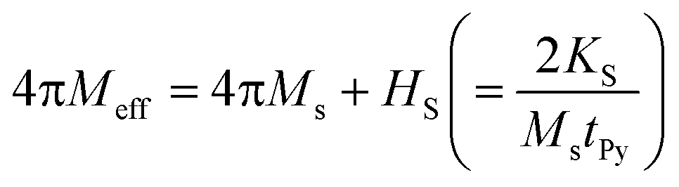 , is found to be 1088 (±19) mT (see Fig. ESI5(a)†). The 4πMs value obtained from FMR measurements is consistent with the value of 1195 (±100) mT obtained from VSM measurements.39 Here it is to be noted that one can't directly extract the HS from the effective magnetization because HS is also affected by shift in the Hr with respect to tPy.40 Fig. 3(a) shows the variation of Hr with f for different Py(tPy) films, and this observed variation is fitted to eqn (2). The fitted values of 4πMeff are found to vary from 772 mT to 1028 mT as Py thickness increases from 3 to 20 nm (see Fig. ESI5a†). Fig. 3(b) shows a shift in the resonance field Hr on increasing tPy corresponding to different constant resonance frequencies. This shift can be linked with the nature of resonance mode associated with the samples. To explain this tPy dependence of Hr, we utilized the following expression,37
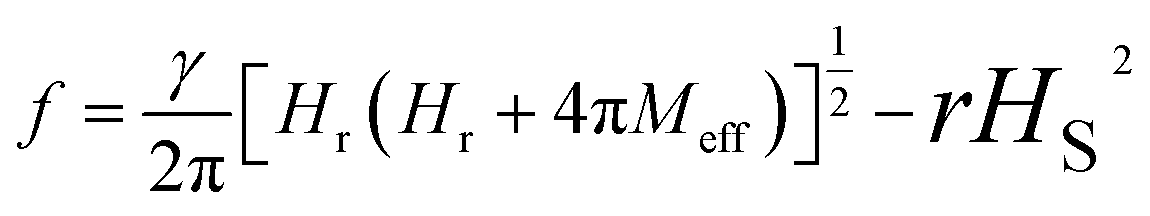

 ) is also associated with the magnetization relaxation process, and therefore ΔH also depends upon the nature of resonance precession mode. Thus the increase in ΔH for tPy < 12 nm is also related to the finite contributions from the TMS. We shall now quantitatively separate the contributions to the overall damping constant “α” coming from intrinsic (i.e., the Gilbert's damping due to magnon-electron scattering) mechanism and the extrinsic TMS mechanism. These two contributions will be indicated by αint. and αext., respectively. First, we fit the experimental ΔH(f) data for different tPy (Fig. 3(e)) using the standard eqn44
 , and fits are shown by solid lines in Fig. 5(b). The estimated values of 4πMeff are nearly constant within experimental error for all different tTa layers (see Fig. ESI5(b)†). However these constant values are slightly higher than 4πMeff value of Py (12 nm) layer. This slight increase in 4πMeff might be result of either the magnetic proximity effect,26,48,49 or the interface modification during the β-Ta layer deposition over Py layer. To explore it further we have plotted the 4πMeff vs. 1/tPy data for Si/TiN (8 nm)/Py (tPy = 3–20 nm) and Si/TiN (8 nm)/Py (tPy = 3–20 nm)/β-Ta(6), respectively in Fig. 5(d). We have observed that there is higher slope when there in the absence of Ta layer. Even the y-axis intercept 4πMs is higher for Si/TiN (8 nm)/Py (tPy = 3–20 nm)/β-Ta(6) as compared to Si/TiN (8 nm)/Py (tPy = 3–20 nm). It clearly confirms that the higher value of 4πMs might be due to the additional magnetization added into it due to addition of β-Ta layer, though β-Ta induced changes in surface anisotropy is also observed which is however expected. However these changes are independent of tTa layers as evident from the constant values of 4πMeff for all different β-Ta layers. We have also studied the possibility of magnetic dead layer formation which can also affect the saturation magnetization in epi-Py/β-Ta interface due to the presence of β-Ta layer adjacent to epi-Py layer as seen by other groups.11 However, such issue is not seen in the present samples. If dead layer is supposed to be formed in epi-Py/β-Ta interface, then there would must be a decrease in magnetization in-terms of emu cm−3 due to over estimation of volume of the epi-Py in epi-Py/β-Ta, which is not supported by the effective magnetization of samples inferred using FMR. To further strengthen the absence of dead layer in our studied samples we have performed the M vs. H measurement on epi-Py (3–20 nm)/β-Ta (6 nm) series of samples. We have plotted the (Ms × tPy) vs. tPy (3–20 nm) and congruently linearly fitted the data as shown Fig. 6, the zero intercept of Ms × tPy vs. tPy (3–20 nm) data evidently affirms the absence of dead-layer formation in these samples.
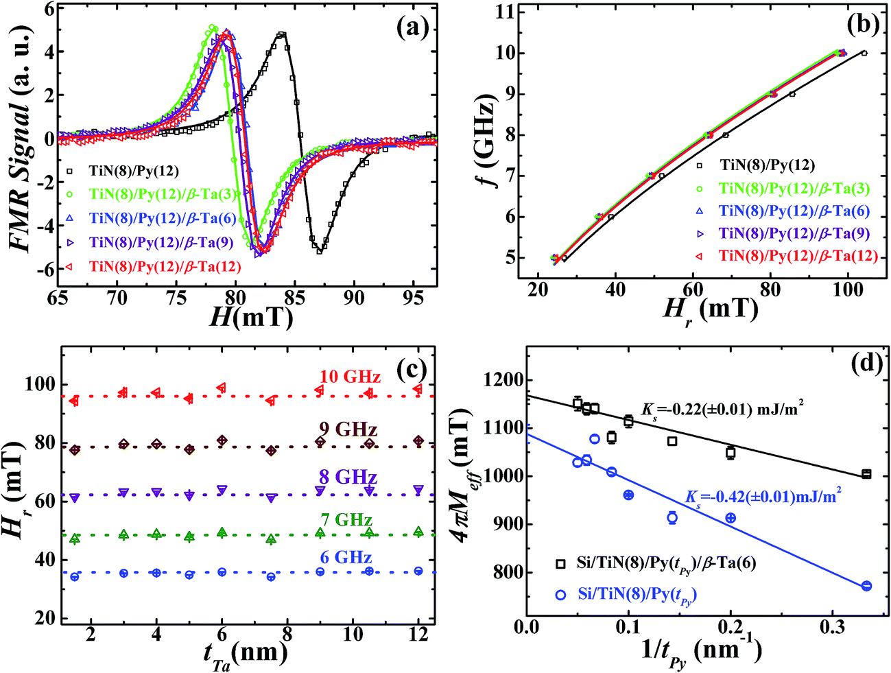
 .
.
 can be written as:
 . It is to be recalled here that this transfer of
 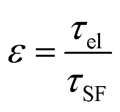 . The ε can also be expressed in terms of fine structure constant αfine and atomic number ZNM of NM layer, i.e. ε = (ZNMαfine)4. It may be noted that the ε value, 0.0805 ± 0.0002, for β-Ta52–54 is smaller compared to ε value, ≥0.1049, reported for Pt.53 Tserkovnyak et al.21,22,24,25 showed that in the case of ε > 0.1, the spin accumulation at the interface is not possible in sharp contrast to the case when ε < 0.1.
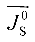 ) into the Py layer takes place. This back flow opposes the spin current entering in to the β-Ta layer. Therefore, in such a case the net spin current
 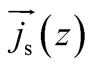 can be expressed as
 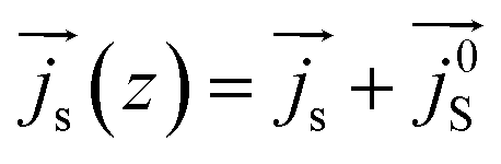 . The back flow spin current is expressed as
 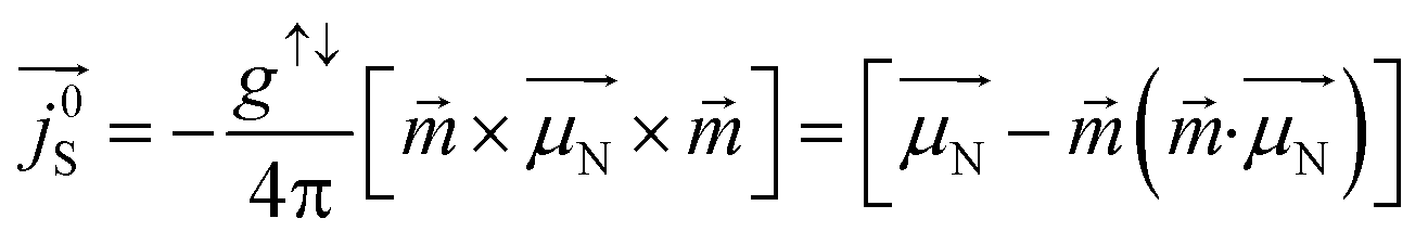 .22 Theoretically, it was proposed that accumulation of spins at the interface of such FM/NM systems is accompanied by absorption of spin angular momentum at the interface.30 It was further established that during this back flow, while the component of
  parallel to the instantaneous magnetization
  with the in-plane magnetization of FM layer generates a torque23 which is however not sufficient to reduce the effective Gilbert damping constant (αeff) under total angular momentum conservation. However the physical origin of this observed damping behavior can be understood as a result of net non-equilibrium spin accumulation linked with anti-damping toque on FM layer under total energy conservation. Before looking into this non-equilibrium spin accumulation linked with anti-damping we would like to remark that during FMR, the spin current injected by FM layer into the NM is converted into the charge current by ISHE. The efficiency of this conversion depends on the spin flip probability of the NM material. In case of β-Ta this spin to charge conversation efficiency is low due to its low value of spin flip probability (0.08)52–54 as compared to higher value for Pt (0.10).55 As a result β-Ta accumulates more spins up to λSD compared to Pt which is a spin sink material. However, the small percentage change of spin current into charge current in β-Ta is responsible for a weak source for in-plane charge current. The strength of this in-plane charge current density starts gradually decreasing when tTa exceeds λSD. This significant amount of in-plane charge current is responsible for Rashba spin–orbit torque at interface; due to the structural inversion asymmetry of the two dissimilar materials at the interface of Py/β-Ta, in the presence this in-plane charge current due to ISHE, the spin–orbit Hamiltonian breaks the degeneracy of the electron spin states near the interface, creating a non-equilibrium spin-accumulation, known as Rashba spin–orbit torque.
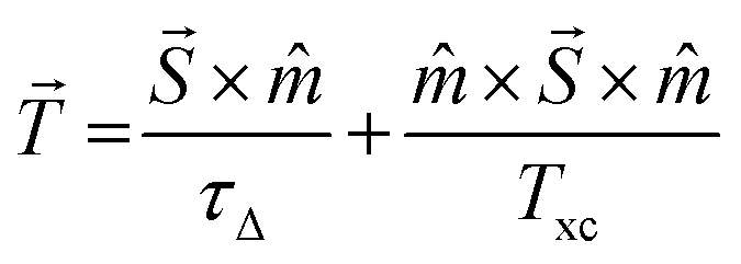 , or more generally the net spin torque is given by,
  is net non-equilibrium spin density, T⊥ is out of plane torque or field-like torque, T∥ is in-plane torque or anti-damping torque, τΔ characterize the time scale of the precession of the spin density around the magnetization, and Txc is the parameter associated with the momentum relaxation rate
  due to spin-independent scattering, ferromagnetic exchange splitting (Δxc) and spin relaxation time (τsf). The in-plane torque arises from a change of the spin density induced by its precession around the exchange field. However, in presence of spin accumulation (τsf → ∞), anti-damping to field-like torque ratio can be represented as,
 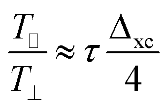 . Here field-like torque strength is negligible since the values of Hr are independent of tTa. Nevertheless the field-like torques usually become relatively strong at lower thickness (<7 nm) of FM layer.56 As the tNM increases upto tTa = 6 nm ≈ (∼2λSD of Ta (∼4 nm) + Ta2O5 (∼2 nm)) the net spins accumulation, interfacial and inside β-Ta, increases which results in escalation of the net spin accumulation induced in-plane torque (anti-damping torque) on FM. Consequently, damping reduces till the 2λSD (+Ta2O5 (∼2 nm)) of β-Ta. However at tTa ≥ 6 nm ≈ (∼2λSD of Ta (∼4 nm) + Ta2O5 (∼2 nm)) the net non-equilibrium spin accumulation starts diminishing because (i) spin coherence within the bulk of Ta dies out,53 and (ii) ISHE signal start diminishing which results an decrease in the Rashba spin–orbit torque at interface. As a result as tNM increases beyond this thickness (∼6 nm) the net spin accumulation induced in-plane torque on FM starts diminishing and leads to the increase in the Gilbert damping as shown in Fig. 7(b). Our results suggest that in Py/β-Ta bilayer system the anti-damping torque dominates, i.e., T∥ ≫ T⊥. Therefore the precession of the spin density is along the exchange field, and the spin momentum relaxation rate is quite low which is however expected in the case of β-Ta due to its low conductivity or the presence of net non-equilibrium spin accumulation.