 Open Access Article
Creative Commons Attribution 3.0 Unported Licence
Facile preparation of polyimide/graphene nanocomposites via an in situ polymerization approach
Songlv Qinab,
Cheng Chena,
Mingjun Cuia,
Afang Zhangb,
Haichao Zhao*a and
Liping Wang*a
aKey Laboratory of Marine Materials and Related Technologies, Zhejiang Key Laboratory of Marine Materials and Protective Technologies, Ningbo Institute of Materials Technology and Engineering, Chinese Academy of Sciences, Ningbo 315201, P. R. China. E-mail: zhaohaichao@nimte.ac.cn; wangliping@nimte.ac.cn
bSchool of Materials Science and Engineering, Shanghai University, Shanghai 200444, China
First published on 13th January 2017
Abstract
In this study, to achieve a compatible and good dispersion of graphene in polyimide matrix, we synthesized an aromatic diamine, aniline trimer, as a polymerizable graphene dispersant. Polyimide/graphene nanocomposites with 0.25–2% mass fraction of graphene were prepared by in situ condensation of pyromellitic dianhydride, 4,4′-oxydianiline, and aniline trimer (AT) functionalized graphene in DMAc, following subsequent thermal imidization at elevated temperatures. UV-vis and Raman spectroscopy verified the π–π interactions between AT and graphene. The microstructure analysis using XRD, SEM, and TEM were performed to investigate the morphology of graphene in the polyimide matrix. The thermal, mechanical, and tribological properties of polyimide/graphene nanocomposites were investigated by TGA, DMA, and friction and wear tests. In view of the ease of preparation and their superior physical properties over neat polyimide, PI/G composites prepared in this study showed promising applications as wear-resistant and self-lubricating materials.
1. Introduction
Owing to their strong mechanical properties, high thermal stability, and low dielectric constants, aromatic polyimides (PIs) make attractive materials for many applications, including microelectronics, aerospace engineering, adhesives, and fuel cells.1–3 However, pure PI resin suffers from some limitations during its application. For instance, a high friction coefficient and poor resistance to mechanical wear limit its wider application as an insulation material for wire and cable applications.4 Moreover, the surface of PIs would accumulate charge when exposed to irradiation by high energy rays, such as oxygen atoms and gamma rays.5 During the last decade, incorporation of nanomaterials in the polymer matrices has become quite a promising technique for the enhancement of physical properties of the corresponding nanocomposites.6 Especially, it is of current great interest to incorporate graphene (G)-base two-dimensional nanofillers into the PI matrix to improve the mechanical, thermal, tribological, and electrical properties of the PI.7Graphene, a single layer of carbon atoms bonded in a repeating pattern of hexagons, exhibits many extraordinary properties.8 However, pristine graphene sheets tend to form agglomerates in a polymer matrix owing to the π–π stacking and van der Waals interactions, which seriously deteriorates the performance of the formed polymer nanocomposites. To explore the unique properties of graphene in polymer nanocomposites, several approaches have been proposed to reduce the aggregation and achieve a good dispersion in the PI matrix, including chemical functionalization, aid of surfactants, and π–π interactions by aromatics. Among these strategies, graphene oxide (GO) has been fully investigated to improve the processability and functionality of graphene. GO carries carboxylate, hydroxyl, and epoxy groups to enable the suspension of GO sheets in polar solvents, making it possible for in situ preparation of graphene-based PI nanocomposites. For instance, Liu et al. successfully prepared PI/GO composite films with improved mechanical and thermal properties by in situ polymerization of pyromellitic dianhydride and 4,4′-oxydianiline with 0.5–2 wt% of silane-functionalized GO. The silane coupling agent improves the dispersion of GO in the PI matrix and facilitates the formation of strong interactions with the PI.9 Ma and coworkers reported a study on the synthesis of NH2-functionalized GO for promoting the dispersion and formation of strong chemical links within the PI matrix. The prepared PI nanocomposites exhibited an ultra-high mechanical strength with a very low dielectric constant.10 Chen et al. demonstrated the preparation of PI/G nanocomposite films by in situ reduction and imidization of the GO/poly(amic acid) composites. The highly aligned functionalized graphene nanosheets in the PI matrix significantly improved the tensile strength and modulus of the nanocomposite.11
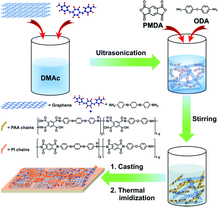
Noncovalent functionalization of graphene by using aromatic molecules is advantageous over a chemical modification method because it does not deteriorate the structure of graphene.12 It has been reported that polyaniline and its oligomers exhibited a special capacity for the dispersion of carbonaceous materials, such as carbon nanotubes and graphene, in various solvents or in a polymer matrix.13,14 Herein, to achieve a homogenous dispersion and compatible graphene/PI interfaces, we demonstrated the preparation of PI/G nanocomposite by using amine-capped aniline trimer (AT) as the graphene dispersant and reactive component for PI, as shown in Fig. 1. First, pristine graphene was exfoliated into nanosheets in dimethylacetamide (DMAc) with a few atomic layers in thickness in the presence of AT. Second, poly(amic acid) (PAA)/graphene suspension was prepared by in situ polymerization of pyromellitic dianhydride (PMDA), 4,4′-oxydianiline (ODA), and various amounts of AT-functionalized graphene (G) nanosheets under a N2 atmosphere at room temperature. Third, polyimide/G nanocomposites were obtained by thermal imidization of PAA/graphene hybrid at an elevated temperature.15 The dispersity of graphene and PAA/graphene hybrid in DMAc was analyzed, and the morphology of graphene in the PI matrix was also investigated by XRD, SEM, and TEM. Further, the thermal, mechanical, and tribological properties of PI/G nanocomposite as a function of graphene content were studied in detail.
2. Experimental section
2.1 Materials
Ammonium persulfate, p-phenylenediamine sulfate, ammonia solution, 4,4′-oxydianiline (ODA), pyromellitic dianhydride (PMDA), and dimethylacetamide (DMAc) were purchased from Aladdin Industrial Corporation. Aniline and HCl solution were supplied from Sinopharm chemical Reagent Co. Ltd. Graphene (G) was provided from Ningbo Morsh Tech Co. Ltd. Aniline trimer (AT) was synthesized according to the reported procedure.162.2 Preparation of AT/graphene suspension in DMAc
The typical procedure for the preparation of AT stabilized G suspensions is as follows: a given amount of AT (0.04 g) was dissolved in DMAc (10 mL) with sonication for 10 min to obtain a homogeneous dark blue solution; a pre-calculated quantity of graphene (0.04 g) was then added to the solution and ultrasonicated for 1 h to obtain the AT-stabilized G suspension.2.3 In situ preparation of PAA/graphene suspension with various mass fractions of graphene
To prepare PAA/graphene composite suspension with various G loadings (0.25 wt%, 0.5 wt%, 1 wt%, and 2 wt%), various quantities of graphene (0.01 g, 0.02 g, 0.04 g, and 0.08 g) were individually added to 28 mL of dry DMAc, and then AT (equivalent to graphene) was added and sonicated for 1 h to obtain the dispersed G suspension. To each abovementioned G suspension, 2.00 g of ODA (0.01 mol) and 2.18 g of PMDA (0.01 mol) were gradually added, and the mixture was vigorously stirred at room temperature for 24 h under a flow of nitrogen, yielding PAA/graphene hybrid suspension. Pure PAA in DMAc solution was prepared by a similar procedure but without the addition of graphene and AT.2.4 Preparation of polyimide/graphene composite films by thermal imidization
PI/G composite films and neat PI were prepared by a solution casting and subsequent thermal imidization method. The prepared PAA/graphene suspension or neat PAA solution were casted on glass and 2 cm × 2 cm sheet steel (316 L) substrates and were subsequently put into a vacuum for degassing for 10 minutes before the imidizing condensation. For thermal imidization reactions, the abovementioned specimens were put into an air circulation oven and heated at 150, 200, 250, and 300 °C for 1 h to evaporate all volatiles and reach thermal imidization. The thickness of the G/PI nanocomposite films is ca. 0.1 mm.2.5 Instruments and characterization
Ultra-violet-visible (UV-vis) spectra of AT and AT/graphene in DMAc were obtained by a UV-vis spectrometer (Lambda 950). The UV-vis spectrum was obtained between 300 and 800 nm. The specimens of graphene sheets, AT, and AT/graphene were observed by a confocal micro Raman spectrometer (Renishaw invia Reflex). Atomic force micrographs (AFM) were obtained using a commercial instrument (Dimension 3100) in the tapping mode. X-ray diffraction (XRD) patterns were acquired by a D8 ADVANCE using Cu-Kα radiation (λ = 0.154 nm) at an accelerating voltage of 40 kV and current of 40 mA. The wear track of graphene/polyimide nancomposite coatings was observed by scanning electron microscopy (SEM1, FEIQuanta FEG250). In addition, the morphology of graphene/polyimide fracture films was observed by scanning electron microscopy (SEM2, HITACHI S4800). To prove that the graphene sheets have already soaked into the graphene/polyimide nanocomposite films, a transmission electron microscope (TEM, JEOL JEM2100) was used. Thermogravimetric analyses (TGA) were carried out using Diamond TG/DTA under air flow at a heating rate of 10° per min.Dynamic mechanical analyses (DMA) were performed using a SDTA861e analyzer. The tribological tests of G/PI nanocomposites under dry sliding condition were conducted on a multi-functional high temperature friction tester (UMT-3, America) at 2 Hz sliding frequency under a constant load of 3 N. Vickers hardness of the PI/G composites was tested on a microhardness tester (HV-1000) under a load of 100 N.
Tribological properties were evaluated using a UMT-3. Evaluation of the tribological behavior was conducted at 2 Hz sliding frequency under a constant load of 3 N and test duration of 30 min. The diameter of the steel ball was 3 mm. The friction mode is reciprocating friction.17 We stick the film on the sheet steel slide to test the friction properties. Before each test, steel balls were cleaned with acetone followed by drying. All the tests were carried out at about 24 °C and a relative humidity of 40–50%. The wear rate and depths of the specimens after tribological testing were measured using a surface profiler (D-100, KLA, Tencor).
3. Results and discussion
3.1 In situ preparation and characterization of the poly(amic acid)/graphene hybrid suspension
Owing to its high aspect ratio and strong interlayer van der Waals interactions, graphene tends to aggregate in the polymer matrix.18 It is, therefore, a challenge to steadily disperse graphene in the polymer matrix for achieving optimal properties. As shown in Fig. 2a, pristine graphene had poor dispersibility and precipitated in DMAc due to agglomeration. Surprisingly, it was found that graphene sheets can be stably dispersed in DMAc solvent by using AT as dispersant (Fig. 2b), making it possible to prepare homogenous poly(amic acid)/graphene suspension via an in situ polymerization approach (Fig. 2c). The dispersion capacity of graphene was up to 5 mg mL−1.19 The driving force for exfoliation of graphene nanosheets is assumed to be noncovalent π–π interactions between aromatic AT molecules and graphene, which can be verified by UV-vis and Raman spectroscopy.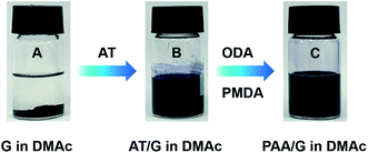 | ||
| Fig. 2 Digital images of (a) graphene in DMAc; (b) aniline trimer/graphene in DMAc; (c) poly(amic acid)/graphene in DMAc. | ||
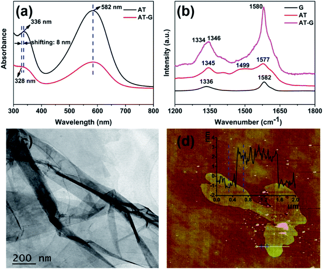
Fig. 3a shows the UV-vis spectroscopy of AT and AT/graphene in DMAc. AT exhibited two characteristic peaks at ca. 336 and 582 nm, which are associated with the benzenoid and quinoid absorption peaks, respectively. Similarly, the AT/graphene suspension also exhibited two absorption peaks, whereas the peak for the π–π* transition of benzenoid was blue-shifted from 336 nm (AT) to 328 nm (AT/graphene), which indicates the π–π interaction between the AT molecules and graphene. For the Raman spectra of G, AT, and AT/graphene shown in Fig. 3b, graphene exhibits a typical G band at 1582 cm−1 and a D band at 1336 cm−1. On the other hand, AT exhibited C–N stretching at ca. 1346 cm−1, phenazine absorptions at 1499 cm−1, and C![[double bond, length as m-dash]](https://www.rsc.org/images/entities/char_e001.gif) C stretching of the quinonoid ring at 1577 cm−1. It is apparent that G bands of graphene shifted to 1580 cm−1 and D bands shifted to 1334 cm−1 for the AT/graphene hybrid, indicating charge transfer interactions between graphene and AT.
C stretching of the quinonoid ring at 1577 cm−1. It is apparent that G bands of graphene shifted to 1580 cm−1 and D bands shifted to 1334 cm−1 for the AT/graphene hybrid, indicating charge transfer interactions between graphene and AT.
The TEM and AFM were applied to characterize the morphology of graphene as shown in Fig. 3c and d. As shown in Fig. 3c, the typical TEM image demonstrates graphene has a nanosheet morphology with corrugated structures. A representative AFM image (Fig. 3d) revealed that the exfoliated graphene nanosheet had a height of ca. 3.2 nm and length in micrometers, which indicated that the aggregated AT/graphene sheets were exfoliated to ultra-thin lamellae of thickness about 10 atom layers.
3.2 Preparation and characterization of PI/G nanocomposites
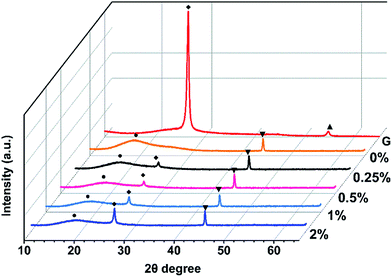
Pure PI and PI/G composites with various mass fractions of graphene loading were prepared by thermal imidization of PAA and PAA/graphene hybrid at elevated temperatures. The XRD spectrum was used to investigate the microstructure of PI/G composite, as shown in Fig. 4. Pristine graphene showed a strong and sharp peak centered at 2θ = 26.5°, which corresponded to the interlayer d-spacing of ca. 0.34 nm. The XRD pattern of neat PI revealed a broad diffraction peak at a 2θ = 18.9°, implying an amorphous structure of PI. After addition of the graphene sheets, polyimide/graphene nanocomposites also exhibited a sharp peak at 2θ = 26.5° and a broad peak at ca. 18.9°. This proved that graphene nanosheets had already been dispersed into the polyimide matrix, even though still existing in crystalline form with several stacked layers. On the other hand, the amorphous state of polyimides was not affected by the incorporation of graphene sheets.20AFM (Fig. 5) was used to investigate the surface morphologies of neat PI and PI/G nanocomposites. The surface roughness (Ra) of neat PI is 4.61 nm and the surface roughness of polyimide/graphene nanocomposites ranged from 4.67 to 7.90 nm. Since the mass fraction of graphene was 0.25%, its surface roughness was similar to that of the neat PI. With an increase in the G content up to 2%, the surface morphologies showed the highest surface roughness of about 7.90 nm.
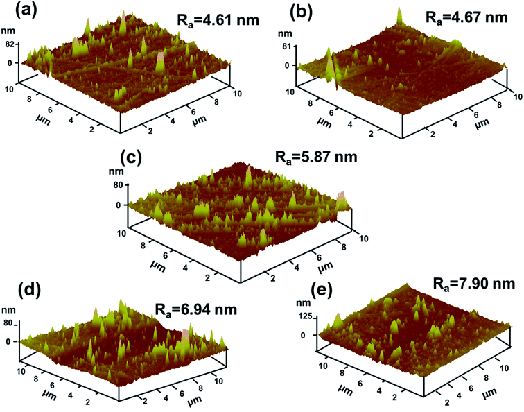 | ||
| Fig. 5 AFM surface morphologies of (a) neat PI, (b) 0.25% G/PI, (c) 0.5% G/PI, (d) 1% G/PI, and (e) 2% G/PI. | ||
Fig. 6a–e show the SEM images of the fractured surfaces of the neat PI and PI/G composite films. The fractured surface of neat PI was relatively smooth and flat, whereas that of the PI/G composite films showed a relatively rough and wrinkled morphology. The much deformed morphology of PI/G composites revealed about the strong interactions and good compatibility between graphene and the PI matrix. Moreover, it can be observed that the planar orientation of graphene in the PI matrix led to layered fractures under an external force.21 Direct observation of the dispersion of graphene in the polyimide matrix could be obtained by TEM (Fig. 6f). It was clearly seen that the graphene sheets were in a randomly dispersed state in the polymer matrix at the 1% graphene loading because AT acted as a protective layer to prevent migration and aggregation of the graphene sheets during the preparation of PI/G nanocomposites.
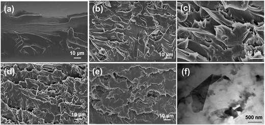 | ||
| Fig. 6 SEM images of (a) neat PI, (b) 0.25% G/PI, (c) 0.5% G/PI, (d) 1% G/PI, (e) 2% G/PI, and (f) TEM image of 1% G/PI. | ||
3.3 Mechanical properties of PI/G composite films
DMA experiments were performed to investigate the reinforcement effect of graphene on the polyimide nanocomposites. Fig. 7a shows the effects of graphene mass fraction on the dynamic storage modulus, E′, of polyimide. The E′ values of all the specimens were temperature dependent and gradually decreased with an increase in temperature. It is evident that the E′ value of polyimide/graphene nanocomposites is much higher than that of the neat polyimide. The E′ of neat PI at ambient temperature is 1480 MPa, whereas all the polyimide/graphene nanocomposites exhibited E′ values over 2100 MPa. The compiled DMA curves of loss modulus (E′′) versus temperature of neat PI and PI/G nanocomposites are displayed in Fig. 7b. The E′′ displays a trend similar to that of E′, showing improvements by the addition of graphene into the PI matrix. It can be concluded that significant increase in the storage and loss modulus values for PI occurs with the incorporation of a small amount of graphene nanofiller. This significant enhancement is indicative of the uniform dispersion of graphene nanosheets in the polyimide resin. Thus, the graphene nanosheets could trap and inhibit the movement of PI molecular chains, and the external stress is transferred to the much stiffer graphene. Fig. 7c displays tan![[thin space (1/6-em)]](https://www.rsc.org/images/entities/char_2009.gif) δ peaks of damping spectra of polyimide and graphene/polyimide nanocomposites, corresponding to their glass transition temperature in the range from 378 to 388 °C. The PI/G nancomposites exhibited even lower Tg as compared to that of neat PI (388 °C). The reason is probably because the structure of polyimide changed by the induction of AT segments in the polyimide network and the weak forces between graphene and the polyimide matrix.22
δ peaks of damping spectra of polyimide and graphene/polyimide nanocomposites, corresponding to their glass transition temperature in the range from 378 to 388 °C. The PI/G nancomposites exhibited even lower Tg as compared to that of neat PI (388 °C). The reason is probably because the structure of polyimide changed by the induction of AT segments in the polyimide network and the weak forces between graphene and the polyimide matrix.22
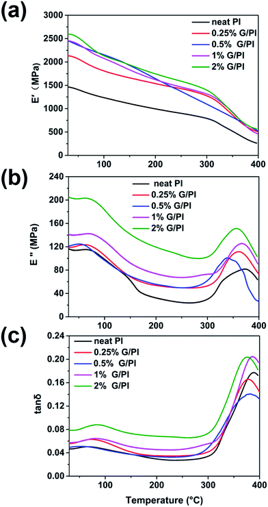 | ||
Fig. 7 DMA results of polyimide and polyimide/graphene nanocomposites as a function of graphene content; (a) storage modulus E′, (b) loss modulus E′′, and (c) tan![[thin space (1/6-em)]](https://www.rsc.org/images/entities/char_2009.gif) δ as a function of temperature. δ as a function of temperature. | ||
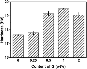
Given the high modulus of graphene and good dispersion of graphene in the polyimide matrix, we expect that the hardness of polyimide will be increased with the addition of graphene. Fig. 8 shows the Vickers hardness of the PI/G composites as a function of graphene content. When a load of 100 N was applied in the Vickers hardness test, the hardness of pure PI was 17.64 HV. As the mass fraction of graphene was 0.25%, the hardness slightly increased by ca. 0.15 HV compared to that of neat PI. When the graphene content was above 0.5%, the increase in the hardness of PI composites was obvious; it went up 19.52 HV at 1% graphene content, the point at which the hardness reached its maximum. The significant increase in the hardness for PI/G composite can be attributed to the existence of much stiffer graphene in the polymer matrix. It was also observed that the hardness of PI composite containing 2% graphene slightly decreased, probably due to the film defects caused by the aggregation of graphene nanosheets during the thermal imidization.
3.4 Thermal properties of PI/G composite films
To study the effects of graphene on the thermal stability of polyimide, thermogravimetric (TGA) and derivative thermogravimetric (DTG) analyses were conducted in air with temperature ranging 25–800 °C. Fig. 9 shows the TGA and DTG curves of the polyimide and polyimide/graphene nanocomposites. As can be seen from the TGA curves in Fig. 9a, there is almost no weight loss below 400 °C and the weight loss of polyimide was shifted to a higher temperature by adding graphene into the polyimide matrix. The thermal stability parameters including temperatures of 10% degradation (TD10) and 50% degradation (TD50) could be obtained from the DTG curves, as listed in Table 1. For pure polyimide, the 10% and 50% weight loss temperatures were 561 and 590 °C, respectively. Moreover, the graphene/polyimide nanocomposites showed distinct increases in the TD10 and TD50, implying that graphene could increase the thermal stability of polyimide resin. In general, the thermal stability of polymer nanocomposites was higher than that of the pure polymer.23 In our PI/G nanocomposites, the trapping of the PI polymer chains in the graphene nanosheets could contribute to the increase in the thermal stability of composites at very low graphene content (0.25%).24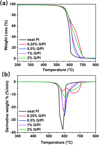 | ||
| Fig. 9 (a) TGA and (b) DTG curves of polyimide and graphene/polyimide nanocomposites as a function of temperature. | ||
| Sample | TD10 (°C) | TD50 (°C) |
|---|---|---|
| Neat PI | 561 | 590 |
| 0.25% G/PI | 573 | 592 |
| 0.5% G/PI | 571 | 602 |
| 1% G/PI | 571 | 600 |
| 2% G/PI | 567 | 606 |
3.5 Friction and wear tests of the PI/G nanocomposite films
The coefficient of friction (COF) tests of neat PI and PI/G nanocomposites were carried out under dry conditions at 2 Hz sliding frequency and an applied load of 3 N, and the results of COF against time are shown in Fig. 10a. Neat PI has a COF value of 0.45, the COF of PI/G nanocomposites varied from 0.27 to 0.43 with the mass faction of graphene ranging from 0.25 to 2 wt% and it was the lowest for 1 wt% graphene/PI composite (Fig. 10b). However, when the graphene content reached to 2 wt%, the fiction coefficient showed a level similar to that of neat PI probably due to the poor dispersion of graphene. The reason for the decrease in the COF for PI/G composites can be explained on the basis of the self-lubricity and high thermal conductivity of graphene, which was verified by the other graphene-based polymer nanocomposites, such as epoxy/graphene and rubber/graphene.25–27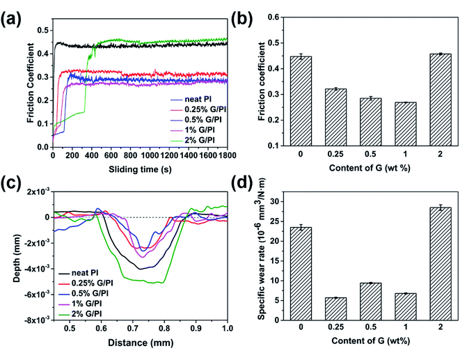 | ||
| Fig. 10 Coefficient of friction (a) and (b); wear depth (c) and wear rate (d) of PI and PI/G nanocomposites at 2 Hz sliding frequency and an applied load of 3 N. | ||
The wear of neat PI and graphene-reinforced PI was determined by measuring the depth and wear rate of scars. Fig. 10c and d display the variation of wear depth and wear rate with graphene content. The wear depth and wear rate decreased when the mass fraction was less than 1%. Moreover, the wear rate of PI composite with 0.25% graphene was measured to be 0.56 × 10⁻⁵ mm3 N−1 m−1, which is reduced by 76% in comparison with that of neat PI (2.30 × 10⁻⁵ mm3 N−1 m−1). In the abovementioned cases, reduction in the wear depth and wear rate can be attributed to the improvement in the mechanical properties of composites and the formation of transfer films with the addition of graphene, which could reduce the distortion and fragmentation of the PI composites and result in a decrease in the wear depth and wear rate.28 However, for the PI composite with 2% graphene, the wear depth and wear rate were even higher than those of neat PI. The reason for this phenomenon is probably that the aggregated graphene decreased the wear resistance of the corresponding PI/G nanocomposites.
Further, SEM was employed to investigate the worn surfaces of neat PI and PI/G. As shown in Fig. 11a, the worn surfaces of neat PI and PI/G exhibited completely different morphologies. Neat PI showed a relatively flat worn surface with a wear width of ca. 0.29 mm, displaying signs of an adhesive wear.8 However, the worn surface of PI/G nanocomposites containing 0.25%, 0.5%, and 1% graphene showed a narrow wear width and typical fatigue deformations (Fig. 11b–d, marked by a red ellipse), implying that the type of wear changed from an adhesion wear to a fatigue wear. For PI composite containing 2% graphene, the wear width was similar to that of the neat PI, demonstrating that the aggregation of graphene deteriorated the tribological performance.29,30
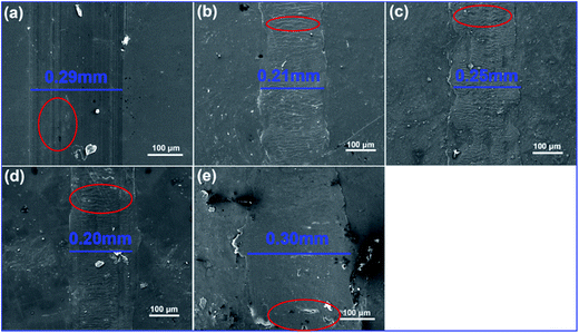 | ||
| Fig. 11 SEM images for the worn surface of (a) neat PI, (b) 0.25% G/PI, (c) 0.5% G/PI, (d) 1% G/PI, and (e) 2% G/PI. | ||
4. Conclusion
In this study, graphene-based PI nanocomposites were prepared by in situ condensation of PDMA, ODA and AT-functionalized graphene in DMAc, following subsequent thermal imidization at elevated temperatures. Aniline trimer was used as a graphene dispersant to enable the exfoliation of graphene and increase interfacial interactions between the graphene nanosheets and polyimide matrix. The XRD analysis and TEM observations showed that graphene was homogenously dispersed in the PI matrix. The incorporation of a small amount of AT-functionalized graphene significantly improved the mechanical and thermal properties of the composites, as observed by DMA and TGA analysis. Further, the incorporation of a small amount of graphene (0.25–1 wt%) exhibited reduced friction coefficients and wear rates. The improvements in the friction and wear characteristics of the PI/G composites were attributed to the improvement of mechanical properties and the formation of transfer film with the incorporation of graphene nanosheets. Considering the superior mechanical properties and tribological performance, PI/G composites prepared in this study show promising applications as wear-resistant and self-lubricating materials.Acknowledgements
The authors gratefully acknowledge the financial support provided by the National Key Basic Research Program (No. 2014CB643302), Strategic Leading Science & Technology Programme (XDA13040600) and “One Hundred Talented People” of the Chinese Academy of Sciences (Y60707WR04).References
- T. Stieglitz, M. Schuettler and J. U. Meyer, Biomed. Microdevices, 2000, 2, 283–294 CrossRef.
- P. H. C. Camargo, K. G. Satyanarayana and F. Wypych, Mater. Res., 2009, 12, 1–39 CrossRef CAS.
- D. J. Liaw, K. L. Wang, Y. C. Huang, K. R. Lee, J. Y. Lai and C. S. Ha, Prog. Polym. Sci., 2012, 37, 907–974 CrossRef CAS.
- S. Yijun, M. Liwen, F. Xin and L. Xiaohua, J. Appl. Polym. Sci., 2011, 121, 1574–1578 CrossRef.
- G. Czeremuszkin, M. Latreche and M. Wertheimer, Nucl. Instrum. Methods Phys. Res., Sect. B, 2001, 185, 88–99 CrossRef CAS.
- L. Cao, Q. Sun, H. Wang, X. Zhang and H. Shi, Composites, Part A, 2015, 68, 140–148 CrossRef CAS.
- O. K. Park, J. Y. Hwang, M. Goh, J. H. Lee, B. C. Ku and N. H. You, Macromolecules, 2013, 46, 3505–3511 CrossRef CAS.
- T. Huang, Y. Xin, T. Li, S. Nutt, C. Su, H. Chen, P. Liu and Z. Lai, ACS Appl. Mater. Interfaces, 2013, 5, 4878–4891 CAS.
- P. Liu, Z. Yao, L. Li and J. Zhou, Polym. Compos., 2016, 37, 907–914 CrossRef CAS.
- J. Y. Wang, S. Y. Yang, Y. L. Huang, H. W. Tien, W. K. Chin and C. C. M. Ma, J. Mater. Chem., 2011, 21, 13569 RSC.
- T. Huang, R. Lu, C. Su, H. Wang, Z. Guo, P. Liu, Z. Huang, H. Chen and T. Li, ACS Appl. Mater. Interfaces, 2012, 4, 2699–2708 CAS.
- V. Georgakilas, M. Otyepka, A. B. Bourlinos, V. Chandra, N. Kim, K. C. Kemp, P. Hobza, R. Zboril and K. S. Kim, Chem. Rev., 2012, 112, 6156–6214 CrossRef CAS PubMed.
- D. Sundeep, S. D. Ephraim and N. Satish, IJIRAE, 2014, 1, 1–7 Search PubMed.
- J. Fei, W. Luo, J. F. Huang, H. Ouyang, Z. Xu and C. Yao, Tribol. Int., 2015, 87, 91–97 CrossRef CAS.
- O. K. Park, S. G. Kim, N. H. You, B. C. Ku, D. Hui and J. H. Lee, Composites, Part B, 2014, 56, 365–371 CrossRef CAS.
- C. J. Weng, C. H. Chang, C. W. Peng, S. W. Chen, J. M. Yeh, C. L. Hsu and Y. Wei, Chem. Mater., 2011, 23, 2075–2083 CrossRef CAS.
- C. Min, P. Nie, H. J. Song, Z. Zhang and K. Zhao, Tribol. Int., 2014, 80, 131–140 CrossRef CAS.
- M. Fang, K. Wang, H. Lu, Y. Yang and S. Nutt, J. Mater. Chem., 2009, 19, 7098 RSC.
- G. Y. Kim, M. C. Choi, D. Lee and C. S. Ha, Macromol. Mater. Eng., 2012, 297, 303–311 CrossRef CAS.
- B. Shen, W. Zhai and W. Zheng, Adv. Funct. Mater., 2014, 24, 4542–4548 CrossRef CAS.
- L. Ma, G. Wang and J. Dai, J. Appl. Polym. Sci., 2016, 133 Search PubMed.
- Y. T. Chern and H. C. Shiue, Macromol. Chem. Phys., 1998, 199, 963–969 CrossRef CAS.
- A. Leszczyńska, J. Njuguna, K. Pielichowski and J. Banerjee, Thermochim. Acta, 2007, 453, 75–96 CrossRef.
- I. H. Tseng, Y. F. Liao, J. C. Chiang and M.-H. Tsai, Mater. Chem. Phys., 2012, 136, 247–253 CrossRef CAS.
- S. H. Song, K. H. Park, B. H. Kim, Y. W. Choi, G. H. Jun, D. J. Lee, B. S. Kong, K. W. Paik and S. Jeon, Adv. Mater., 2013, 25, 732–737 CrossRef CAS PubMed.
- J. Wang, H. Jia, Y. Tang, D. Ji, Y. Sun, X. Gong and L. Ding, J. Mater. Sci., 2013, 48, 1571–1577 CrossRef CAS.
- M. Hernández, M. D. M. Bernal, R. Verdejo, T. A. Ezquerra and M. A. López-Manchado, Compos. Sci. Technol., 2012, 73, 40–46 CrossRef.
- M. Zhang, Y. Li, Z. Su and G. Wei, Polym. Chem., 2015, 6, 6107–6124 RSC.
- D. Liu, W. Zhao, S. Liu, Q. Cen and Q. Xue, Surf. Coat. Technol., 2016, 286, 354–364 CrossRef CAS.
- P. A. Okafor and J. O. Iroh, J. Mater. Chem. A, 2015, 3, 17230–17240 CAS.
| This journal is © The Royal Society of Chemistry 2017 |

