 Open Access Article
Creative Commons Attribution 3.0 Unported Licence
Electrospun three-layered polymer nanofiber-based porous carbon nanotubes for high-capacity energy storage†
Jun Seop Lee‡
ab,
Jaemoon Jun‡a,
Sunghun Choc,
Wooyoung Kima and
Jyongsik Jang*a
aSchool of Chemical and Biological Engineering, College of Engineering, Seoul National University, 599 Gwanangno, Gwanakgu, Seoul, 151-742, Korea. E-mail: jsjang@plaza.snu.ac.kr; Fax: +82-2-888-1604; Tel: +82-2-880-7069
bInstitute for Molecular Engineering, University of Chicago, 5640 South Ellis Avenue, Chicago, IL 60637, USA
cSchool of Chemical Engineering, Yeungnam University, 280 Daehak-Ro, Gyeongsan 38541, Korea
First published on 23rd December 2016
Abstract
Recently, carbon nanomaterials are attractive for various applications owing to the benefits derived from their high electrical conductivity, chemical stability and large surface to volume ratio. However, the fabrication process of carbon nanomaterials is complicated and exhibits low productivity. Here we report the facile one-pot synthesis of highly porous 1D carbon nanotubes based on three-layered polymer nanofibers by using a dual-nozzle co-electrospinning technique to apply to an energy storage device. Specific capacitance (CG) of the porous carbon nanotube-based electrode is 401 F g−1, which is larger than that of the other carbon nanomaterials. Furthermore, the porous carbon nanotube exhibits excellent rate capability and cycle stability due to micro-/mesopores in the carbon structure enhancing the active surface area between carbon and the ions of the electrolytes. This unique fabrication technique is an effective approach for forming large scale highly porous carbon nanomaterials for diverse electrochemical applications.
1. Introduction
Carbon-based nanomaterials have led to the development of various electrical and electrochemical device applications on account of their favorable uniform structure, high electric conductivity and chemical stability.1–5 Among the different morphologies of carbons, one-dimensional (1D) carbon nanomaterials have received considerable attention owing to their unique characteristics that are high surface to volume ratio and enhanced electrical conductivity.6–10 Therefore, a lot of researches have been conducted to fabricate 1D carbon nanomaterial with well controlled chemical composition and morphology using self-assembly solvothermal synthesis, chemical vapor deposition, and nanocasting.11–15 However, there are several limitations of these synthesis that are rigid reaction conditions, high cost, and complicated synthetic steps.14,15 One of the alternative 1D nanostructure synthetic process, electrospinning is an effective and convenient method to fabricate uniform and large-scale nanofibers.16–20 Especially, 1D carbon nanofibers originated from electrospinning process are increasing of interest in electrochemical devices for the following reasons: (1) the 1D geometry permits efficient electron transport along the longitudinal direction;21,22 (2) the 1D structure increases the ion flux at the interface between the active material and the electrode because of the large surface-to-volume ratio with the electrolyte and the reduced ion diffusion length.23,24 Moreover, co-electrospinning technique, using phase separated polymer solutions (i.e., PMMA/PAN, PAN/PVP, and PS/PAN), is used to produce unique structure of porous carbon nanofibers.25–29As promising practical application of porous carbon nanostructures, supercapacitor (SC) device, one of energy storage system, is used because of predominant mechanical strength, high surface area and pores in the carbon structure.30–32 The capacitance of the SC is caused by the pore size of the carbon structure and active surface area of the electrode. In detail, micropores (<2 nm) enhance surface area and provide more active sites for adsorption of electrolyte, while mesopores (2–50 nm) improve penetration of electrolyte in the carbon structure for high power density.33–35 In addition, macropores (>50 nm) are important to electrolyte transportation into the carbon electrode and ratio enhancement of electrode utilization.36,37 Therefore, hierarchical porous carbon nanofibers with micro-/mesopores are needed in SC electrode. Recently, lots of efforts have been conducted to rational design and preparation of hierarchical porous carbon nanofibers by using several template methods to improve electrochemical performance of SC electrode.38–40 However, the techniques using template have several limitations that are complexity and low output.41,42 To solve these problems, further research with facile and large output is required to appreciate porous carbon nanofibers.
Herein, we report a new facile and cost-effective strategy for fabricating highly porous carbon nanotubes. A dual-nozzle co-electrospinning technique is described that can control the diameter of tube and density of micropores in the tube structure precisely. First, three-layered polymer nanofibers, composed of PMMA (first layer), PAN (second layer), and PVP (third layer), were formed using dual-nozzle co-electrospinning method. Then, highly porous carbon nanotubes, contained micro- and mesopores, were fabricated through following heat treatment. The highly porous carbon nanotubes were used as electrode materials for supercapacitors exhibited a specific capacitance of 401 F g−1, which is higher than that of pristine carbon nanotubes or other carbon nanofibers. SC electrode based on porous carbon nanotubes also exhibited not only high cycle stability but also excellent rate capability originated from inner micro- and mesopores in the carbon structure. To the best of our knowledge, no reports have described the manufacture of highly porous carbon nanotubes using the dual-nozzle co-electrospinning technique.
2. Experimental section
2.1 Materials
Poly(acrylonitrile) (PAN, Mw = 150![[thin space (1/6-em)]](https://www.rsc.org/images/entities/char_2009.gif) 000), poly(vinylpyrrolidone) (PVP, Mw = 1
000), poly(vinylpyrrolidone) (PVP, Mw = 1![[thin space (1/6-em)]](https://www.rsc.org/images/entities/char_2009.gif) 300
300![[thin space (1/6-em)]](https://www.rsc.org/images/entities/char_2009.gif) 000), and poly(methyl methacrylate) (PMMA, Mw = 350
000), and poly(methyl methacrylate) (PMMA, Mw = 350![[thin space (1/6-em)]](https://www.rsc.org/images/entities/char_2009.gif) 000) were purchased from Aldrich Chemical Co. N,N-Dimethylformamide (DMF, Aldrich) was used as the solvent in the PAN, PVP, and PMMA solutions.
000) were purchased from Aldrich Chemical Co. N,N-Dimethylformamide (DMF, Aldrich) was used as the solvent in the PAN, PVP, and PMMA solutions.
2.2 Fabrication of highly porous carbon nanotubes
Each PAN and PVP solution was prepared by dissolving 1.0 g of polymer in 10 mL of DMF at 80 °C for 1 h with vigorous stirring. Then, the PAN and the PVP solutions were mixed at 80 °C for 3 h to fabricate outer part of electrospinning polymer solution. PMMA solution was prepared by dissolving 0.7 g of PMMA in 10 mL of DMF at 60 °C for 2 h with vigorous stirring to apply inner part of electrospinning polymer solution. The mixed polymer solution (PAN and PVP) was loaded into a syringe pump (KD Scientific, U.S.A) and then pumped through the outer part of the dual metal nozzle (20 G needle; inner diameter: 0.5 mm). PMMA polymer solution was injected from syringe pump through the inner part of dual-nozzle (27 G needle; inner diameter: 0.1 mm). A voltage of 15 kV was applied between the metal nozzle and the collector. The distance between the nozzle and collector was 15 cm and the flow rate of syringe pumps were maintained at 5 μL min−1. The electrospun core–shell nanofibers were carbonized at 800 °C for 1 h in nitrogen gas flow at a heating rate of 5 °C min−1.2.3 Characterization and electrochemical measurement
A JEOL 6700 was used to obtain field-emission scanning electron microscopy (FE-SEM) images. Transmission electron microscopy (TEM) and high-resolution transmission electron microscopy (HR-TEM) images were obtained using a JEOL JEM-200CX and a JEOL JEM-3010, respectively. During sample preparation, materials diluted in ethanol were cast onto a copper grid. X-ray diffraction (XRD) was recorded using a M18XHF SRA (MAC Science Co.). A focused ion beam (FIB) system (FET Helios 650) was used to examine the fabric structure. CV/galvanostatic charge–discharge curves, electrochemical impedance spectroscopy (EIS, frequency range: 200 kHz to 20 mHz; amplitude: 5 mV) and cycling stability measurements were conducted using an electrochemical workstation (ZIVE SP2).3. Results and discussion
3.1 Fabrication of highly porous carbon nanotubes
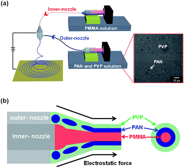
Fig. 1a and S1† illustrates the overall diagram of dual-nozzle co-electrospinning process that consists of high voltage supplier, ground, and dual-nozzle connected with different polymer solutions. To fabricate three-layered polymer nanofiber as starting material, each polymer solution was connected to dual-nozzle that was PMMA (inner-nozzle) and PAN/PVP mixed solutions (outer-nozzle). In the mixed polymer solution, PVP and PAN are separated as continuous (surrounding) and discontinuous (droplet) phases owing to the incompatibility of the two polymers as a result of their intrinsic properties, in particular, their viscosity (inset of Fig. 1a).25,26 Then, the mixed PAN/PVP solution was electrospun by the outer part of the dual-nozzle, while PMMA solution was electrospun through the inner nozzle onto the collector under a continuous high voltage. During electrospinning process, the shell fluid (PVP and PAN mixed solution) forms a sheath around the core fluid (PMMA solution), which entrains and stabilizes of the core fluid against break-up into droplets by this process such as the Rayleigh instability. In other words, the shell mixed polymer (PAN and PVP) can serve as a template for the core polymer (PMMA) leading to cable-type structures.27,28More specifically, the formation mechanism of three-layered electrospun nanofiber is suggested as following (Fig. 1b). First, a stable Taylor cone is formed, when the proper combination of optimum electrospinning conditions. Then, three-layered co-axial jet is formed through high voltage applying between outer-part of metallic dual-nozzle and ground. The jet is subsequently stretched by electrostatic forces to generate three-layered co-axial nanofibers. The elongation of the sheath is mainly driven by electrostatic repulsions of the surface charges, during the spinning process. Moreover, rapid stretching of the sheath can cause phase separation of the shell layer (PAN/PVP) and strong viscous stress, which passes on to the PMMA core. Tangential to the jet line, the shear stress stretch the PMMA phase and elongation it along with the sheath solution via mechanism such as viscous dragging and contact friction.
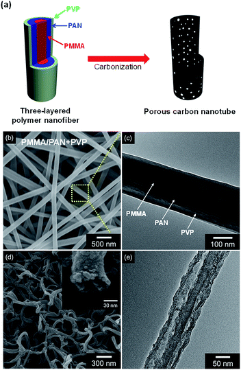
The as prepared nanofibers formed three layered (PMMA: first layer; PAN: second layer; PVP: third layer) with ca. 200 nm diameter (Fig. 2a–c). The electrospun three-layered nanofibers were then carbonized at a rate of 5 °C min−1 and maintained for 1 h at 800 °C under Ar flow. During this process, PVP and PMMA decomposed and PAN transferred to graphite carbon. The as fabricated porous carbon nanotubes (denoted as PCNT_4) exhibited ca. 80 nm-diameter and ca. 7 nm-thickness with small pores generation in the carbon structure (Fig. 2d and e).
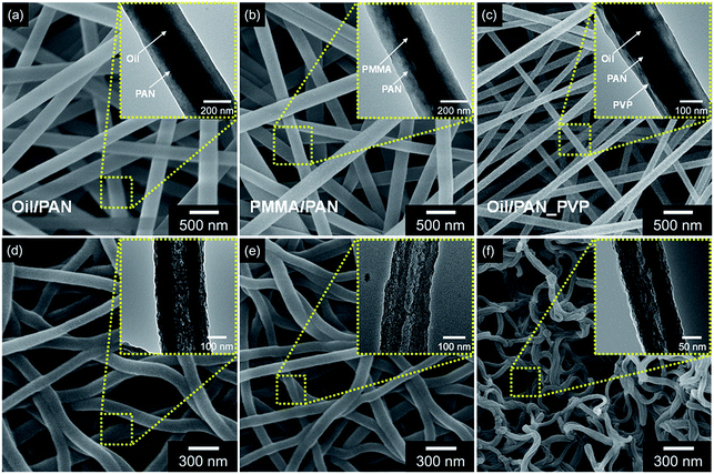
Moreover, other carbon nanotubes from different composition of co-axial nanofibers were also suggested to confirm the effect of each layer (PMMA and PVP) for formation of carbon architectures (Fig. 3). First, carbon nanotubes originated from without PVP layer (PMMA/PAN) are suggested in the Fig. 3b and e. The electrospun core–shell nanofibers exhibited ca. 380 nm-diameter that is larger than that of three-layered nanofibers (ca. 200 nm). The following carbon nanotubes (denoted as PCNT_2) also displayed larger diameter (ca. 180 nm) than that of highly porous carbon nanotubes (ca. 80 nm). Second, carbon nanotubes from mineral oil as core phase (mineral oil/PAN and PVP) are also demonstrated. The electrospun nanofibers represented three-layered co-axial architecture with ca. 230 nm-diameter, similar size to three-layered nanofibers (Fig. 3c). However, the morphology of the carbonized nanotubes, denoted as PCNT_3, revealed uniform surface architecture without roughness and higher thickness (ca. 20 nm) than that of PMMA core nanofiber derived carbon (Fig. 3f). Additionally, co-axial nanofibers composed of mineral oil and PAN also suggested with ca. 400 nm-diameter and following carbonized nanotubes (denoted as PCNT_1) revealed ca. 210 nm of diameter without small pores in the structure (Fig. 3a and d). Therefore, the PVP layer cause reducing diameter of nanofibers and PMMA generate small pores in the carbon structure.
3.2 Characterization of highly porous carbon nanotubes
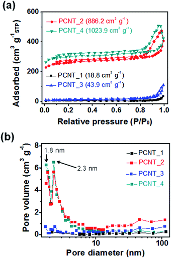
To confirm the microstructure change of the carbon nanotubes with different components, Brunauer–Emmett–Teller (BET) and Barrett–Joyner–Halenda (BJH) measurements were performed. Fig. 4a present the N2 adsorption/desorption isotherms obtained using the BET method for the various carbon nanotubes. The surface area increased with emerging small pores in the structure and decreasing diameter of nanotubes as followings: 18.8 m2 g−1 for PCNT_1 (oil/PAN); 886.2 m2 g−1 for PCNT_2 (PMMA/PAN); 43.9 m2 g−1 for PCNT_3 (oil/PAN + PVP); 1023.9 m2 g−1 for PCNT_4 (PMMA/PAN + PVP). In particular, this rapid increment in the surface area was caused by the emergence small pores in the carbon structure with adding PMMA core layer rather than diminishing diameter by using PVP shell layer; the surface area of PCNT_2 (886.2 m2 g−1) was ca. 20 times larger than that of the PCNT_3 (43.9 m2 g−1). Therefore, the small pores originated from decomposing of PMMA core layer had a significant effect on the surface area of carbon nanostructure rather than decreasing diameter from PVP addition. Moreover, pore distribution of different carbon nanotubes was suggested through BJH method as demonstrated in Fig. 4b. The peaks at 1.9 nm and 2.3 nm emerged with PMMA core addition. Therefore, these peaks are originated from porous structure that caused to increase surface area of carbon nanotubes drastically.The chemical composition of the PCNTs was also changed with containing PMMA core phase in the electrospun nanofiber. Fig. 5 suggests high-resolution X-ray photoelectron spectroscopy (XPS) spectra for the C 1s region around 285 eV for each PCNT. First, PCNTs without PMMA core phase (PCNT_1 and PCNT_3) were deconvoluted into four components as follows: the 284.3 eV peak corresponds to C![[double bond, length as m-dash]](https://www.rsc.org/images/entities/char_e001.gif) C bonds, the 285.3 eV peak corresponds to C–C bonds, the 286.6 eV corresponds to C–O bonds, and ca. 290 eV corresponds to shake-up satellite graphite carbon. Second, PCNTs with PMMA core phase (CPNT_2 and CPNT_4) were also deconvoluted into four components: C
C bonds, the 285.3 eV peak corresponds to C–C bonds, the 286.6 eV corresponds to C–O bonds, and ca. 290 eV corresponds to shake-up satellite graphite carbon. Second, PCNTs with PMMA core phase (CPNT_2 and CPNT_4) were also deconvoluted into four components: C![[double bond, length as m-dash]](https://www.rsc.org/images/entities/char_e001.gif) C, C–C, C–O, and pi
C, C–C, C–O, and pi![[double bond, length as m-dash]](https://www.rsc.org/images/entities/char_e001.gif) pi* bonds. However, the peak for C–O at 286.6 eV drastically increased owing to heat decomposition of PMMA core phase with small pore formation in the carbon surface during carbonization process.
pi* bonds. However, the peak for C–O at 286.6 eV drastically increased owing to heat decomposition of PMMA core phase with small pore formation in the carbon surface during carbonization process.
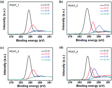 | ||
| Fig. 5 X-ray photoelectron spectroscopy (XPS) C 1s patterns of different PCNTs: (a) PCNT_1, (b) PCNT_2, (c) PCNT_3, and (d) PCNT_4. | ||
3.3 Electrochemical performance of highly porous carbon nanotubes
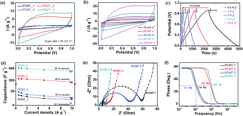
To assess the potential of the porous carbon nanotubes as electrode materials for supercapacitors (SCs), the electrochemical properties were investigated using a three-electrode cell, specifically, a 1 M H2SO4 aqueous electrolyte with Pt counter electrode and an Ag/AgCl reference electrode. First, cyclic voltammetry (CV) curves were measured at a scan rate of 50 mV s−1 in the voltage from 0 V to 1 V for different carbon nanotube electrodes (Fig. 6a). The CV curves display rectangular-like shape on account of double layer formation at the electrode–electrolyte interface and no redox reaction during charge/discharge reactions. The area under the CV curves increased with formation of small pores and decrease of diameters originated from decomposition of PMMA and PVP layer in the nanofiber structure. In particular, the current density of PCNT_4 was 11.25 A g−1 that was ca. 10-fold large than that of PCNT_1 (without small pores and diminishing diameter). In addition, increasing amount of current density of PCNT_3 (with only small pores) was higher than that of PCNT_2 (with only small diameter) owing to small pores more enhanced active surface area between the electrode and ions of electrolyte.Furthermore, PCNT_4 also displayed rectangular-like CV curves for increasing scan rate (10 to 100 mV s−1) without area under the CV curves; this indicated ideal capacitive behavior and fast charge–discharge properties (Fig. 6b). The rectangular-like shape at the higher scan rate is due to the presence of small pores. The solvated cation (H3O+) and anion (SO42−) in H2SO4 solution have ion sizes of 0.42 nm and 0.53 nm, respectively.43,44 These ions can easily diffuse through the small pores with size larger than 1 nm. On the other hand, other carbon nanotubes without small pores presented diminishing area under the CV curves with increasing scan rate as shown in the Fig. S2.†
Galvanostatic charge–discharge measurements were carried out on the different electrodes to obtain more detailed information related to the specific capacitance. The galvanostatic curves of PCNT_4 reasonably symmetric and linear over time with enhancing current density, further demonstrating ideal capacitive behavior and rapid charge–discharge characteristics (Fig. 6c). However, other carbon nanotubes without small pores displayed slightly asymmetric shapes with increasing current density (Fig. S3†). In addition, the IR drop of curves increased with enhancing current density from 0.004 V (0.5 A g−1) to 0.08 V (10 A g−1).
Fig. 6d shows the specific capacitance (CG) calculated from the galvanostatic charge–discharge curves as a function of the current density. The calculated specific capacitance of the electrodes at 2 A g−1 as follows: 31.1 F g−1 for PCNT_1; 313 F g−1 for PCNT_2; 39.2 F g−1 for PCNT_3; 401 F g−1 for PCNT_4. As the current density increased from 0.5 A g−1 to 10 A g−1, the capacitance retention of the PCNT_4 (89%) was larger than that without small pores (PCNT_1: 61%; PCNT_2: 59%).
Electrochemical capacitance spectra (EIS) measurements were used to further investigate the electrochemical and structural characteristics of the electrodes. Fig. 6e show the Nyquist plot of the electrodes with 1 M-H2SO4 electrolyte. A change of the midrange frequency impedances in electrodes gives rise to visible knee frequency, characteristics of transition from frequency-dependent diffusion resistance to pure capacitive behavior.45 At high frequencies, the electrode behaves like resistance (R). The intercept and size of the semicircle are related to the equivalent series resistance (ESR) and size of the semicircle are related to the equivalent series resistance (ESR) and charge transfer resistance at the interface between the electrode and electrolyte (Rct), respectively. The ESR and Rct also reduced by the small pores formation and decreasing diameter as following: 4.38 Ω (ESR)/54.06 Ω (Rct) for PCNT_1, 1.38 Ω (ESR)/8.52 Ω (Rct) for PCNT_2, 5.09 Ω (ESR)/37.33 Ω (Rct) for PCNT_3, 0.95 Ω (ESR)/7.13 Ω (Rct) for PCNT_4, respectively.
Fig. 6f displays the Bode phase plot of the electrodes. The capacitor response frequency for diverse electrodes at a phase angle of −45° was as follows: 1.4 Hz for PCNT_1; 76 Hz for PCNT_2; 1.1 Hz for PCNT_3; 104 Hz for PCNT_4. Therefore, the calculated relaxation time constant (τ0) that indicates pore capacity behavior and stored energy accessibility of frequencies blow this frequency was calculated to be 0.71 s for PCNT_1, 13 ms for PCNT_2, 0.91 s for PCNT_3, and 9.6 ms for PCNT_4, respectively. At low frequencies (0.2 Hz for PCNT_1, 10.1 Hz for PCNT_2, 0.16 Hz for PCNT_3, and 12.6 Hz for PCNT_4), the phase angles for electrodes are ca. −90° which is close to ideal for capacitor electrodes.
Moreover, the cycle stability of the electrodes suggested as a function of the cycle number at a 2 A g−1 current density over the constant voltage range from 0 to 1 V (Fig. 7). All of carbon nanotubes displayed large retention capacitance (ca. 97%) after 5000 cycles (96% for PCNT_1; 97% for PCNT_2; 96% for PCNT_3; 97% for PCNT_4) on account of electron double layer energy storage mechanism of carbon material. In addition, energy storage ability of the PCNT_4, as supercapacitor electrode materials, is larger than that of other carbon materials (Table 1).
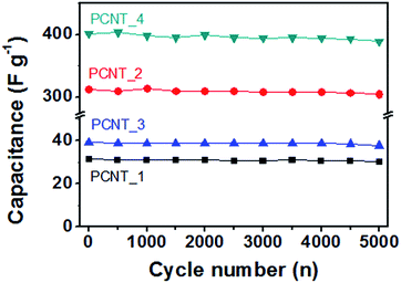 | ||
| Fig. 7 Cycling performance of the different PCNTs at 2 A g−1 of current density (black: PCNT_1; red: PCNT_2; blue: PCNT_3; green: PCNT_4). | ||
| Material | Synthesis | Specific capacitance (CG) | Cycle stability | Reference |
|---|---|---|---|---|
| MnO2/CNF/rGO | Electrospinning/Hummer's method | 174 F g−1 | 91% (500 cycles) | 2 |
| Hollow carbon fibers | Cotton carbonization | 355 F g−1 | 92.4% (4000 cycles) | 8 |
| Macro-channeled activated carbon | Luffa sponge carbonization | 249 F g−1 | 87.6% (5000 cycles) | 11 |
| Carbon nanofibers | Electrospinning | 130.7 F g−1 | — | 30 |
| Porous carbon fibers | Electrospinning/activation | 197 F g−1 | — | 40 |
| PCNT_4 | Dual-nozzle co-electrospinning | 401 F g−1 | 89% (5000 cycles) | This work |
4. Conclusions
In summary, highly-porous carbon nanotubes were fabricated though facile dual-nozzle co-electrospinning technique. To the best of our knowledge, this is the first demonstration of the fabrication of highly porous carbon nanotubes based on dual-nozzle co-electrospinning process. This porous carbon nanotubes exhibited small pores (ca. 2 nm) in the carbon surface owing to decomposing of PMMA core phase during carbonization. Moreover, the porous carbon nanotubes exhibited small diameter originated from PVP shell layer. The resulting porous carbon nanotubes were used as electrode to prepare supercapacitors (SCs) with enhanced specific capacitance and rate capability. The small pores in the carbon structure were critical in improving the properties of SCs owing to it enlarged active surface area between carbon and ions of electrolyte. Thus, this study demonstrated an effective method to fabricate highly porous 1D carbon nanomaterials for energy storage applications.Notes and references
- Q. Wang, J. Yan and Z. Fan, Energy Environ. Sci., 2016, 9, 729 CAS.
- O. S. Kwon, T. Kim, J. S. Lee, S. J. Park, H.-W. Park, M. Kang, J. E. Lee, J. Jang and H. Yoon, Small, 2013, 9, 248 CrossRef CAS PubMed.
- J. S. Lee, D. H. Shin, J. Jun, C. Lee and J. Jang, ChemSusChem, 2014, 7, 16676 Search PubMed.
- Y. Shim and H. J. Kim, ACS Nano, 2010, 4, 2345 CrossRef CAS PubMed.
- O. N. Kalugin, V. V. Chaban, V. V. Loskutov and O. V. Prezhdo, Nano Lett., 2008, 8, 2126 CrossRef CAS PubMed.
- S. Hu, S. Zhang, N. Pan and Y.-L. Hsieh, J. Power Sources, 2014, 270, 106 CrossRef CAS.
- L. Fu, K. Tang, K. Song, P. A. Van Aken, Y. Yu and J. Maier, Nanoscale, 2014, 6, 1384 RSC.
- S. Wang, Z. Ren, J. Li, Y. Ren, L. Zhao and J. Yu, RSC Adv., 2014, 4, 31300 RSC.
- Y. Bai, Z.-H. Huang and F. Kang, Carbon, 2014, 66, 705 CrossRef CAS.
- Y. Yu, L. Gu, C. Zhu, P. A. V. Aken and J. Maier, J. Am. Chem. Soc., 2009, 131, 15984 CrossRef CAS PubMed.
- J. Li, Z. Ren, Y. Ren, L. Zhao, S. Wang and J. Yu, RSC Adv., 2014, 4, 35789 RSC.
- X. Mao, A. Hatton and G. C. Rutledge, Curr. Org. Chem., 2013, 17, 1390 CrossRef CAS.
- T. H. Hwang, Y. M. Lee, B.-S. Kong, J.-S. Seo and J. W. Choi, Nano Lett., 2012, 12, 802 CrossRef CAS PubMed.
- Y. Liang, D. Wu and R. Fu, Sci. Rep., 2013, 3, 1119 Search PubMed.
- Y. Yang, A. Centrone, L. Chen, F. Simeon, T. A. Hatton and G. C. Rutledge, Carbon, 2011, 49, 3395 CrossRef CAS.
- C. Niu, J. Meng, X. Wang, C. Hang, M. Yan, K. Zhao, X. Xu, W. Ren, Y. Zhao, L. Xu, Q. Zhang, D. Zhao and L. Mai, Nat. Commun., 2015, 6, 7402 CrossRef PubMed.
- D. Grafahrend, K.-H. Heffels, M. V. Beer, P. Gasteier, M. Moller, G. Boehm, P. D. Dalton and J. Groll, Nat. Mater., 2011, 10, 67 CrossRef CAS PubMed.
- S. Zhang, M. A. Greenfield, A. Mata, L. C. Palmer, R. Bitton, J. R. Mantei, C. Aparicio, M. O. Cruz and S. I. Stupp, Nat. Mater., 2010, 9, 594 CrossRef CAS PubMed.
- Z. Zhang, X. Li, C. Wang, L. Wei, Y. Liu and C. Shao, J. Phys. Chem. C, 2009, 113, 19397 CAS.
- S. M. Park and D. S. Kim, Adv. Mater., 2015, 27, 1682 CrossRef CAS PubMed.
- N. G. Sahoo, S. Rana, J. W. Cho, L. Li and S. H. Chan, Prog. Polym. Sci., 2010, 35, 837 CrossRef CAS.
- C. A. Bonino, K. Efimenko, S. I. Jeong, M. D. Krebs, E. Alsberg and S. A. Khan, Small, 2012, 8, 1928 CrossRef CAS PubMed.
- X. Lu, C. Wang and Y. Wei, Small, 2009, 5, 2349 CrossRef CAS PubMed.
- S. W. Lee, H. J. Lee, J. H. Choi, W. G. Koh, J. M. Myoung, J. H. Hur, J. J. Park, J. H. Cho and U. Jeong, Nano Lett., 2010, 10, 347 CrossRef CAS PubMed.
- A. V. Bazilevsky, A. L. Tarin and C. M. Megaridis, Langmuir, 2007, 23, 2311 CrossRef CAS PubMed.
- J. S. Lee, O. S. Kwon, S. J. Park, E. Y. Park, S. A. You, H. Yoon and J. Jang, ACS Nano, 2011, 5, 7992 CrossRef CAS PubMed.
- Y. Yu, L. Gu, C. Wang, A. Dhanabalan, P. A. van Akenm and J. Maier, Angew. Chem., Int. Ed., 2009, 48, 6485 CrossRef CAS PubMed.
- J. H. Yu, S. V. Fridrikh and G. C. Rutledge, Adv. Mater., 2004, 16, 1562 CrossRef CAS.
- J. E. Diaz, A. Barrero, M. Marquez and I. G. Loscertales, Adv. Funct. Mater., 2006, 16, 2110 CrossRef CAS.
- B.-H. Kim, K. S. Yang, Y. A. Kim, Y. J. Kim, B. An and K. Oshida, J. Power Sources, 2011, 196, 10796 Search PubMed.
- J. Jun, J. S. Lee, D. H. Shin, S. G. Kim and J. Jang, Nanoscale, 2015, 7, 16026 RSC.
- Y. J. Yun, W. G. Hong, W.-J. Kim, Y. Jun and B. H. Kim, Adv. Mater., 2013, 25, 5701 CrossRef CAS PubMed.
- C. Lei, F. Markoulidis, Z. Ashitaka and C. Lekakou, Electrochim. Acta, 2013, 92, 183 CrossRef CAS.
- K. Nakagawa, S. R. Mukai, K. Tamura and H. Tamon, Chem. Eng. Res. Des., 2007, 85, 1331 CrossRef CAS.
- M. Toupin, D. Belanger, I. R. Hill and D. Quinn, J. Power Sources, 2005, 140, 203 CrossRef CAS.
- E. Frackowiak and F. Beguin, Carbon, 2001, 39, 937 CrossRef CAS.
- J. Chmiola, C. Largeot, P.-L. Taberna, P. Simon and Y. Gogotsi, Science, 2010, 328, 480 CrossRef CAS PubMed.
- W. Li, Q. Yue, Y. Deng and D. Zhao, Adv. Mater., 2013, 25, 5129 CrossRef CAS PubMed.
- C. Liang, Z. Li and S. Dai, Angew. Chem., Int. Ed., 2008, 47, 3696 CrossRef CAS PubMed.
- D. Lee, J.-Y. Jung, M.-J. Jung and Y.-S. Lee, Chem. Eng. J., 2015, 263, 62 CrossRef CAS.
- J. D. Hartgerink, E. Beniash and S. I. Stupp, Science, 2001, 294, 1684 CrossRef CAS PubMed.
- Z. Dong, S. J. Kennedy and Y. Wu, J. Power Sources, 2011, 196, 4886 CrossRef CAS.
- M. Endo, T. Maeda, T. Takeda, Y. J. Lim, K. Koshiba, H. Hara and M. S. Dresselhaus, J. Electrochem. Soc., 2001, 148, A910 CrossRef CAS.
- L. Eliad, G. Salitra, A. Soffer and D. Aurbach, J. Phys. Chem. B, 2001, 105, 6880 CrossRef CAS.
- J. Zhang and X. S. Zhao, ChemSusChem, 2012, 5, 818 CrossRef CAS PubMed.
Footnotes |
| † Electronic supplementary information (ESI) available: Apparatus of dual-nozzle co-electrospinning; CV curves of other PCNTs; galvanostatic charge/discharge curves of other PCNTs. See DOI: 10.1039/c6ra24870e |
| ‡ These authors contributed equally to this work. |
| This journal is © The Royal Society of Chemistry 2017 |

