
 Open Access Article
 This Open Access Article is licensed under a Creative Commons Attribution-Non Commercial 3.0 Unported Licence
Sorption and photodegradation under visible light irradiation of an organic pollutant by a heterogeneous UiO-67–Ru–Ti MOF obtained by post-synthetic exchange†
Ricardo Navarro Amador,
Michaël Carboni* and
Daniel Meyer
ICSM, Institut de Chimie Séparative de Marcoule UMR 5257, CEA, CNRS, ENSCM, UM, Bât 426, BP 17171, 30207 Bagnols-sur-Cèze Cedex, France. E-mail: michael.carboni@cea.fr
First published on 22nd December 2016
Abstract
The synthesis of a UiO-67 based MOF was made through the combination of two synthetic pathways, first a solvothermal synthesis in the presence of two different linkers, one for the structure and one to work as a light antenna (based on Ru), followed by a process of post-synthetic metal exchange on the coordination node to include a catalyst (Ti). This MOF has been able to remove an organic pollutant from an aqueous solution and to catalyze the degradation of the pollutant under visible light irradiation.
1. Introduction
The efficient use of solar energy is one of the biggest challenges facing scientists; numerous research groups have dedicated their work to offer solutions for this technological purpose to have more ecological and environmentally friendly energy sources and industrial processes. For that matter, several studies have focused their attention on light-driven photochemical reactions that can use solar energy to perform the photo-degradation of industrial organic pollutants with light sensitive catalysts. These compounds are widely used in the textile industry and according to several studies1–3 textile dyes represent one of the largest groups of toxic organic compounds that contribute to water pollution. While some studies have shown promising results on the degradation and the sorption of these compounds,4–7 there is still the need to work specially on the energy conversion efficiency and on the harvesting capacities of the materials since the quantum yield is low due to the limitations of the usual materials for photo-catalysis.8 Moreover, a good number of the reported systems only work on the UV spectra of light which limits the application of these materials due to a low conversion yield.8Metal–Organic Frameworks (MOFs) are a new class of porous coordination materials that have been studied for diverse applications, since the coining of the term by Yaghi and coworkers9 in 1999. MOFs have been used in many applications as gas storage,10 heterogeneous catalysis,11 extraction,12 metals separation,13,14 drug delivery15 or as photocatalysts.16 In the last example, MOFs have proven to have a great potential, mostly because during the synthesis of these materials the structure can be controlled to add a desired functionality in either the metallic cluster17 or in the organic ligand.18 This particularity allows scientist to synthesize materials with a photosensitizer and a catalytic center, all in the same crystalline structure which can be used as synthesized or can be also used as precursors to obtain porous metal oxides which can work as catalysts.19 Among the different photocatalytic MOFs that have been reported, zirconium and titanium based MOFs have attracted a lot of attention due to their high stability (thermal, mechanical or under irradiation) and their light excitation properties, respectively.
The family of the Zr-based MOFs, UiO, first reported by Lillerud and coworkers,20 has been one of the most studied MOFs in the last years due to its high stability.21 The size of the pore can vary along with the length of the iso-structural organic linkers.22,23 These properties led Lin and coworkers24 to incorporate different metal complexes of Ir, Re and Ru inside the structure of the UiO-67 by mixing during the synthesis two different ligands of similar length, the biphenyldicarboxylic acid and the metal complex anchored with the iso-structural 2,2′-bipyridine-5,5′-dicarboxylic acid. More recently, a similar material was studied by Morris and coworkers25–27 where they measured the photophysical properties of this MOF under visible light. The synthesis of heterometallic MOFs has also been achieved by the “Bifunctional Method” to obtain mixed materials based on the affinities of the reactants.28
Other interesting materials for photocatalysis are the Ti based MOFs, due to the photocatalytic properties and the low toxicity of Ti. The first Ti based MOF was the MIL-125 (ref. 29) that showed sensitivity to light under UV radiation. After, Li and coworkers18 developed an analogous of the MIL-125 where they functionalized the ligand with an amine group which allowed to shift the light absorption to the visible light spectra. However, the synthesis of Ti based MOFs is still challenging and up to this date only few relevant Ti based MOFs have been reported as the NTU-9 (ref. 30) PCN-22,31 COK-69 (ref. 32) or the Ti-MIL-101.33
Another interesting approach to obtain heterometallic MOFs is the post-synthetic exchange (PSE) process. This technique allows to exchange partially either the metallic cluster or the organic ligand of a MOF without degradation of the MOF or the loss of crystallinity34 showing the flexibility and the micro-reversibility of the MOF structure. Recently, the process of PSE has been applied on the UiO-66 (Zr6O4(OH)4L6, L = terephtalic acid) to obtain a mixed Ti/Zr MOF.17,35,36
In this work, we propose the synthesis of a Zr UiO-67 based MOF doped with a Ru complex to work as a light antenna and with Ti included by PSE to be used as photocatalyst (Fig. 1). This methodology has allowed obtaining a multi-functional material that can work slightly under UV but more importantly that make Ti visible-light active through a Ru light antenna. Sorption capacity and photodegradation activity of the material were tested towards the degradation of methylene blue (MB) in aqueous solution, the results were compared with the capacities of the precursors MOFs: UiO-67, UiO-67–Ru (modified with Ru) and UiO-67–Ti50 (modified with Ti). Synthesis of the modified UiO-67–UiO-67–Ru–TiXX (XX = % of Ti to Zr) MOF was made through classical solvothermal synthesis coupled to a post-synthetic exchange (PSME) process.
 | ||
| Fig. 1 Synthesis of photoactive UiO-67–Ru–TiXX MOF. | ||
2. Experimental section
Reagents were purchased from Sigma-Aldrich and were used as received. All ligands were fully characterized by 1H NMR and were recorded at room temperature using a 400 MHz spectrometer (Bruker). UV-visible analyses were recorded on a Shimadzu UV-36000 UV-Vis-NIR spectrometer with a diffuse reflectance measurement system. Spectrofluorometric properties were recorded and measured on a Horiba FluoroMax-4 Fluorimeter. PXRD patterns were obtained with a Bruker D8 Advance diffractometer. TGA was measured in a Mettler-Toledo TG with auto-sampler. Nitrogen physisorption measurements were performed using an ASAP 2020 at 77 K, after outgassing at 363 K during 12 hours, reaching a pressure below 1 mm Hg, and specific surface areas were calculated using the BET method.37 A FEI Quanta 200 environmental scanning electron microscope, equipped with an Everhart-Thornley Detector (ETD) and a backscattered electron detector (BSED), was used to record images with an acceleration voltage of 30 kV under high vacuum conditions. The chemical compositions of the solutions were measured by ICP-AES (Perkin Elmer Optima 2000 DV).Synthesis of the modified UiO-67–UiO-67–Ru–TiXX (XX = mol% of Ti/Zr) MOF was made through classical solvothermal synthesis coupled to a post-synthetic exchange process (Fig. 1). Details on the synthesis conditions and the characterization of complexes and ligands are provided within the ESI.†
2.1 Synthesis of UiO-67 and UiO-67–Ru
A solution of ZrCl4 (0.065 mg, 0.28 mmol) in dry DMF (5 mL) was prepared in a glass vial. To this solution it was added water (13 μL) and the mixture was sonicated during 10 minutes. Then, it was added benzoic acid (1.05 g, 8.6 mmol), 4,4′-biphenyldicarboxylic acid (bpdc) (65 mg, 0.27 mmol) and in the case of the Ru doped MOF Ru(bpy)2(5,5′-dcbpy) (13.4 mg, 0.02 mmol). The mixture was sonicated during 5 minutes before the addition of each of the reactants. The vials were then placed in an oven in static conditions at 120 °C during 72 hours. The obtained precipitate was separated by centrifugation and was washed 3 times with DMF, 3 times with ethanol and finally 2 times with diethyl ether. The crystalline solid was characterized by ICP, TGA, BET and PXRD.2.2 PSME with TiCl4THF
UiO-67 or UiO-67–Ru was placed in a glass vial by adding 10 mg of MOF into 1 mL of a solution of TiCl4 THF in DMF (9 mg mL−1). The mixture was sonicated and placed in an oven at 120 °C for 6 days. Two times a day the mixture was shaken. The solid was isolated by centrifugation and washed 3 times with fresh DMF, with ethanol, with diethyl ether and finally dried in an oven at 40 °C overnight. The crystalline solid was characterized by ICP, TGA, BET and PXRD.2.3 Dye uptake measurements
5 mg of dry MOF (UiO-67, UiO-67–Ti, UiO-67–Ru, UiO-67–Ru–Ti) were added to 5 mL of an aqueous saturated solution of MB. The mixtures were stirred in the dark until equilibrium was reached. Aliquots of the solution were taken in between to follow the variation of the dye concentration. The solutions were centrifuged to isolate the solid MOF from the liquid and the concentration was followed by UV-Vis spectroscopy. MB calibration curve was obtained by measuring the samples with different concentrations (Fig. S3†).2.4 Dye photo-degradation
5 mg of each MOF (UiO-67, UiO-67–Ti, UiO-67–Ru, UiO-67–Ru–Ti) were added to 5 mL of an aqueous solution of MB with a known concentration. The mixtures were stirred in the dark overnight to achieve adsorption equilibrium of the dye in the MOF. Then, the samples were irradiated during 4 hours under UV (250 nm) or visible light (419.5 nm) in a Rayonet RPR-100 Photochemical Reactor (400 Watts approximately). The concentration of methylene blue was determined by UV-Visible spectroscopy.3. Results and discussion
The efficiency of the exchange was qualified by XRF (Fig. S1†) and quantified by ICP-AES after digestion of the material (view ESI† for digestion procedure). Values for different MOFs are shown in Table 1. It has been possible to add up to a 50% of Ti in comparison to the amount of Zr depending on the concentration of the TiCl4 solution used for the PSE. The percentage of Ti in the MOF was graphed against the concentration of the original concentration and a linear tendency was observed (Fig. S3†). The selected concentration for further characterization was the material with an exchange of 50% of titanium (UiO-67–Ru–Ti50) due to the maximum value of exchange without loss of crystallinity that have been observed for the UiO-66.38| Samples | Concentration of TiCl4 in exchange solution (mg mL−1) | Ratio of Ti/Zr in MOF% | % Ru with respect to the ligand |
|---|---|---|---|
| UiO-67–Ru–Ti50 | 9.0 | 54.5 | 4.0 |
| UiO-67–Ru–Ti20 | 3.6 | 21.0 | 4.0 |
| UiO-67–Ru–Ti10 | 1.8 | 12.9 | 4.1 |
The amount of Ru inside the material was also quantified by ICP-AES with the digested material. The incorporation of Ru complexes is low in comparison to the amount of exchange Ti/Zr (around 5% if compared to the ligand). This low incorporation is to avoid effects on the crystalline structure of the MOF and to oversaturate the photo-activity of the MOF to ensure transference of the electrons to the catalytic centers.
PXRD analyses allowed to verify the crystallinity of the materials before and after the exchange with different concentrations of Ti. In Fig. 2 are shown the signals measured with the UiO-67 and UiO-67–Ru–Ti 10, 20 and 50. Even in low% of Ti exchange a small shift is noticeable for low values of 2θ that can be explained by the contraction of the cavities due to the change of size from Zr to Ti. This shift is enhanced with higher loadings of Ti indicating that part of the Zr in the cluster is indeed substituted by Ti as previously reported in other studies.38
 | ||
| Fig. 2 PXRD patterns for UiO-67–Ru (black) and UiO-67–Ru–Ti with different loadings of Ti MOFs (red, purple and blue). | ||
TGA results (Fig. 3) were analyzed to obtain the relation between the organic and the inorganic part for the UiO-67–Ru and UiO-67–Ru–Ti50 MOFs. The analysis of UiO-67–Ru–Ti50 shows that the percentage value of the inorganic residues increased after the exchange. This fact indicates that Ti is not only exchanging part of the cluster as shown by PXRD, but it can also be found inside the cavities of the MOF or coordinate to the cluster, since for a total exchange it would be expected a decrease of the inorganic residues (Table S1†). All the materials showed a good thermal stability with a decomposition temperature above 450 °C with no significant changes between the exchanged and the un-exchanged materials. BET surface was measured for MOFs UiO-67–Ru and UiO-67–Ru–Ti50 (Fig. S4 and S5†), the results show a decrease on the surface area after the metal exchange from 1847 m2 g−1 to 1694 m2 g−1. This is in agreement with the TGA analysis that part of the pores is occupied by the Ti. Finally, SEM images (Fig. S6†) corresponding to the different materials have the typical octahedral structure of the UiO-67; along with the SEM, it was performed the EDS analysis of the surface, however the ratio of Zr to Ti obtained showed a decrease if compared to the values obtained by ICP indicating that Ti is mainly inside the MOF structure than on the surface (Table S2†).
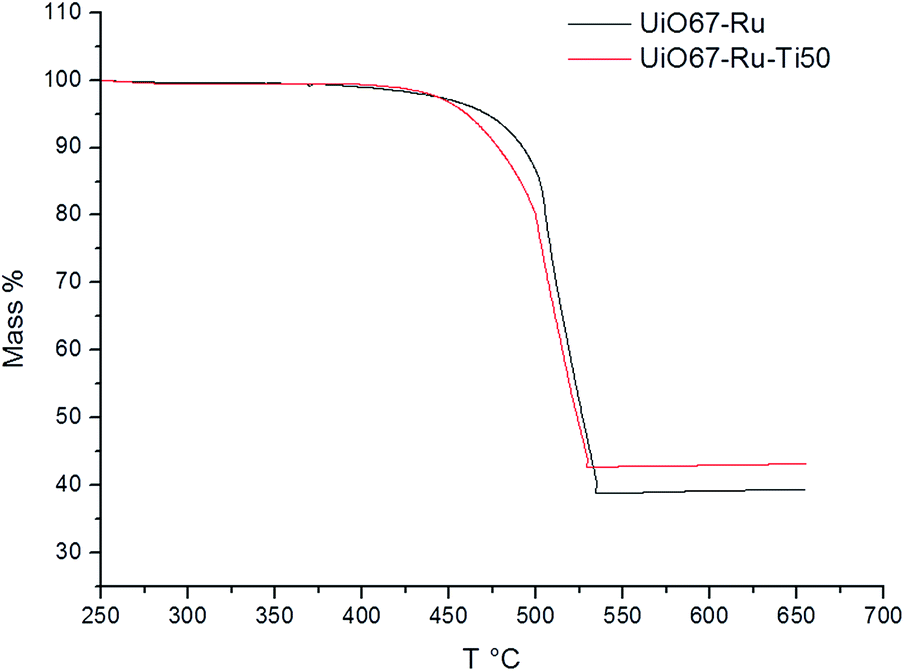 | ||
| Fig. 3 TGA of UiO-67–Ru and UiO-67–Ru–Ti50. | ||
Photocatalytic properties of the materials were measured by UV-Visible analysis and Fluorimetry. UV-visible analysis (Fig. 4) showed an increase in the signals obtained between 250 and 300 nm, values indicating a similar activity to Ti oxides in the MOF as reported in previous works.36
 | ||
| Fig. 4 UV-Vis spectra of UiO-67–Ru and UiO-67–Ru–Ti50. | ||
The Fluorimetry Analysis allowed to identify the characteristic peak of emission of Ru complexes inside the MOF. Previous characterization of the Ru(bpy)3 complexes showed that the emission maximum of these compounds is at 621 nm, while the UiO-67–Ru MOF showed a small shift to lower values of 613 nm and the exchanged UiO-67–Ru–Ti50 MOF showed a maximum of absorption at 615 nm (Fig. 5).
 | ||
| Fig. 5 Emission spectra of UiO-67–Ru and UiO-67–Ru–Ti50. | ||
Lifetime measurements were performed for the UiO-67–Ru MOF and the UiO-67–Ru–Ti50, showing a decrease on the value with the exchanged MOF. UiO-67–Ru showed a lifetime value of 3.43 × 10⁻⁷ seconds while the exchanged material showed a value of 4.52 × 10⁻⁸ seconds (Fig. S7†). The decrease on this value can be related to the proximity of Ru to the Ti catalytic center. Also, the fit was obtained with a mono-exponential fitting, indicating the presence of just one type of light interaction of the Ru complex in the MOF.
Dye sorption results are shown in Fig. S8.† With the introduction of Ru and Ti respectively, the sorption decreases considerably due to some obstructions of the MOF cavities by the Ru complex and the addition of Ti.
The adsorption data obtained was fitted to a pseudo-first and pseudo-second-order rate equations. The linear pseudo first order is represented by
| ln(qe − qt) = ln(qe) − k1t | (1) |
The linear form of the pseudo-second-order rate equation is expressed as
 | (2) |
| Parameter | UiO-67 | UiO-67–Ru | UiO-67–Ti50 | UiO-67–Ru–Ti50 |
|---|---|---|---|---|
| q e (exp.) (mg g−1) | 257 | 104 | 70.5 | 40.4 |
| k 2 [g (mg−1 min−1)] | 2.28 × 10⁻⁵ ± 9.45 × 10⁻⁷ | 5.03 × 10⁻⁵ ± 9.89 × 10⁻⁶ | 2.62 × 10⁻⁴ ± 7.53 × 10⁻⁵ | 1.06 × 10⁻³ ±2.43 × 10⁻⁴ |
| q e (calc.) (mg g−1) | 285 ± 3.83 | 111 ± 3.77 | 72.9 ± 2.58 | 42.0 ± 1.52 |
| R 2 | 0.998 | 0.992 | 0.993 | 0.993 |
The diffusion speed also seems to be affected, by prolonging the time to reach equilibrium in any of the modified MOFs, either with Ti or Ru or the combination of both.
The photo-degradation results are shown in Fig. S11† and 6 under UV and visible irradiation respectively for the different synthesized materials. It can be observed a decrease on the concentration of dyes especially with UiO-67–Ru–Ti50. This shows the increase on the photo-activity as well as on the kinetics of the degradation reaction in comparison to its precursors. These results indicate that the photocatalytic reaction is boosted by the communication of the Ru with the Ti, while the reaction takes place on the Ti centers in the MOF. This can be concluded since the activity is almost inexistent in any of the other materials (UiO-67, UiO-67–Ru or UiO-67–Ti). The catalytic degradation of MB with Ti oxides has been described in several studies39 and it is reported that this reaction takes places through the generation of ·OH radicals that can react directly with adsorbed dye molecules. An equivalent mechanism has been proposed for the degradation of MB with different MOFs,4,40,41 where electrons are transferred from the valence to the conduction band that allow the generation of the ·OH that has the ability of reacting with azo dyes to decompose them. A scheme of the possible products from the degradation of MB is provided within the ESI (Fig. S12†).
 | ||
| Fig. 6 Photo-degradation of MB under visible irradiation (419 nm). | ||
4. Conclusions
A mixed MOF with photocatalytic activity under visible light has been developed by an original pathway. The material preserves the general structural characteristics of the Zr UiO family while adding Ru complexes and the catalytic advantages of Ti. This material has shown to be active towards the degradation of methylene blue with a good improvement due to the modifications on the structure even when the exchange is not complete, proving the interaction between the light antenna and the catalytic center, since the materials with just one of the mentioned modifications did not show a big improvement on the catalytic activity. Finally, this strategy shows that new materials can be obtained by combining different methodologies of synthesis to add multiple constituents in the same structure, each one with a specific role to enhance the overall properties of the material.Acknowledgements
The authors are grateful to Joseph Lantru for the SEM analyses and Bruno Corso for the PXRD measurements. RNA thanks CONACYT for the scholarship 382043.Notes and references
- I. K. Konstantinou and T. A. Albanis, Appl. Catal., B, 2004, 49, 1–14 CrossRef CAS
.
- A. Ajmal, I. Majeed, R. N. Malik, H. Idriss and M. A. Nadeem, RSC Adv., 2014, 4, 37003–37026 RSC
- E. Haque, J. W. Jun and S. H. Jhung, J. Hazard. Mater., 2011, 185, 507–511 CrossRef CAS PubMed
- J.-J. Du, Y.-P. Yuan, J.-X. Sun, F.-M. Peng, X. Jiang, L.-G. Qiu, A.-J. Xie, Y.-H. Shen and J.-F. Zhu, J. Hazard. Mater., 2011, 190, 945–951 CrossRef CAS PubMed
- K. G. M. Laurier, F. Vermoortele, R. Ameloot, D. E. De Vos, J. Hofkens and M. B. J. Roeffaers, J. Am. Chem. Soc., 2013, 135, 14488–14491 CrossRef CAS PubMed
- S. Pu, L. Xu, L. Sun and H. Du, Inorg. Chem. Commun., 2015, 52, 50–52 CrossRef CAS
- P. Yu, Q. Li, Y. Hu, N. Liu, L. Zhang, K. Su, J. Qian, S. Huang and M. Hong, Chem. Commun., 2016, 52, 7978–7981 RSC
- F. Fresno, R. Portela, S. Suárez and J. M. Coronado, J. Mater. Chem. A, 2014, 2, 2863–2884 RSC
- H. Li, M. Eddaoudi, M. O'Keeffe and O. M. Yaghi, Nature, 1999, 402, 276–279 CrossRef CAS
- D. J. Tranchemontagne, K. S. Park, H. Furukawa, J. Eckert, C. B. Knobler and O. M. Yaghi, J. Phys. Chem. C, 2012, 116, 13143–13151 CrossRef CAS
- M. I. Gonzalez, E. D. Bloch, J. A. Mason, S. J. Teat and J. R. Long, Inorg. Chem., 2015, 54, 2995–3005 CrossRef CAS PubMed
- M. Carboni, C. W. Abney, S. Liu and W. Lin, Chem. Sci., 2013, 4, 2396–2402 RSC
- E. Perez, R. Navarro Amador, M. Carboni and D. Meyer, Mater. Lett., 2016, 167, 188–191 CrossRef CAS
- E. Perez, M.-L. Andre, R. Navarro Amador, F. Hyvrard, J. Borrini, M. Carboni and D. Meyer, J. Hazard. Mater., 2016, 317, 617–621 CrossRef CAS PubMed
- K. M. L. Taylor-Pashow, J. D. Rocca, Z. Xie, S. Tran and W. Lin, J. Am. Chem. Soc., 2009, 131, 14261–14263 CrossRef CAS PubMed
- R. Navarro Amador, M. Carboni and D. Meyer, Mater. Lett., 2016, 166, 327–338 CrossRef CAS
- H. G. T. Nguyen, L. Mao, A. W. Peters, C. O. Audu, Z. J. Brown, O. K. Farha, J. T. Hupp and S. Nguyen, Catal. Sci. Technol., 2015, 5, 4444–4451 RSC
- Y. Fu, D. Sun, Y. Chen, R. Huang, Z. Ding, X. Fu and Z. Li, Angew. Chem., Int. Ed., 2012, 51, 3364–3367 CrossRef CAS PubMed
- T.-T. Li, J. Qian and Y.-Q. Zheng, RSC Adv., 2016, 6, 77358–77365 RSC
- J. H. Cavka, S. Jakobsen, U. Olsbye, N. Guillou, C. Lamberti, S. Bordiga and K. P. Lillerud, J. Am. Chem. Soc., 2008, 130, 13850–13851 CrossRef PubMed
- C. Wang, X. Liu, N. Keser Demir, J. P. Chen and K. Li, Chem. Soc. Rev., 2016, 5107–5134 RSC
- M. Kim and S. M. Cohen, CrystEngComm, 2012, 14, 4096–4104 RSC
- M. Kandiah, M. H. Nilsen, S. Usseglio, S. Jakobsen, U. Olsbye, M. Tilset, C. Larabi, E. A. Quadrelli, F. Bonino and K. P. Lillerud, Chem. Mater., 2010, 22, 6632–6640 CrossRef CAS
- C. Wang, Z. Xie, K. E. deKrafft and W. Lin, J. Am. Chem. Soc., 2011, 133, 13445–13454 CrossRef CAS PubMed
- W. A. Maza, S. R. Ahrenholtz, C. C. Epley, C. S. Day and A. J. Morris, J. Phys. Chem. C, 2014, 118, 14200–14210 CrossRef CAS
- W. A. Maza and A. J. Morris, J. Phys. Chem. C, 2014, 118, 8803–8817 CrossRef CAS
- W. A. Maza, R. Padilla and A. J. Morris, J. Am. Chem. Soc., 2015, 137, 8161–8168 CrossRef CAS PubMed
- J. Qian, Q. Li, L. Liang, Y. Yang, Z. Cao, P. Yu, S. Huang and M. Hong, Chem. Commun., 2016, 52, 9032–9035 RSC
- M. Dan-Hardi, C. Serre, T. Frot, L. Rozes, G. Maurin, C. Sanchez and G. Férey, J. Am. Chem. Soc., 2009, 131, 10857–10859 CrossRef CAS PubMed
- J. Gao, J. Miao, P.-Z. Li, W. Y. Teng, L. Yang, Y. Zhao, B. Liu and Q. Zhang, Chem. Commun., 2014, 50, 3786 RSC
- S. Yuan, T.-F. Liu, D. Feng, J. Tian, K. Wang, J. Qin, Q. Zhang, Y.-P. Chen, M. Bosch, L. Zou, S. Teat, S. Dalgarno and H.-C. Zhou, Chem. Sci., 2015, 6, 3926–3930 RSC
- B. Bueken, F. Vermoortele, D. E. P. Vanpoucke, H. Reinsch, C.-C. Tsou, P. Valvekens, T. De Baerdemaeker, R. Ameloot, C. E. A. Kirschhock, V. Van Speybroeck, J. M. Mayer and D. De Vos, Angew. Chem., Int. Ed., 2015, 54, 13912–13917 CrossRef CAS PubMed
- J. A. Mason, L. E. Darago, W. W. Lukens and J. R. Long, Inorg. Chem., 2015, 54, 10096–10104 CrossRef CAS PubMed
- S. M. Cohen, Chem. Rev., 2012, 112, 970–1000 CrossRef CAS PubMed
- S. J. D. Smith, B. P. Ladewig, A. J. Hill, C. H. Lau and M. R. Hill, Sci. Rep., 2015, 5, 7823–7828 CrossRef CAS PubMed
- Y. Lee, S. Kim, J. K. Kang and S. M. Cohen, Chem. Commun., 2015, 51, 5735–5738 RSC
- S. Brunauer, P. H. Emmett and E. Teller, J. Am. Chem. Soc., 1938, 60, 309–319 CrossRef CAS
- D. Sun, W. Liu, M. Qiu, Y. Zhang and Z. Li, Chem. Commun., 2015, 51, 2056–2059 RSC
- U. G. Akpan and B. H. Hameed, J. Hazard. Mater., 2009, 170, 520–529 CrossRef CAS PubMed
- H.-P. Jing, C.-C. Wang, Y.-W. Zhang, P. Wang and R. Li, RSC Adv., 2014, 4, 54454–54462 RSC
- C.-F. Zhang, L.-G. Qiu, F. Ke, Y.-J. Zhu, Y.-P. Yuan, G.-S. Xu and X. Jiang, J. Mater. Chem. A, 2013, 1, 14329 RSC
Footnote |
| † Electronic supplementary information (ESI) available. See DOI: 10.1039/c6ra26552a |
| This journal is © The Royal Society of Chemistry 2017 |