
 Open Access Article
 This Open Access Article is licensed under a Creative Commons Attribution-Non Commercial 3.0 Unported Licence
Facile preparation of Mn3O4 hollow microspheres via reduction of pentachloropyridine and their performance in lithium-ion batteries
Zhan Jiangab,
Kaihua Huang a,
Dian Yanga,
Shuai Wangab,
Hong Zhong*ab and
Chongwen Jiang*a
a,
Dian Yanga,
Shuai Wangab,
Hong Zhong*ab and
Chongwen Jiang*a
aCollege of Chemistry and Chemical Engineering, Central South University, Changsha 410083, China. E-mail: zhongh@csu.edu.cn; jcwcsu@csu.edu.cn
bHunan Provincial Key Laboratory of Efficient and Clean Utilization of Manganese Resources, Central South University, Changsha 410083, China
First published on 23rd January 2017
Abstract
Mn3O4 hollow microspheres have been facilely prepared via a green synthesis of 2,3,5,6-tetrachloropyridine reduced from pentachloropyridine by manganese. The specific hollow microspheres were made by a H2 gas bubble-templating method presenting a high specific surface area (87.1 m2 g−1) and a big total pore volume (0.2030 cm3 g−1). The Mn3O4 hollow microspheres as an anode material demonstrate a good electrochemical performance, with a high reversible capacity of 646.9 mA h g−1 after 240 cycles at a current density of 200 mA g−1. The good cycling performance is attributed to numerous mesopores, high specific surface area and big total pore volume, which can offer good electrical contact and conductivity as well as accommodate the mechanism strains. In addition, the yield and selectivity of 2,3,5,6-tetrachloropyridine achieved up to 99.2% and 99.5%, respectively.
1. Introduction
Recently, Mn3O4 have drawn considerable interest in many fields including lithium-ion battery (LIB),1–4 catalysis,5,6 ion exchange,7 molecular adsorption, magnetic applications8 and supercapacitors,9 etc. Particularly in LIBs applications, Mn3O4 has been regarded as a remarkably attractive anode material, owing to its relatively low cost, environmentally friendly nature, and abundant natural reserves.3,4 Hence, Mn3O4 with various nanostructures have been explored through different routes to improve the electrochemical performance of LIBs. Consequently, engineering hollow nanostructure or mesoporous architectures have been proposed as an effective approach for enhancing electrochemical performance because of its unique advantages. For instance, the large surface area contributes to a large electron/Li-ion contact area between the electrolyte and electrode solid; the pores provide flexible and fast transport pathways for the electrolyte ions and free space to alleviate the strains caused by significant volume change from lithium-ion insertion/extraction.10–13 D. Pasero synthesized pure Mn3O4 which have a capacity of 200 mA h g−1, and a cobalt-doped sample of Mn3O4 exhibited a capacity of 400 mA h g−1.14 Wang synthesized carbon layer coated Mn3O4 nanorods which retained a capacity of 473 mA h g−1 after 50 cycles at a current density of 40 mA g−1.15 Deepak P. Dubal reported a mesoporous stacked Mn3O4 nano sheets exhibited a capacity of about 400 mA h g−1 at 0.1C.16 Wang and Du prepared an order-aligned Mn3O4 anode retaining a capacity of 494 mA h g−1 over 100 cycles.3 Gao found that sponge-like Mn3O4 nanomaterial exhibited a high capacity of 800 mA h g−1 after 40 charge/discharge cycles.4 Despite achieving better performance, it should be noted that the methods used to prepare mesoporous architectures Mn3O4 nanomaterials are coprecipitation, electrospinning, hydrothermal/solvothermal and sol–gel techniques, etc.,1–4,13–18 which always include high-temperature processing and excessive consumption of organic agents leading to low yields. On the other hand, high purity Mn source used in these methods, such as MnCl2, Mn(CH3COO)2, and KMnO4, are obtained after certain processes from manganese metal, which will increase the cost of Mn3O4 production to some extent. In consideration of practical applications, it is highly desirable to explore a simple method to produce Mn3O4 from manganese metal with good control of morphology, mild operating conditions, lower cost and high through-put.Even directly using manganese metal as raw materials to produce Mn3O4, the costs are still too high. To solve this problem, we turned our attention to better utilization of the high-grad chemical energy in metallic manganese, in which way will the cost significantly be reduced by the generation of high-value by-product. The reducibility of manganese is stronger than that of zinc attributing to higher reduction potential of Mn/Mn2+ with 1.185. Zinc is widely applied in organic reduction such as hydrodeoxygenation and hydrodechlorination.19–21 Additionally, plenty of developed theories on the mechanism of these organic reductions have suggested that zero valent metal just serves as a donor of electrons (reducing agent) to reduce H+ into active hydrogen which is the primary to finish the reduction process.22–25 Guided by the above theories and practical application, it is considered feasible to substitute zinc with manganese as reductant in hydrodechlorination. For example, it can be used in hydrodechlorination of pentachloropyridine (PCP) for preparing 2,3,5,6-tetrachloropyridine (TECP), a valuable commercial product as an important intermediate which is useful in manufacture agrochemical,26 such as chlorpyriphos,27 triclopyricarb,28 triclopyr and their derivatives.29,30 Meanwhile, common problems in organic reductions using zinc dust as reducing agent,31 such as poisonous solvent (acetonitrile) used, equipment corrosion by using concentrated hydrochloric acid, mass of concentrated acid wastewater containing Zn2+ yielded, can also be hopefully solved. Moreover, generated Mn2+ can easily transform into Mn3O4.16 And the organic solvents, necessarily used in organics involved reaction, is possibly beneficial to the formation of mesoporous architectures, because of their dispersion effect on nanocrystals.32,33
Herein, a facile preparation of two products Mn3O4 hollow microspheres material and TECP reduced from PCP by manganese with a low temperature reaction using water as hydrogen source and ethanol as inexpensive, non-toxic solvent followed by a simple aeration step in the same pot, is reported. The specific hollow microspheres, consisted of Mn3O4 nanoparticles possessing high specific surface area of about 87.1 m2 g−1, self-assembled around the H2 gas bubble templates into macro- and mesoporous structures. In addition, the as-prepared Mn3O4 hollow microspheres were used as an anode material for a lithium-ion battery to investigate its electrochemical properties, such as capacity, rate capability, cycle life, etc. Detailed characterization confirms that the Mn3O4 hollow spheres shows a comparable performance. The strategy of Mn3O4 preparation, substituting zinc with manganese can possibly be extended to other organic reductions using zinc dust as reducing agent.
2. Experimental
2.1 Synthesis of Mn3O4 hollow microspheres and 2,3,5,6-tetrachloropyridine
In a typical process, 2 g pentachloropyridine (PCP) (Aladdin, reagent grade, 98%) was dissolved in 200 mL ethyl alcohol (Sinopharm Chemical Reagent Co., Ltd, analytic grade, 99%) with vigorously stirring in 40 °C. Then 0.6 g pure metallic manganese (Mn) dust (Aladdin, reagent grade, 99%, 200 meshes) was added into the mixture. Solution of 1.3 g ammonium acetate (NH4Ac) (Sinopharm Chemical Reagent Co., Ltd, analytic grade, 99%) dissolved in 5 g water was added drop-wise over a 2 hours' period. After agitation for about 4 hours under the protection of nitrogen, the slurry was heated up to 65 °C and adjusted the pH value close to 8.0 by addition 20% ammoniaque (NH3 H2O) solution. At the same time, fresh air was blown into the reaction for 1 h.Then the mixture was centrifuged and the solids portion was washed several times with absolute ethanol to remove impurities and dried at 60 °C for 5 h in air to get the Mn3O4 hollow microspheres. 2,3,5,6-Tetrachloropyridine products was obtained by decompressing and distilling the centrifugal liquid, recovering the solvent, washing the residual in the cold water and filtering. The acetate in washing water was then recovered and recycled.
2.2 Characterization and analysis
Transmission electron microscopy (TEM), high resolution transmission electron microscopy (HR-TEM), and selected area electron diffraction (SAED) measurements were obtained from a JEOL-2100F instrument at an acceleration voltage of 200 kV. Field emission scanning electron microscopy (FE-SEM) is performed with an JSM-7800F. X-ray diffraction (XRD) analyses were carried out on Bruker D8 diffractometer. Diffraction patterns were collected in the range of 2Θ = 10–80° under ambient conditions with a scanning rate of 8° min−1. X-ray photoelectron spectroscopy (XPS) analysis was conducted by an ESCALAB 250 with Al K alpha radiation. Nitrogen adsorption–desorption isotherms were measured on a ASAP 2020 adsorption analyser.Chloride pyridine were analysed by a high-performance liquid chromatography (HPLC) equipped with a C18-WR column (250 × 4.6 mm, 5 μm) and an UV detector. The mobile phase composed 90% methanol (HPLC-grade) and 10% ultrapure water, and the detective wavelength was 298 nm, with a flow rate of 1.0 mL min−1 and an injection volume of 20 μL.
2.3 Electrochemical investigation
The electrodes for electrochemical studies were prepared with 70 wt% active material of Mn3O4 hollow microspheres, 10% polyvinylidenefluoride (PVDF), 20 wt% conducting acetylene black binder in N-methyl pyrrolidinone, grinded for 30 min in an agate mortar, thus the slurry was coated on a piece of Cu foil, and the plate was dried at 80 °C under vacuum for 12 hours, the cells were fabricated by using lithium foil as the counter electrode and the reference electrode, Celgard 2300 microporous membrane as separator, and a solution of 1 mol L−1 LiPF6 in a mixture of ethylene carbonate (EC) and dimethyl carbonate (DMC) with volume ratio of 1![[thin space (1/6-em)]](https://www.rsc.org/images/entities/char_2009.gif) :1 as electrolyte. The assembly of the cell was prepared in an argon-filled humidity-free glove box. And the cells were cycled galvanostatically from 0.01 to 3.00 V at different current rates (Land CT2001A). Cyclic voltammograms (CV) were performed on a CHI-760 electrochemical workstation over a potential range 0.01 to 3.00 V at a scan rate of 0.40 mV s−1.
:1 as electrolyte. The assembly of the cell was prepared in an argon-filled humidity-free glove box. And the cells were cycled galvanostatically from 0.01 to 3.00 V at different current rates (Land CT2001A). Cyclic voltammograms (CV) were performed on a CHI-760 electrochemical workstation over a potential range 0.01 to 3.00 V at a scan rate of 0.40 mV s−1.
3. Results and discussion
3.1 Characterization of Mn3O4 hollow microspheres
As shown in Fig. 1, all the diffraction peaks of the XRD pattern should be indexed to the spinel structure of Mn3O4 (JCPDS card of 24-0734, space group of I41/amd, a = 5.762, b = 5.762, c = 9.47), which confirms that these products are pure Mn3O4. Relatively broad diffraction peaks indicate that Mn3O4 crystals are in small sizes. From the width of diffraction peaks and calculation by the Debye–Scherrer formula, an average particle size of Mn3O4 is around 9.7 nm.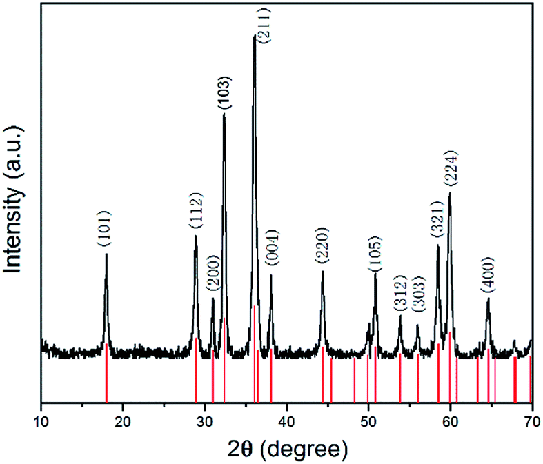 | ||
| Fig. 1 XRD pattern of Mn3O4 hollow microspheres. | ||
The morphology of the Mn3O4 product was investigated by FE-SEM and TEM. The typical SEM image of the Mn3O4 product shown in Fig. 2a displays that the crystals are formed in large scale with good dispersion and uniform diameter of about 500 nm. Moreover, observing from some broken microspheres shown in the partial enlarged detail in Fig. 2b, it is evident that these Mn3O4 microspheres are in hollow structure. Furthermore, the Mn3O4 microspheres were characterized with TEM to examine their fine structures. Fig. 2c shows that the Mn3O4 microspheres present a clear hollow structure with loose shell. A low magnification TEM image of the Mn3O4 hollow sphere shell is shown in Fig. 2d, which manifest that Mn3O4 nanocrystals were partially aggregated together. Measurement of about 100 nanocrystals from more HR-TEM images indicates that most nanocrystal sizes range from 7 to 15 nm, which is concordant with the value obtained from the XRD measurement. Also, there are some defects and vacancies on the surface of the sphere. Thus, it appears to be unsmooth. The vacancies and defects are beneficial to the Li-ion transport and redox reaction, which can improve the electrochemical performance of Mn3O4 as the lithium-ion battery material to some extent.11 As high-resolution transmission electron microscopy (HR-TEM) image of the Mn3O4 nanoparticles is shown in Fig. 2e, the lattice fringes exhibited different crystal planes, which can be identified in (103), (112), (211) and (200) planes with matching d-spacing of 0.2784, 0.3084, 0.2495 and 0.2910 nm, respectively. Fig. 2f is ring pattern of selected-area electron diffraction (SAED), the rings matched well with (101), (112), (103), (211), (220), (105), (224) planes, as reference to the JCPDS database (card of 27-0734) further demonstrate the tetragonal structure of Mn3O4 nanoparticles.
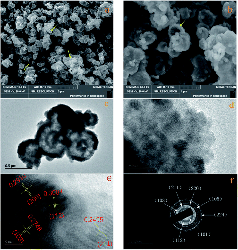 | ||
| Fig. 2 (a) Representative FE-SEM images of Mn3O4 and (b) FE-SEM image of partial enlarged detail (c) TEM image of Mn3O4; (d) TEM image of partial enlarged detail; (e) HR-TEM image of partial enlarged detail; (f) SAED image of Mn3O4. | ||
The specific surface area and pore size distribution of the synthesized Mn3O4 hollow microspheres were further investigated by N2 adsorption–desorption measurements. The adsorption isotherms profiles are displayed in Fig. 3. It shows that Mn3O4 hollow microspheres have a type isotherm of IV adsorption–desorption curve with a capillary condensation step and hysteresis loop which is characteristic of mesoporous materials. The BET surface area of the Mn3O4 sample is measured to be 87.1 m2 g−1 and a total pore volume of 0.2030 cm3 g−1, much higher than the previous reports. For example, the nanotube Mn3O4 present BET surface area about 48.83 m2 g−1 and a total pore volume of 0.08 cm3 g−1,13 the mesoporous Mn3O4 has a total pore volume of 0.150 cm3 g−1.34 The pore-size distribution curve (the inset in Fig. 4), obtained by the Barrette–Joynere–Halenda (BJH) method, shows the pore size distribution located around at 5 nm. From the TEM photos in Fig. 2, such pores were formed mainly by the stacking of nanoparticles. The narrow pore size distribution and big volume will contribute much to the effective transport and storage of ion at the interface of electrode/electrolyte, which shows the tremendous potential applications in LIBs, sensors and electrochemical super capacitors.
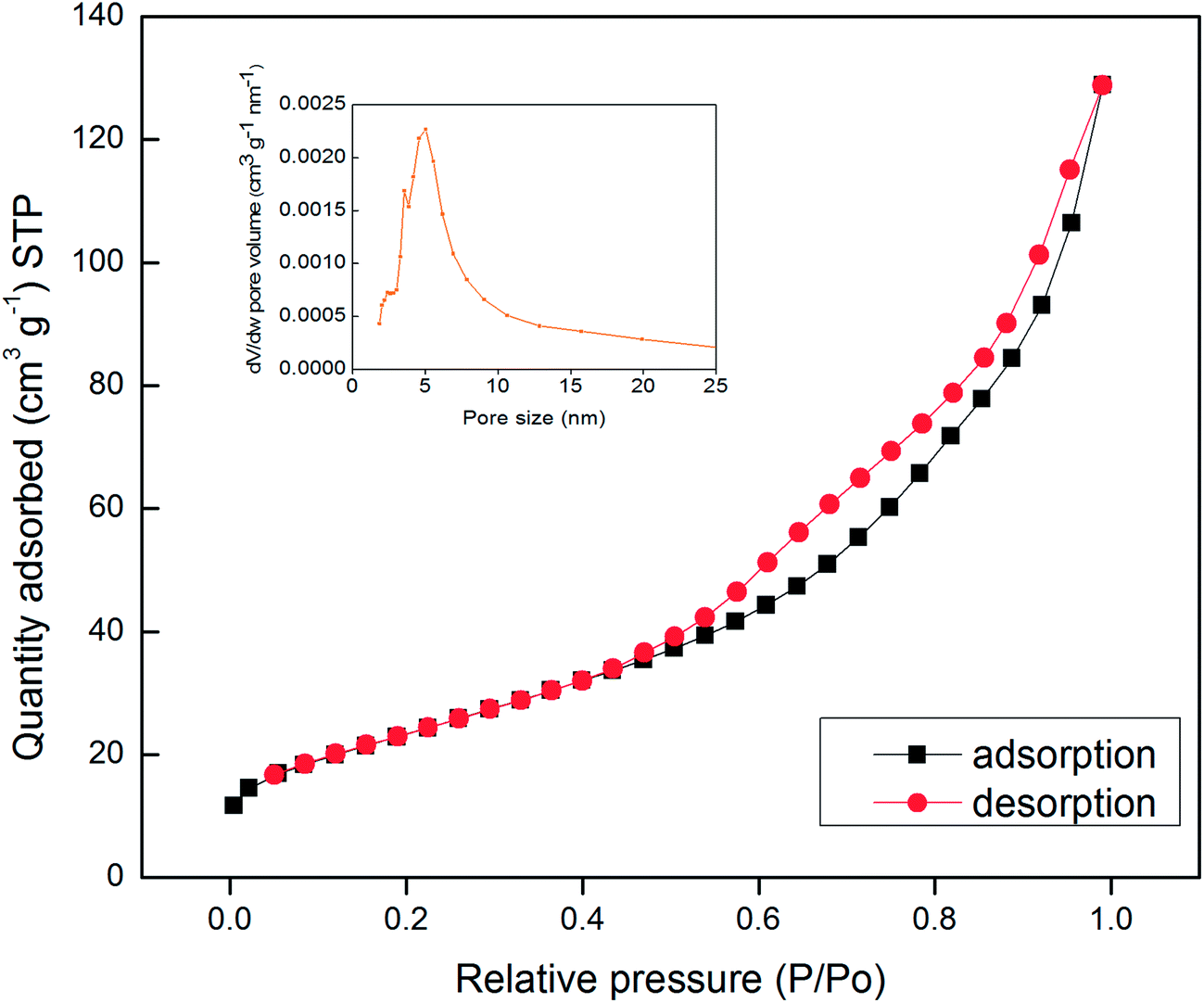 | ||
| Fig. 3 N2 adsorption isotherms and pore size distribution (insets) of Mn3O4 hollow microspheres. | ||
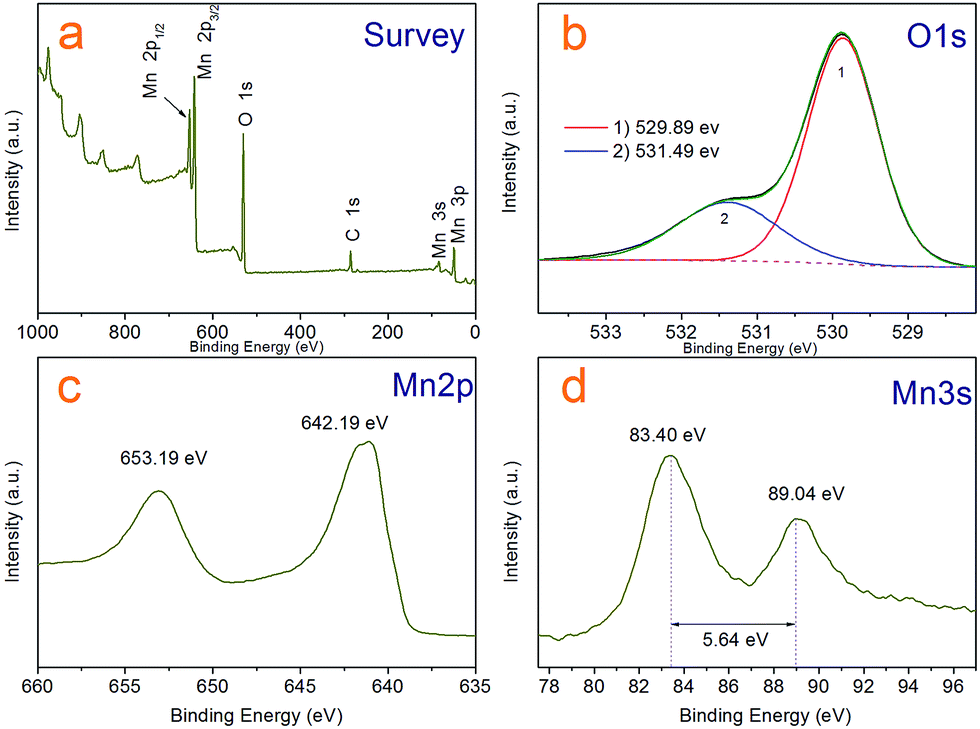 | ||
| Fig. 4 XPS spectra of the Mn3O4 hollow microspheres (a) survey scan, (b) O 1s, (c) Mn 2p (d) Mn 3s spectra. | ||
Although it is easy to see the hollow sphere product is pure Mn3O4 with hausmannite crystal structure from the XRD analysis and has clean and neat crystal faces from HR-TEM photos, we further characterized the sample by X-ray photoelectron spectroscopy (XPS) and analysed with liquid-phase micro extraction high performance liquid chromatography (LPME-HPLC) analysis procedure, to investigate if there is chloride pyridine composition remnant on the surface or wrapped inside the Mn3O4 nanocrystals. Fig. 4a shows a typical over XPS spectra of the Mn3O4 hollow microspheres, suggesting that the hollow microspheres test samples are composed of Mn 2p, 3s, 3p, O 1s and 2s, respectively, as well as a weaker C 1s peak at 284.8 eV always come from environmental carbon pollution used for the XPS curve correction. It is clear that N and Cl not detected in the curve, which substantiates almost no existence of chloropyridine components in surface of hollow spheres after washing process. Fig. 4c depicts the XPS spectrum of Mn 2p, where two peaks located at 642.19 eV and 653.19 eV can be respectively attributed to Mn 2p3/2 and Mn 2p1/2 levels. In the Mn 3s spectra (Fig. 4d), two peaks at 83.40 eV and 89.04 eV with a separation of 5.64 eV were observed, which agree well with that of reported for Mn3O4.35,36 As for the O 1s spectra shown in Fig. 4b, the asymmetric peak was obviously superposed by two peaks a main at 529.89 eV and weaker 531.49 eV one, which could be attributed to lattice oxygen (Olatt) and adsorbed oxygen (Oads), respectively.37 Adsorbed oxygen (Oads) can be associated with many kinds of species including low coordination situation, oxygen-containing surface contamination and surface chemisorbed oxygen. A higher ratio of Oads/Olatt (in our work is 0.4) could indicate a larger amount of chemisorbed oxygen species,38 which could explain that the as-prepared Mn3O4 hollow microspheres have a good interfacial activity.
In the LPME-HPLC analysis procedure, 0.1 g as-synthesis Mn3O4 sample dissolved in hydrochloric acid, and then the transparent solution was transferred into a 10 mL volumetric flask and diluted with purified water. 0.5 mL toluene was added to extract the organic compounds for analysing. The result showed that the residue of TECP was lower than 2.0 × 10⁻⁷ g in every one gram Mn3O4 sample and other chloride pyridine compositions were not detected.
3.2 Reaction mechanism and formation processes of hollow microspheres
To study the reaction mechanism and formation process of Mn3O4 hollow microspheres, the source material and intermediates were tested by XRD and SEM. The intermediate samples were taken 4 hours after NH4Ac solution were added dropwise at the temperature of 40 °C. Fig. 5a shows the XRD pattern of the metallic manganese source, which suggests that the source is pure Mn (JCPDS card of 32-0637, space group of I![[4 with combining macron]](https://www.rsc.org/images/entities/char_0034_0304.gif) 3m, a = 8.912, b = 8.912, c = 8.912). Fig. 5b shows the XRD pattern of the intermediates, which indicates that the intermediate has a Mn2(OH)3Cl crystal structure (JCPDS card 25-1158 space group pnam, a0 = 6.490, b0 = 9.52, c0 = 7.12). Fig. 5c shows the XRD pattern of final product Mn3O4. Based on the test results, the possible reaction mechanism of the first reaction step for obtaining TECP is described as follows.
3m, a = 8.912, b = 8.912, c = 8.912). Fig. 5b shows the XRD pattern of the intermediates, which indicates that the intermediate has a Mn2(OH)3Cl crystal structure (JCPDS card 25-1158 space group pnam, a0 = 6.490, b0 = 9.52, c0 = 7.12). Fig. 5c shows the XRD pattern of final product Mn3O4. Based on the test results, the possible reaction mechanism of the first reaction step for obtaining TECP is described as follows.| 2NH4+ + Mn → Mn(NH3)22+ + 2H˙ | (1) |
 | (2) |
| 2Cl˙ + Mn → Mn2+ + 2Cl− | (3) |
| 2Mn(NH3)22+ + 3H2O + Cl− → Mn2(OH)3Cl + 4NH4+ | (4) |
| 2H˙ → H2↑ | (5) |
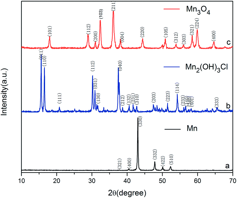 | ||
| Fig. 5 XRD pattern of (a) Mn; (b) Mn2(OH)3Cl; (c) Mn3O4. | ||
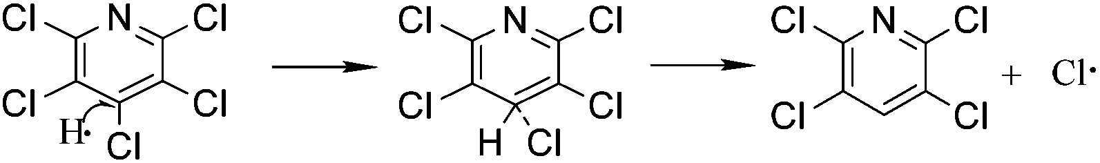
In reaction (1), catalyst NH4+ attaches on the surface of metallic Mn as a hydrogen carrier, where electron transferred from Mn (0) to NH4+ and reactive hydrogen and Mn(NH3)22+ generated. Then, Mn2+ could easily transfer from the surface of manganese powder into the solution in the form of Mn(NH3)22+ complexes, which is very important for the exposure of intimal Mn. As in reaction (2) and (3), the reactive hydrogen replaces p-Cl from PCP selectively, which is a typical hydrodechlorination by SN2 reaction process. At the meantime, substituted Cl gains another electron on the surface of metallic Mn and turned to Cl−1. Unavoidably, reactive hydrogens can easily combine to H2 as shown in reaction (5). Mn(NH3)22+ will hydrolyse into Mn2(OH)3Cl crystal as shown in reaction (4). Consequently, by using manganese powder as reducing agent, water as the hydrogen donor, NH4Ac as catalyst, alcohol as solvent and in an eco-friendly temperature of 40 °C, the yield and selectivity of TECP achieved up to 99.2% and 99.5%, respectively. As the pH value adjusted to 8.0 with NH3 H2O solution, all the Mn2+ transformed into Mn(OH)2 white precipitation. When the air flowed in, its colour apparently turned to brown quickly, which is the specific phenomenon of Mn(OH)2 out of all the manganese compounds.39 Mn(OH)2 will then dehydrate and generate Mn3O4. The reactions can be expressed as eqn (6)–(8).
| Mn2(OH)3Cl + NH3·H2O → 2Mn(OH)2 + NH4Cl | (6) |
| Mn(NH3)22+ + 2H2O → Mn(OH)2 + 2NH4+ | (7) |
| 6Mn(OH)2 + O2 → 2Mn3O4 + 6H2O | (8) |
To explain formation processes of hollow microspheres clearly, a plausible conjecture involving bubble-templating process was described in Scheme 1, where the by produced H2 plays the role of bubble templates. Actually, the gas bubble-templating method has been proved to be a facile process to fabricate hollow microspheres of inorganic materials, such as Fe,40 ZnO,41 ZnSe,42 CoOOH,43 CaCO3 (ref. 44) and Cu2xSeyS1y/rGO.45 As illustrated in Scheme 1, a certain concentration of H2 was generated by reaction (5) and formed sub-microbubbles. At the same time, a large amount of Mn2(OH)3Cl nuclei was produced in solution through the relatively low nucleation process by reaction (4), leading to a relatively high local concentration of Mn2(OH)3Cl. Thus, it inevitably resulted in Mn2(OH)3Cl nuclei diffusing to the gas–liquid interfaces between H2 bubbles and liquid solution. Then these Mn2(OH)3Cl nuclei grow into small size nanocrystals with the dispersion effect of ethyl alcohol. Additionally, small size H2 bubbles come into collisions in the dispersion system and coagulate to generate bigger H2 bubbles, while the Mn2(OH)3Cl nanocrystals on the surface of bubbles assembled into hollow microspheres. Other Mn2(OH)3Cl nanocrystals may also accumulate on the surface, forming the hollow sphere Mn2(OH)3Cl with a thick shell, which is confirmed by the SEM photo of Mn2(OH)3Cl with hollow structure as shown in Scheme 1. Driven by reaction (6)–(8), these nanocrystals generated smaller-volume Mn3O4 nanocrystals and left some space or pores between nanocrystals in the shell, forming as-prepared Mn3O4 hollow microspheres with macro- and mesoporous structures.
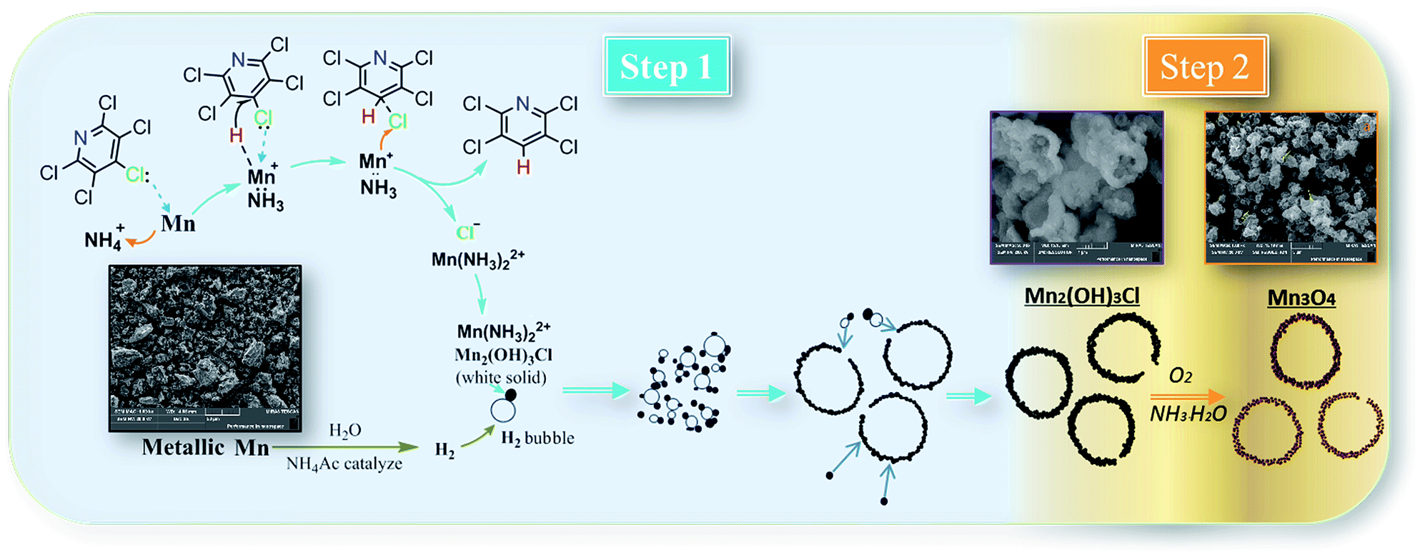 | ||
| Scheme 1 Possible mechanism for hydrodechlorination reaction process and formation processes of hollow microspheres. | ||
As a summary, two products 2,3,5,6-tetrachloropyridine and Mn3O4 hollow microspheres material were prepared in one pot via two simple steps with Mn, water, ethyl alcohol and air as inexpensive, non-toxic reductive agent, hydrogen source, solvent and oxidizing agent, respectively. With several advantages, including low temperature, low corrosion to equipment, good atom economy, organic-free template, low-cost, high conversion rate and selectivity, this hollow Mn3O4 microspheres preparation method was much better than those were previously reported. For example, Jian reported a method based on an in situ gas blowing mechanism in single aerosol droplets, in which Mn(NO3)2, sucrose and H2O2 used as raw material to synthesize hollow Mn3O4 microspheres.17 Yue used carbon nanospheres (CNSs) as a template and reagent to reduce KMnO4 into hollow MnO2 nanospheres, and then the hollow MnO2 nanospheres were reduced under an atmosphere of H2/Ar into hollow Mn3O4 microspheres at 280 °C for 3 h.46 Sun reported a surface-layer-adsorption and calcination (SLA-C) method for the fabrication of hollow Mn3O4 microspheres by templating carbonaceous microspheres.47 Thus, it can be considered as a facile and green synthesis technology, as is summarized in reaction (9).
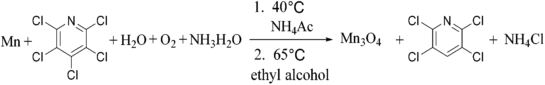 | (9) |
3.3 Electrochemical performance
The electrochemical properties of the as-synthesized Mn3O4 hollow microspheres were evaluated by cyclic voltammetry (CV) conducted in the range of 0.01 and 3.00 V at a scan rate of 0.40 mV s−1, which is shown in Fig. 6. During the first cathodic process, there was a broad weak peak located at 1.10 V which disappeared afterwards. This peak can mainly be attributed to the formation of a solid electrolyte interphase (SEI) layer because of the decomposition of the electrolyte and formation of solid-state interface of the Mn3O4 hollow microspheres. The intensive peak which appeared in the low potential is ascribed to the reduction of Mn3O4 into Mn0 accompanied by the generation of Li2O. In the following anodic process, it can be observed at around 1.3 V that Mn0 is oxidized to Mn3O4 and Li2O is decomposed in the meantime. In the following cycles, the reduction peak shifted to a higher voltage about 0.3 V, which is primarily due to an irreversible structure change related to the lithium insertion. After the second cycle, the CV curves demonstrate good reversibility and stability of the Mn3O4 hollow microspheres.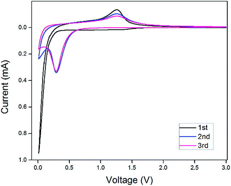 | ||
| Fig. 6 Cyclic voltammetry (CV) curves of the 1st 2nd and 3rd cycles for the Mn3O4 hollow microspheres at a scan rate of 0.40 mV s−1 between 0.01 and 3.00 V. | ||
Fig. 7a shows the cycling stability curve of the Mn3O4 hollow microspheres, examined by charging/discharging between 3.00 and 0.01 V at a current density of 200 mA g−1 over 240 cycles. The electrode has a large initial discharge capacity of about 1577.8 mA h g−1. However, the coulombic efficiency for the first cycle was 46% with the first charge capacity of 720.48 mA h g−1, then the discharge capacity gradually dropped to 448.2 mA h g−1 at the 38th cycle, while the coulombic efficiency increased to 93% sharply at the second cycle, then gradually increased to and maintained at between 95–100% in the following several hundred cycles (Fig. 7b). The capacities of Mn3O4 exhibited a rising trend from the 39th cycle, and the electrode retains an average reversible capacity of 637.2 mA h g−1 during the 130th cycle to the 240th cycle. The Mn3O4 hollow microspheres electrode still retains a reversible capacity of 646.9 mA h g−1 after total around 240th cycles. Such a rising trend of capacity between the 38th–130th is normally observed in transition metal oxides and is well-documented in literatures.1,48–51 It is considered to be attributed to the reversible growth process of a polymeric gel-like film resulting from kinetically activated electrolyte degradation. In terms of discharge capacity and cycling stability, our electrode performs better than some previously reported Mn3O4 electrode.
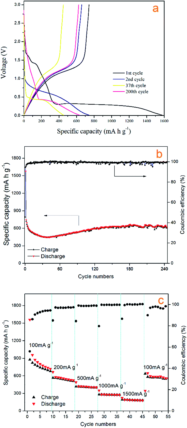 | ||
| Fig. 7 (a) The 1st, 2nd, 37th and 200th voltage profiles of the Mn3O4 electrode between 0.01 and 3.00 V at a current density of 200 mA g−1. (b) Cycle performance and coulombic efficiency versus cycle number of Mn3O4 hollow spheres at a current density of 200 mA g−1. (c) Rate capabilities with increasing current density. | ||
The charge/discharge profiles of the hollow Mn3O4 microspheres in the 1st, 2nd, 37th, and 200th cycles for the Mn3O4 hollow microspheres electrode cycled between 3.00 and 0.01 V at a current density of 200 mA g−1 are shown in Fig. 6a. In the first discharge curve, it is observed a sloping voltage from 2.00 to 0.35 V is attributed to the generation of solid-electrolyte interphase (SEI) film and the reduction of Mn3+ to Mn2+. The well-defined voltage plateau at 0.35 V is related to the main reduction of Mn2+ to Mn0. In the charge curve, the Mn3O4 hollow microspheres electrode shows a gentle incline in the voltage range between 1.0 and 1.5 V, which is associated with the oxidation from Mn0 to Mn2+/Mn3+. In comply with the CV results, in the second cycle the lithiation plateau moves to a higher voltage of about 0.65 V and the sloping voltage rapidly decreased from 1.75 V to 1.00 V which are attributed to an irreversible capacity loss of 54%, resulted from the phase transformation in the first cycle. As the cycle times increase from 2nd cycle to 37th cycle, the lithiation plateau continue decreasing to a lower voltage of about 0.5 V, which is attributed to the continuing phase transformation occurred in the conversion process. The lithiation plateau of the 200th cycle hardly changed compared with the 37th cycle, but the voltage decrease from 2.00 V to 0.50 V is much slower, which contributes a lot to the increase of the reversible capacity, and it also confirms the dominant influence on Mn3O4/Li cell capacity from the reversible growth of polymeric gel-like film.
The perfect electrochemical performance of the synthesized Mn3O4 hollow microspheres could be associated with the big specific surface area and the big total pore volume of the macro- and mesoporous. The porous sponge structure could improve the efficient utilization of active material and allow lithium ions to transfer easily in and out. The unique structure is also able to accommodate the strain by volume change during conversion process and maintain the integrity in the reversible growth process of polymeric gel-like film.
We also investigated the rate capability of Mn3O4 hollow microspheres at increased stepwise current densities from 100 mA g−1 to 1500 mA g−1 between 0.01 and 3.00 V with each current density tested for 8 cycles (Fig. 7c). At current density of 100 mA g−1, it delivered an initial capacity of about 955 mA h g−1, then reduced to 718 mA h g−1 gradually. Even at 1500 mA g−1 the Mn3O4 hollow microspheres can still deliver a specific capacity of nearly 200 mA h g−1. When the test current density returns to 100 mA g−1 again, the capacity recovered to 645 mA h g−1, which was close to the capacity at the initial rate of 100 mA g−1, indicating a good reversibility of the Mn3O4 hollow microspheres. Thus, as-prepared Mn3O4 hollow microspheres showed good electrochemical properties and huge application potential in high capacity LIB anode materials.
4. Conclusions
In summary, a new facile and green route for the preparation of Mn3O4 hollow microspheres and 2,3,5,6-tetrachloropyridine in one pot via two simple steps was developed using Mn, water, ethyl alcohol and air as inexpensive non-toxic reductive agent, hydrogen source, solvent and oxidizing agent, respectively. Mn3O4 hollow microspheres was made by H2 gas bubble-templating method presenting a high specific surface area (87.1 m2 g−1) and a big a total pore volume (0.2030 cm3 g−1). The Mn3O4 hollow microspheres electrode shows a good electrochemical performance with a reversible specific capacity of 646.9 mA h g−1 at a current density of 200 mA g−1 after 240 cycles. In addition, the yield and selectivity of 2,3,5,6-tetrachloropyridine achieved up to 99.2% and 99.5%, respectively. Above all, the whole process has several advantages, including low temperature, low corrosion to equipment, good atom economy, surfactant and/or solid free template, low-cost, high conversion rate and selectivity and short reaction process. The 2,3,5,6-tetrachloropyridine will significantly reduce the production costs of Mn3O4 product. The strategy of Mn3O4 preparation, substituting zinc with manganese can possibly be extended to other organic reductions using zinc dust as reducing agent.Acknowledgements
This work was financially supported by National Science and Technology Support Plan of China (2015BAB17B01) National Natural Science Foundation of China (21376273) and the Hunan Provincial Science and Technology Plan Project, China (No. 2016TP1007).Notes and references
- Q. Hao, J. Wang and C. Xu, J. Mater. Chem. A, 2014, 2, 87–93 CAS.
- I. Nam, N. D. Kim, G.-P. Kim, J. Park and J. Yi, J. Power Sources, 2013, 244, 56–62 CrossRef CAS.
- J. Wang, N. Du, H. Wu, H. Zhang, J. Yu and D. Yang, J. Power Sources, 2013, 222, 32–37 CrossRef CAS.
- J. Gao, M. A. Lowe and H. D. Abruna, Chem. Mater., 2011, 23, 3223–3227 CrossRef CAS.
- G. Wang, B. Huang, Z. Lou, Z. Wang, X. Qin, X. Zhang and Y. Dai, Appl. Catal., B, 2016, 180, 6–12 CrossRef CAS.
- Y. Li, J. Qu, F. Gao, S. Lv, L. Shi, C. He and J. Sun, Appl. Catal., B, 2015, 162, 268–274 CrossRef CAS.
- W. B. S. Machini and M. F. S. Teixeira, Electroanalysis, 2014, 26, 2301 CrossRef CAS.
- L. C. Dong, Y. B. Zhong, S. Zhe, T. Y. Zheng and H. Wang, RSC Adv., 2016, 6, 21037–21042 RSC.
- I. Ryu, G. Kim, D. Park and S. Yim, J. Power Sources, 2015, 297, 98–104 CrossRef CAS.
- X. W. Lou, L. A. Archer and Z. Yang, Adv. Mater., 2008, 20, 3987–4019 CrossRef CAS.
- X. Lai, J. E. Halpert and D. Wang, Energy Environ. Sci., 2012, 5, 5604–5618 CAS.
- Z. Wang, L. Zhou and X. W. Lou, Adv. Mater., 2012, 24, 1903–1911 CrossRef CAS PubMed.
- Z. Bai, N. Fan, Z. Ju, C. Guo, Y. Qian, B. Tang and S. Xiong, J. Mater. Chem. A, 2013, 1, 10985–10990 CAS.
- D. Pasero, N. Reeves and A. R. West, J. Power Sources, 2005, 141, 156–158 CrossRef CAS.
- C. Wang, L. Yin, D. Xiang and Y. Qi, ACS Appl. Mater. Interfaces, 2012, 4, 1636–1642 CAS.
- D. P. Dubal and R. Holze, RSC Adv., 2012, 2, 12096–12100 RSC.
- G. Jian, Y. Xu, L.-C. Lai, C. Wang and M. R. Zachariah, J. Mater. Chem. A, 2014, 2, 4627–4632 CAS.
- N. Lavoie, P. R. L. Malenfant, F. M. Courtel, Y. Abu-Lebdeh and I. J. Davidson, J. Power Sources, 2012, 213, 249–254 CrossRef CAS.
- S. Liu, Y. Wang, J. Jiang and Z. Jin, Green Chem., 2009, 11, 1397–1400 RSC.
- J. Kroemer, C. Kirkpatrick, B. Maricle, R. Gawrych, M. D. Mosher and D. Kaufman, Tetrahedron Lett., 2006, 47, 6339–6341 CrossRef CAS.
- S. Suresh, Open Waste Manage. J., 2009, 2, 6–16 CrossRef CAS.
- H. Chen and S. Liu, Chem. Eng. Sci., 2015, 138, 510–515 CrossRef CAS.
- G. N. Jovanovic, J. E. Atwater, P. Znidarsic-Plazl and I. Plazl, Chem. Eng. J., 2015, 274, 50–60 CrossRef CAS.
- Y.-h. Shih, M.-Y. Chen and Y.-F. Su, Appl. Catal., B, 2011, 105, 24–29 CrossRef CAS.
- C.-B. Wang and W.-x. Zhang, Environ. Sci. Technol., 1997, 31, 2154–2156 CrossRef CAS.
- A.-Y. Guan, C.-L. Liu, X.-F. Sun, Y. Xie and M.-A. Wang, Bioorg. Med. Chem., 2016, 24, 342–353 CrossRef CAS PubMed.
- R. H. Rigterink, US. Pat., 3, 244, 586, 1966.
- Y. Matsuzaki, WO. Pat., 2015012245A1, 2015.
- Z. Xiaomao, D. Huijuan and L. wei, CN. Pat., 102718700A, 2012.
- J. C. Yang, M. Li, Q. Wu, C. L. Liu and X. H. Chang, Bioorg. Med. Chem., 2015, 24, 383–390 CrossRef PubMed.
- F. H. Murphy, US. Pat. 470 3123 A, 1987.
- O. Zaberca, A. Gillorin, B. Durand and J. Y. Chane-Ching, J. Mater. Chem., 2011, 21, 6483–6486 RSC.
- Y. Zhao, Z. Zhang and H. Dang, J. Phys. Chem. B, 2003, 107, 7574–7576 CrossRef CAS.
- F. Yang, M. Zhao, Q. Sun and Y. Qiao, RSC Adv., 2015, 5, 9843–9847 RSC.
- G. Zhao, J. Li, W. Zhu, X. Ma, Y. Guo, Z. Liu and Y. Yang, New J. Chem., 2016, 40, 10108–10115 RSC .
- J. W. Lee, A. S. Hall, J.-D. Kim and T. E. Mallouk, Chem. Mater., 2012, 24, 1158–1164 CrossRef CAS.
- J. Li, X. Liang, S. Xu and J. Hao, Appl. Catal., B, 2009, 90, 307–312 CrossRef CAS.
- Y. Wang, A.-P. Jia, M.-F. Luo and J.-Q. Lu, Appl. Catal., B, 2015, 165, 477–486 CrossRef CAS.
- M. Fang, X. Tan, M. Liu, S. Kang, X. Hu and L. Zhang, CrystEngComm, 2011, 13, 4915–4920 RSC.
- G. X. Tong, J. G. Guan, Z. D. Xiao, F. Z. Mou, W. Wang and G. Q. Yan, Chem. Mater., 2008, 20, 3535–3539 CrossRef CAS.
- C. Yan and D. Xue, J. Alloys Compd., 2007, 431, 241–245 CrossRef CAS.
- Q. Peng, Y. Dong and Y. Li, Angew. Chem., Int. Ed., 2003, 42, 3027–3030 CrossRef CAS PubMed.
- J. Yang and T. Sasaki, Chem. Mater., 2008, 20, 2049–2056 CrossRef CAS.
- G. Hadiko, Y. S. Han, M. Fuji and M. Takahashi, Mater. Lett., 2005, 59, 2519–2522 CrossRef CAS.
- W. L. Li, H. Y. Zou, J. Lan, Q. Wang, Y. F. Li and C. Z. Huang, RSC Adv., 2015, 5, 91206–91212 RSC.
- J. Yue, X. Gu, L. Chen, N. Wang, X. Jiang, H. Xu, J. Yang and Y. Qian, J. Mater. Chem. A, 2014, 2, 17421–17426 CAS.
- X. Sun, J. Liu and Y. Li, Chem.–Eur. J., 2006, 12, 2039–2047 CrossRef CAS PubMed.
- S. Laruelle, S. Grugeon, P. Poizot, M. Dolle, L. Dupont and J. M. Tarascon, J. Electrochem. Soc., 2002, 149, A627–A634 CrossRef CAS.
- G. Zhou, D.-W. Wang, F. Li, L. Zhang, N. Li, Z.-S. Wu, L. Wen, G. Q. Lu and H.-M. Cheng, Chem. Mater., 2010, 22, 5306–5313 CrossRef CAS.
- S. Grugeon, S. Laruelle, L. Dupont and J. M. Tarascon, Solid State Sci., 2003, 5, 895–904 CrossRef CAS.
- J.-S. Do and C.-H. Weng, J. Power Sources, 2005, 146, 482–486 CrossRef CAS.
| This journal is © The Royal Society of Chemistry 2017 |