
Facile loading of thin-film surface-anchored metal-organic frameworks with Lewis-base guest molecules†
Nicolò
Baroni
a,
Andrey
Turshatov
 a,
Michael
Oldenburg
a,
Dmitry
Busko
a,
Michael
Adams
a,
Ritesh
Haldar
b,
Alexander
Welle
b,
Engelbert
Redel
b,
Christof
Wöll
b,
Bryce S.
Richards
ac and
Ian A.
Howard
*ac
a,
Michael
Oldenburg
a,
Dmitry
Busko
a,
Michael
Adams
a,
Ritesh
Haldar
b,
Alexander
Welle
b,
Engelbert
Redel
b,
Christof
Wöll
b,
Bryce S.
Richards
ac and
Ian A.
Howard
*ac
aInstitute of Microstructure Technology (IMT), Karlsruhe Institute of Technology, Hermann-von-Helmholtz-Platz 1, 76344 Eggenstein-Leopoldshafen, Germany. E-mail: ian.howard@kit.edu
bInstitute of Functional Interfaces (IFG), Karlsruhe Institute of Technology, Hermann-von-Helmholtz-Platz 1, 76344 Eggenstein-Leopoldshafen, Germany
cLight Technology Institute (LTI), Karlsruhe Institute of Technology, Engesserstrasse 13, 76131, Karlsruhe, Germany
First published on 31st May 2017
Abstract
In this work, we demonstrate how dye molecules with lone electron pairs, Lewis-base functionality, can be loaded into a surface anchored metal-organic framework system (SURMOF-2) directly from ethanolic solution without the need for any activation procedure. The dye loading profile throughout the SURMOF-2 layer is confirmed by time-of-flight secondary ion mass spectrometry (ToF-SIMS). The loaded porphyrin dyes show signs of aggregation, characterized by broadening of the absorption spectra and changes in the emission spectra and lifetimes. The triplet exciton dynamics of the Pd and Pt metallated porphyrin after inclusion in the SURMOF are characterized by a red-shifted phosphorescence (around 800 nm peak) with a lifetime in the range of 50 μs. The monomer-like emission (620 nm) has a lifetime of less than 3 μs. Similarly, the singlet dynamics of the Zn metallated porphyrin show no sign of residual monomer emission in the SURMOF. In summary, these results show a route through which guest molecules can be easily loaded into SURMOFs. The loading is achieved with a printing-compatible technique and it can lead to guest molecule concentrations that are sufficiently high that there are strong interactions between guest molecules. This opens interesting avenues towards printing guest molecules onto SURMOFs to selectively bestow new properties to patterned loaded areas of the SURMOF.
Introduction
Metal–organic frameworks (MOFs) are a class of crystalline coordination polymers in which metal centers are linked by covalently-bonded organic ligands. This material class is inherently highly versatile and there exists a vast library of known structures that is continuingly expanding with new ligands to realize different functional and structural properties.1 One particularly important feature of MOFs is their porosity. Open channels through the MOFs' three dimensional crystalline structures allow for the transport of molecules from the environment to interior sites of the MOF with which they can interact. These material features have been capitalized upon for a variety of applications; in the first years gas storage and catalysis2,3 were the most important technologically relevant fields. Subsequently, the use of these channels to selectively absorb guest molecules has been exploited for purposes of filtration in the liquid phase,4–7 and also to bestow novel properties to the MOF.8–10The inclusion of guest molecules in MOFs recently acquired broad new relevance with the demonstration that guest molecules can be loaded into the MOF voids to change the fundamental properties of these porous, crystalline solids.11,12 For example, the inclusion of ferrocene substantially enhanced electrochemical conductivity13 and Talin and coworkers demonstrated that the electrical conductivity of an initially-insulating MOF could be increased by over six orders of magnitude with the introduction of the guest molecule 7,7,8,8-tetracyanoquinodimethane (TCNQ).14 The concept that guest molecules can be used to bestow new functionality to MOF materials has been applied to design materials with high Seebeck coefficients for thermoelectric applications.15,16 There are also precedents for the inclusion of chromophore guests affording optoelectronic functionality MOFs. For example, An et al. demonstrated that lanthanide ions can be added as guests to a MOF to bestow a variety of emissive properties,17 a strategy that has been extended to achieve white-light-emitting MOFs,18,19 and for Eu-based compounds the MOF organic linkers have been shown to act as antennas to transfer optical excitations to embedded dyes.20 Yu and coworkers revealed that two-photon lasing, which is visible lasing upon near-infrared (NIR) optical excitation, can be achieved in MOF crystals loaded with hemicyanine chromophores as guests.21 In this case, not only did the MOF crystal provide facets of sufficient quality to make an optical resonator for lasing, but also the inclusion of the hemicyanine dye in the MOF suppressed the aggregation-induced quenching that often limits lasing of organic chromophores at high concentrations in the solid state. Another example of guests bestowing optical properties on MOFs involves loading dipolar chromophores into MOF channels to form a non-centrosymmetric bulk material exhibiting significant second order optical properties such as second harmonic generation.22 Also, precursors guest molecules could be loaded and reacted within a MOF framework to introduce photocatalytic centers.23
In terms of realizing practical devices, it is often desirable to grow MOFs in a thin-film configuration on solid substrates. Although it is possible to process MOF powders into thin amorphous films,18 an alternative is the robust layer-by-layer deposition technique that allows certain MOFs to be grown directly on a substrate.24,25 The surface-anchored metal-organic frameworks (SURMOFs) resulting from this liquid-phase epitaxy scheme exhibit high degrees of crystalline order and orientation with relation to the substrate and are excellent candidates for studying the loading of MOFs with guest molecules in a quantitative fashion.26 However, a critical consideration for guest loading is how the guest molecules interact with the SURMOF, including interactions with open coordination centers on the MOF metal centers and dispersion forces with the ligands.27,28 When guest molecules are loaded from a solvent these interactions dictate whether the guest molecules will fill the SURMOF or whether preferential interaction with the solvent molecules or residual adsorbed water will hinder the loading of guest molecules.27,29
In this contribution we examine how chromophores can be loaded into the benchmark SURMOF-2 sheet-like structure based on 1,4-benzenedicarboxylate (BDC) linkers and Cu2+ or Zn2+ metal centers with the general formula M2(BDC)2. A wide variety of SURMOFs adopt the SURMOF-2 structure. They are based on linear dicarboxylic acid ligands connected through Zn2+ or Cu2+ paddle wheels, making – on a surface presenting OH anchoring sites – two-dimensional sheets standing perpendicular to the substrate and stacked closely to one-another in the out-of-plane direction.30 The metal centers in these structures have open coordination sites (OSCs) at which guest or solvent molecules that act as Lewis-bases – electron donors – can be weakly bound.29,31
In this work, we examine how dye molecules with and without lone electron pairs – such that Lewis-base functionality is exhibited or not – can be loaded into the SURMOF-2 system directly from ethanolic solution. Such a direct loading via drop-casting of the guest molecules is attractive from a viewpoint of processability, as it would allow facile printing of optoelectronic functionality onto a SURMOF substrate without the need for elevated temperature (all process steps occur at room temperature) or chlorinated solvents. We also characterize the photophysical properties of the chromophore guests within the SURMOF-2 structures. The porphyrin-based chromophores show strong signs of aggregation irrespective of whether their emission comes from a singlet (zinc-porphyrin) or triplet (palladium- and platinum-porphyrin) state. In all cases, the aggregation suggests that the dyes tend to interact with one another within this class of solid-state SURMOF host.
Results
Thin film SURMOF samples based on 1,4-benzenedicarboxylic acid linkers and either Zn2+ or Cu2+ metal centers were prepared using the layer-by-layer approach previously reported in the literature.32 We then loaded these optically transparent films with various porphyrin test dyes by depositing a droplet of a dye solution onto the substrate and allowing it to evaporate, as described below. The Zn and Cu-based SURMOFs exhibit identical loading behavior. However, the open d-shells in the Cu paddlewheels create fast non-radiative pathways such that no emission is observable from guest molecules loaded in the Cu-based SURMOFs.33 For this reason, we present the characterization of the loaded Zn-based SURMOFs in detail below but note that Cu-based SURMOFs can be loaded in an identical fashion.Fig. 1a shows the chemical structures of the dyes we attempted to load into the SURMOFs thin films. They are variously metallated porphyrins with and without carboxylic pendant groups. As described below, we find that the carboxylic functionality is crucial for allowing the dyes to be loaded; porphyrins with carboxylic groups can be loaded into the SURMOFs while the dyes without carboxylic acid groups cannot. In total five dyes were tested; they were metallated with either Zn, Pt, or Pd and for each of these metal centers a dye with and without carboxylic acid groups was tested. Without the carboxylic acid the dye structures were 2,3,7,8,12,13,17,18-octaethyl-21H,23H-porphine zinc(II) and 2,3,7,8,12,13,17,18-octaethyl-21H,23H-porphine palladium(II), whereas with the carboxylic pendant groups the dye structures for the Zn and Pt metal centers were meso-tetra (four-carboxyphenyl) porphine containing 4 carboxylic groups and the structure for the Pd metal center was 5,15-diphenyl-10,20-di(4-carboxyphenyl)porphine with only two carboxylic groups.
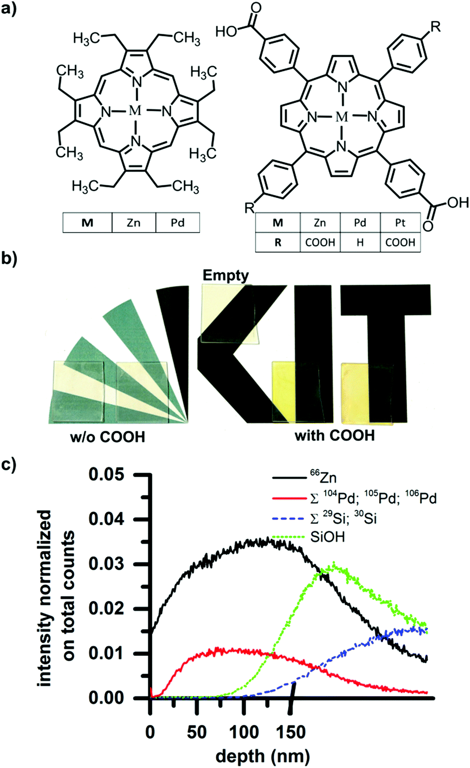 | ||
| Fig. 1 (a) Structures of the dyes used for loading. Those not containing pendant hydroxyl groups on the left and those containing pendant hydroxyl groups shown to the right. (b) Photograph of SURMOF films on glass before and after drop-casting and rinsing. After rinsing, colored films were only left for dyes containing hydroxyl groups, suggesting that these better penetrated the porous SURMOF film. (c) ToF-SIMS depth profile of the Pd-COOH dye in the SURMOF. 10 points binning. The Pd signal specific to the dye is absent at the surface (depth = 0 nm) but present through the rest of the SURMOF film, indicating that the COOH-containing dyes are absorbed throughout the SURMOF layer. The depth scale is stopped when we reached the interface between SURMOF and substrate (Zn signal decreases and the SiOH to rises) because the eroding rate on silicon oxide and silicon is much slower than the SURMOF. | ||
After the SURMOFs were prepared on glass substrates (2 cm × 2.5 cm), 1 ml of a 0.1 mM dye solution in ethanol was deposited onto each SURMOF and allowed to dry. After drying, the samples were washed under a flow of ethanol for 10 seconds to remove any dye adsorbed to the film surface. Immediately following this procedure, clear differences between the samples exposed to the carboxyl-containing dyes and the non-carboxyl-containing dyes were visible by eye. The carboxyl-containing dyes leave result in samples possessing a strong coloration, whereas the other dyes were completely washed away and the sample returned to the original transparency of the SURMOF. The photograph in Fig. 1b records: (i) the original transparency of a pristine SURMOF thin-film (labeled “empty”); as well as the colored films resulting from (ii) drop-casting carboxyl-containing dyes (after rinsing); and (iii) the again transparent samples resulting after drop-casting then washing the non-carboxyl containing dyes. This illustrates that whereas the dyes without carboxyl functionality form only a surface layer that is washed away, the dyes with carboxyl functionality also can penetrate into the porous structure of the SURMOF and are retained there even after the surface-coating is rinsed away. The X-ray diffraction patterns obtained before and after loading are unchanged, demonstrating that the loading does not affect the crystallinity of the sample (see Fig. S1 of the ESI,† for X-ray diffractograms before and after loading).
In order to examine the dye loading in more detail, the depth concentration profile of the dye loading can be ascertained by time-of-flight secondary ion mass spectrometry (ToF-SIMS). In a SURMOF loaded with the Pd metallated porphyrin, the depth profile of the dye within the sample can be traced by the Pd signal, while the Zn signal reports the thickness of the SURMOF layer. For the ToF-SIMS measurement, samples were prepared on silicon instead of glass to avoid charging during the process of ion bombardment. For dual beam depth profiling a 20 keV C60+ beam was used, fully interlaced with a 25 keV Bi3+ beam of 1.2 ns pulse width for mass spectrometry. The former beam was scanned over 500 × 500 μm2 (0.6 nA pulsed beam current), while the latter scanned a concentric field of view of 200 × 200 μm2, 64 × 64 pixel, 0.5 pA. The results (shown in Fig. 1c) illustrate that on the surface of the sample surface (t = 0 s) there is almost no signal from Pd (sum of 104Pd, 105Pd, and 106Pd), indicating that all the surface adsorbed dyes have been washed away. As the surface is eroded and the bulk of the film exposed, the Pd signal from the dye increases. This indicates that the dye was indeed captured within the SURMOF structure during the drop-casting process. The Pd signals and 66Zn signal of the dye and SURMOF respectively show the same trend until the SiOH then Si signals (sum of both weaker isotopes 29Si and 30Si) rise, indicating that the substrate has been reached. Thus, we can demonstrate that the dyes are incorporated throughout the entire thickness of the SURMOF film (measured to be 150 nm by profilometry).
Having established that carboxyl containing dyes can be easily loaded into the SURMOFs via drop-casting, we turn to investigating the photophysical properties of the dyes within the SURMOF matrix. Fig. 2 plots the optical absorbance spectra of the carboxyl-containing dyes in dilute solution (0.1 mM) compared to when loaded into the SURMOF matrix. In all cases the absorption spectrum of the dyes after loading into the SURMOF is significantly altered with respect to the solution spectrum. The Soret band broadens significantly with a clear red-shift being visible for the PdCOOH and ZnCOOH dyes and a broadening of the absorption spectrum of the PtCOOH. The in-plane X-ray diffraction data from the SURMOFs both before and after dye-loading exhibit the same typical diffraction pattern of the Zn-BDC SURMOF (see Fig. S1, ESI†). Thus, no shift in the structure of the SURMOF is induced via dye loading and the distance between adjacent SURMOF sheets remains at 0.6 nm, which is only slightly larger than the thickness of a single porphyrin molecule.34 This suggests that the porphyrin molecules can only aggregate by forming sheet-like structures of edge-on interacting molecules interdigitated with the SURMOF sheets; the formation of co-facial aggregates should be impossible as two molecules co-facially arranged should not fit within the 0.6 nm gap between the SURMOF sheets. Given the symmetry of the porphyrin molecules possessing two transition dipole moments in the molecular plane which are orthogonal to each other; this leads to both H- and J-type interactions between porphyrin dyes edge-on in a sheet,35vide infra. Thus, the broadened absorption spectra that we observe are consistent with both H- and J-type coupling of two-dimensional sheet or plate-like aggregates in the SURMOF.
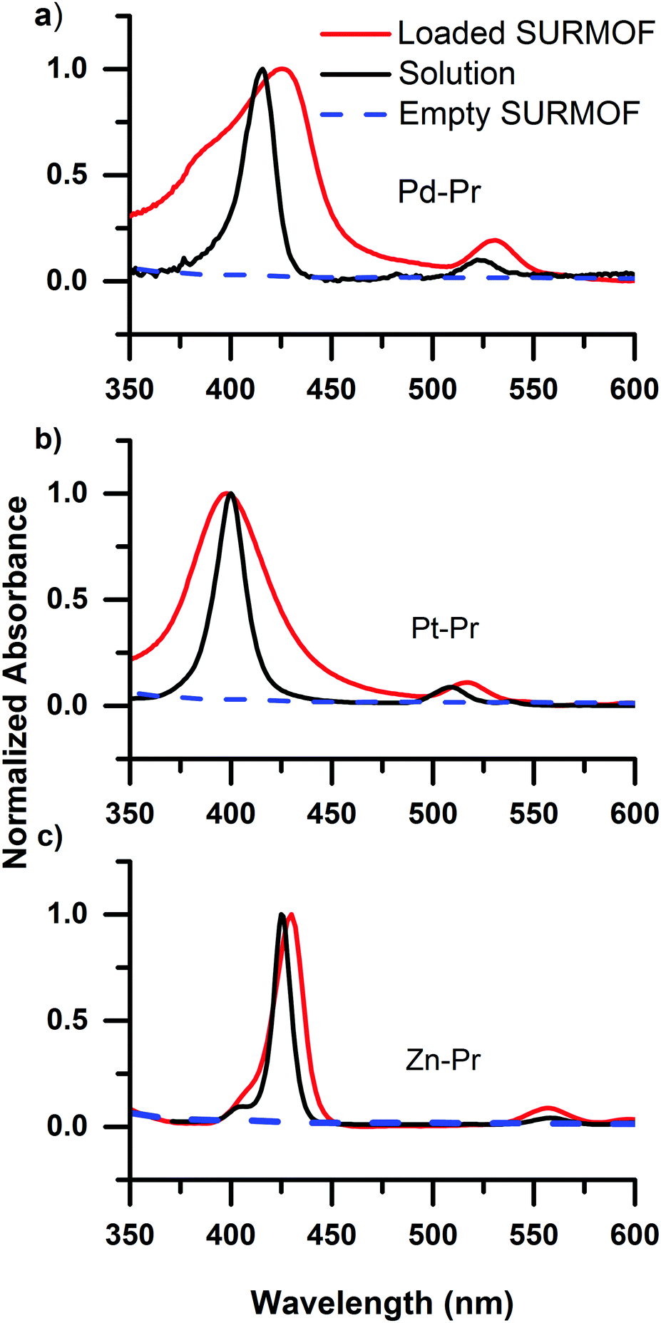 | ||
| Fig. 2 Comparison of the absorbance of the carboxyl-containing porphyrin dyes in 0.1 mM solution and loaded into a SURMOF. The dyes are metallated with (a) Pd, (b) Pt, and (c) Zn. The broadening of the absorption spectrum upon introduction as a guest molecule in the SURMOF is consistent with H- and J-type interactions within plate-like porphyrin aggregates formed in between the SURMOF sheets upon loading. | ||
Time-resolved emission of the dye@SURMOFs
Deeper insight into the porphyrin@SURMOF systems can be gained by examining their time-resolved luminescence and comparing the results to the excellent understanding of the photophysics of porphyrin systems available in the literature. The most salient points of this understanding are briefly reviewed in the following. The intersystem crossing rate for Pd and Pt metallated porphyrins is fast; the singlet population crosses to the triplet state with essentially unity yield meaning that the emission characteristics are determined by phosphorescence from the triplet state.36 This is not the case for the Zn metallated porphyrin wherein the intersystem crossing rate is slower than the radiative rate and the emission originates from the singlet state.36 Previous studies of interacting porphyrins have observed red-shifting and bi-exponential decay of the emission, both from the singlet37 and triplet states.38,39 When porphyrins metallated with Pt or Pd form aggregates, the triplet emission of the monomer around 650 nm is joined by a NIR emission from triplet aggregates that peaks at around 780 nm but extends to longer wavelengths.39 The NIR phosphorescence from the triplet aggregate present in solid-state solutions was found to have a lifetime in the range of 10 μs, with the lifetime of the phosphorescence of the monomer being quenched from several hundred microseconds (for PtOEP in solution)40,41 to less than 200 ns in the presence of the aggregates.38In Fig. 3, we show the emission dynamics of the Pd-Pr@SURMOF sample over a time-range of 500 μs measured with a streak camera. The sample was held under dynamic vacuum of <10−4 hPa and is excited by a quasi-CW (40 MHz) laser gated using an acousto-optic modulator to provide a square wave signal at 500 Hz. This provides 1 ms of excitation light from the laser followed by 1 ms of darkness. The samples measured within a week of synthesis after storage in the dark under ambient atmosphere. Measurements were taken under vacuum to avoid the poor photostability of porphyrins in air caused by singlet oxygen formation;42 this currently limits the durability of the infiltrated films but could potentially be addressed by encapsulation. In Fig. 3a, the steady-state emission of the sample is shown before zero time (laser on), followed by the emission spectrum between 10 and 20 μs after the laser is turned off. In the steady-state spectrum both the emission from monomeric species (region 1) and triplet aggregates (region 2) are observed. The decay kinetics for the triplet monomer and aggregate are shown in Fig. 3b. The 650 nm emission of the Pd-Pr monomer we observe to be short-lived with a lifetime of less than 3.6 ± 0.2 μs suggesting that almost no isolated Pd-Pr molecules are present in the SURMOF. This strongly quenched lifetime in the loaded SURMOF is consistent with the 200 ns lifetime of the monomer phosphorescence in solid films exhibiting aggregation, if not quite as extremely quenched.38 An analysis of the kinetics around 780 nm reveals a biexponential decay with an average lifetime, τav = (α1τ12 + α2τ22)/(α1τ1 + α2τ2), of 55 ± 5 μs. This expectation value for the population lifetime of the aggregate slightly exceeds the 10 μs lifetime of the triplet aggregate decay observed in a solid-state matrix,38 however a significant fraction of the triplet aggregate luminescence does decay on the 10 μs timescale. The similar spectral position and lifetime to triplet aggregates in solid state lead us to attribute this longer wavelength emission to triplet aggregates within the SURMOF. The strong quenching of the monomer emission along with the clear signatures of aggregation dominating the absorption and emission features lead us to conclude that the Pd-Pr dyes have been taken up into the SURMOF at such a concentration that intermolecular interactions between the guest dye molecules are common enough to dominate the photophysical behavior of the ensemble.
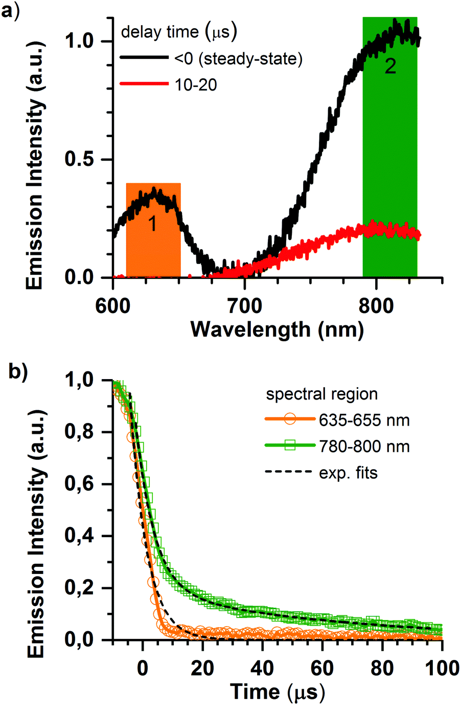 | ||
| Fig. 3 Time-resolved photoluminescence measurements of the Zn-BDC SURMOF loaded with carboxylic acid modified Pd porphyrin (Pd-Pr) excited at 410 nm under dynamic vacuum: (a) presents the emission spectra in specific integrated time window and shows the change from the steady state emission to exclusively triplet aggregate emission after 10 μs. (b) Presents the decay kinetics in the two spectral regions of interest. Pd-Pr monomer emission (635–655 nm) has a very short lifetime, whereas phosphorescence from Pd-Pr aggregates (780–800 nm) decays biexponentially with an average lifetime of 55 ± 5 μs. | ||
Analogous results are obtained for the Pt-Pr@SURMOF, shown in Fig. S2 (ESI†), revealing a similar kind of aggregate behavior with kinetics decay that can be fitted with a biexponential decay. Taken together with the broadened absorption spectra shown in Fig. 2, these data suggest that in both the Pd-Pr@SURMOF and Pt-Pr@SURMOF the majority of the dyes are found in such close proximity that they interact with their neighbors.
The emissive properties of the Zn-Pr are substantially different from Pd-Pr and Pt-Pr. In Zn-Pr intersystem crossing is not dominant, and the light emission stems from the singlet population. However, in Fig. 4a we see that intermolecular interactions in the Zn-Pr@SURMOF also significantly affect the photophysical properties of the dye in this case. In panel Fig. 4a we observe that the steady-state emission red-shifts and loses its features in comparison to the solution spectrum (50 μM dye in ethanol) upon loading into the SURMOF. In panel Fig. 4b we see that the lifetime of the dye is also strongly quenched in the SURMOF. The Zn-Pr in solution has life time of is 2.06 ± 0.05 ns on the other hand the Zn-Pr inside SURMOF has a decay with average life-time of 0.12 ± 0.02 ns.
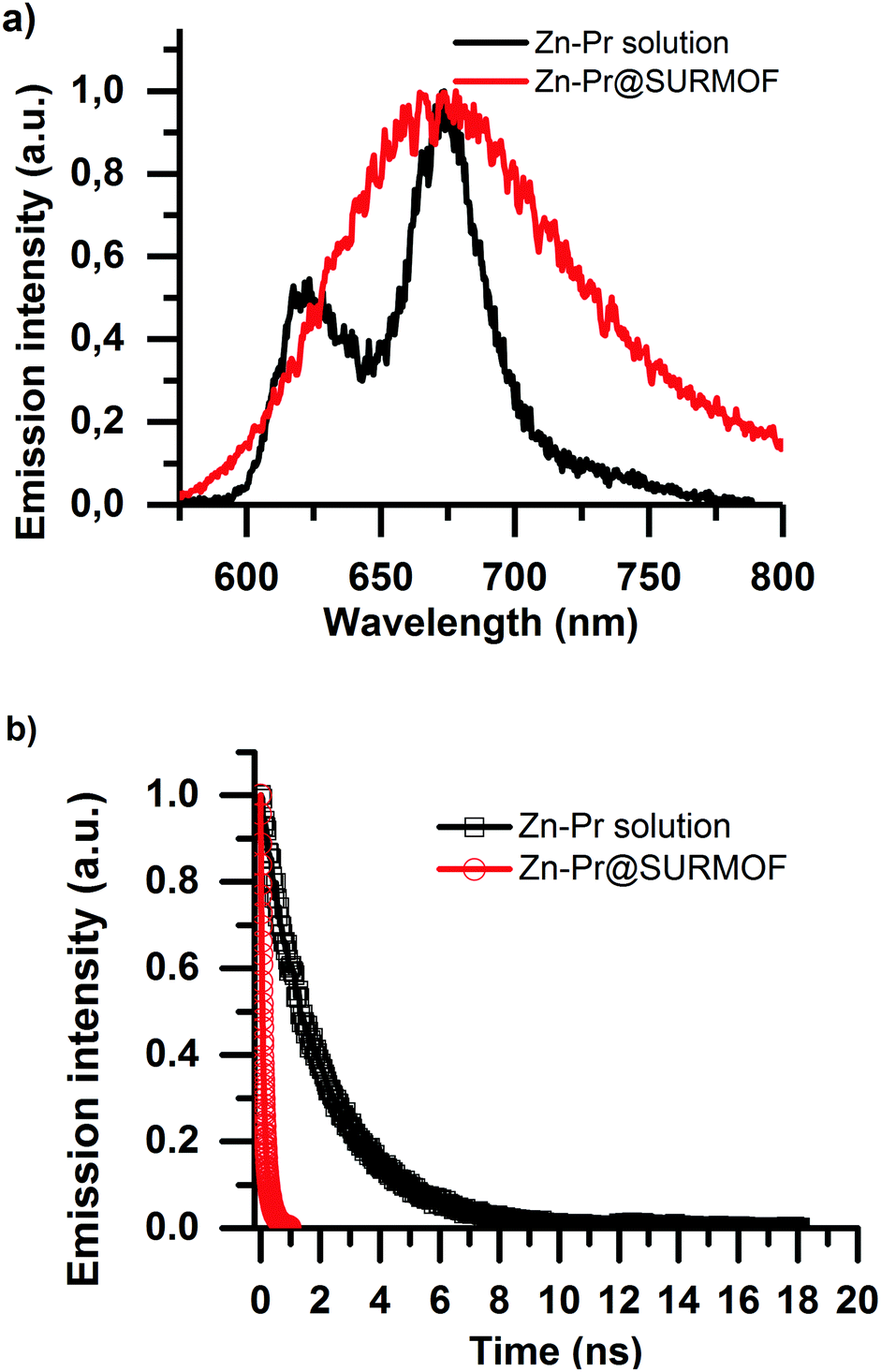 | ||
| Fig. 4 Photoluminescence measurements of the Zn BDC SURMOF loaded with carboxylic acid modified Zn porphyrin excited at 410 nm under dynamic vacuum. Panel (a) shows the difference between the steady-state emission spectra of the Zn-Pr@SURMOF and the Zn-Pr dye in a 50 μM ethanolic solution. The emission spectrum of the Zn-Pr in the SURMOF is broadened with respect to the Zn-Pr solution. Panel (b) shows the photoluminescence decay in the two samples. The aggregation is also confirmed by the decreased lifetime of the Zn-Pr when embedded in the SURMOF. | ||
In summary, the two equal but orthogonal dipole moments of the porphyrin means that both H and J-like aggregate interactions can occur between two molecules in an edge-on configuration. This is schematically illustrated in Fig. 5. The presence of both of these aggregate interactions is consistent with the broadening of the absorption spectrum (shifting absorption both to the red and blue), as well as the significant alteration in the emission energy and kinetics. Thus, the planar-like dye with Lewis-base functionality can be easily loaded within the Zn-BDC SURMOF that the dyes are taken up at such a concentration that strong intermolecular interactions come to limit the emissive properties of the dyes.
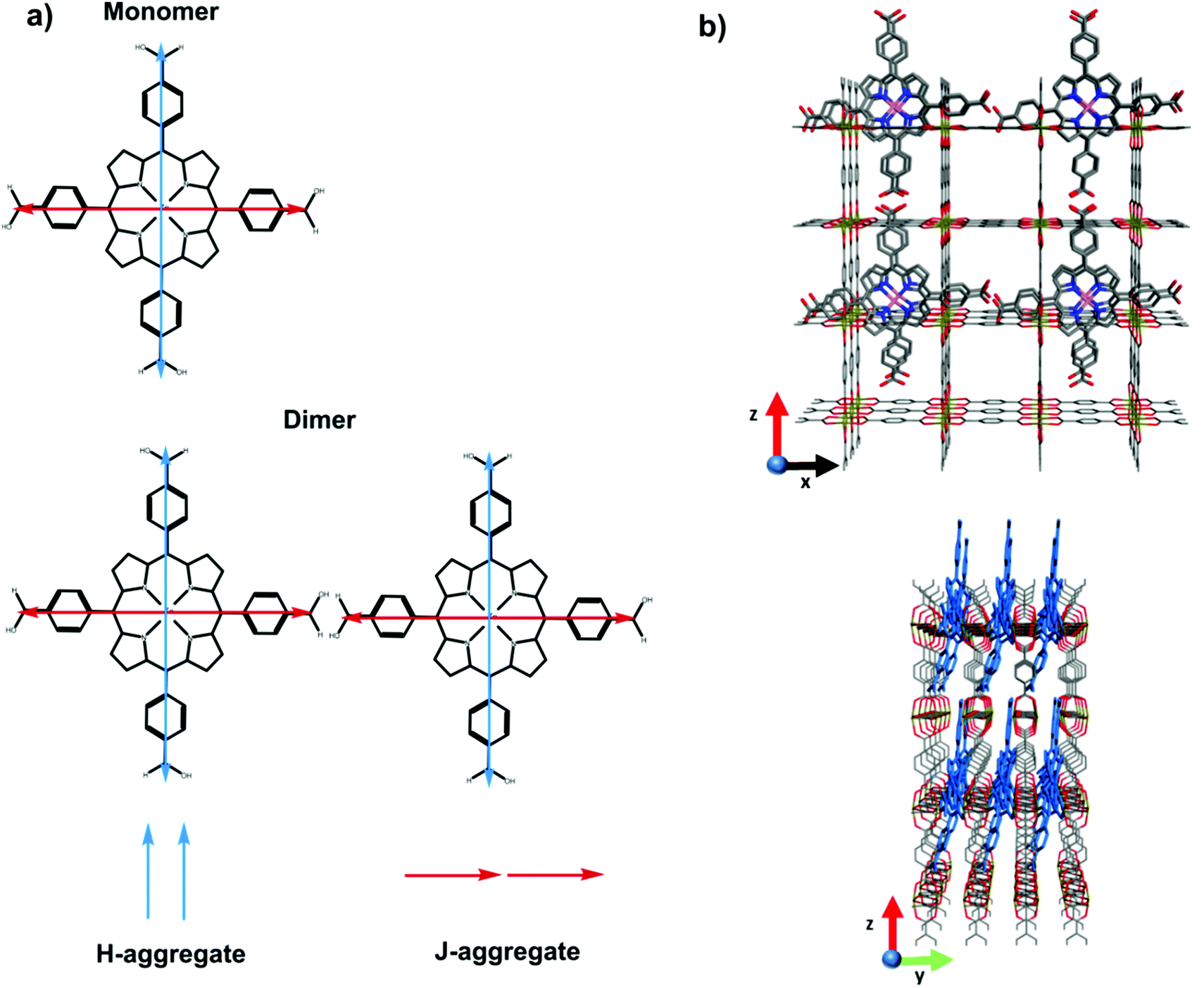 | ||
| Fig. 5 Panel (a) shows schematic of the two orthogonal but equivalent dipole transition moments in the monomer, and how these two orthogonal dipoles interact in an edge-on dimer configuration expected between the dyes loaded between SURMOF sheets. In the edge-on dimer the dipoles in blue form an H-type aggregate whereas those in red form a J-type aggregate. Panel (b) schematic illustration of porphyrin molecules within the SURMOF structure. | ||
Conclusion
In this work, we demonstrated that it is possible to load metallated porphyrin molecules with carboxylic groups, via direct drop casting from ethanol solution, inside ZnBDC SURMOF. Equivalent dyes without the carboxylic groups could not be loaded into the SURMOF. The proof of dye loading was provided by ToF-SIMS data. Using this technique, it was possible to observe the presence of the metal center of the porphyrin in throughout the whole thickness of the sample confirming that the dyes were actually loaded between the SURMOF-2 planes and not only on the surface. Then we performed optical characterization to study the behavior of the dyes inside the SURMOF structure and their aggregation state. We observed evidence of aggregation in terms of broadening of the absorption and emission spectra and a reduction in the photoluminescence lifetime. The chemical characteristics of guest molecules play an important role in determining whether they load or not. Our finding that carboxylic groups enable facile and high-density guest loading by drop-casting a dye solution onto a prefabricated SURMOF substrate opens avenues for designing inks for printing active optoelectronic guest molecules into SURMOFs. From a device perspective, being able to print patterned modifications of the SURMOF properties would provide interesting new design possibilities.Acknowledgements
We gratefully acknowledge support by the Helmholtz Association via the Professorial Recruitment Initiative for B. S. Richards, as well as the Helmholtz program Science and Technology of Nanosystems (STN). N. Baroni also gratefully acknowledges the financial support provided via a Karlsruhe School of Optics & Photonics (KSOP) PhD scholarship. SIMS analyses were supported by the Laboratory for Microscopy and Spectroscopy of the Karlsruhe Nano Micro Facility. I. A. Howard thanks the Baden-Württemberg Stiftung for financial support.References
- T.-H. Chen, I. Popov, W. Kaveevivitchai and O. Š. Miljanić, Chem. Mater., 2014, 26, 4322–4325 CrossRef CAS.
- S. Aguado and D. Farrusseng, Metal-Organic Frameworks, Wiley-VCH Verlag GmbH & Co. KGaA, 2011, pp. 121–149 Search PubMed.
- G. D. Pirngruber and P. L. Llewellyn, Metal-Organic Frameworks, Wiley-VCH Verlag GmbH & Co. KGaA, 2011, pp. 99–119 Search PubMed.
- S. Han, Y. Wei, C. Valente, I. Lagzi, J. J. Gassensmith, A. Coskun, J. F. Stoddart and B. A. Grzybowski, J. Am. Chem. Soc., 2010, 132, 16358–16361 CrossRef CAS PubMed.
- B. Van de Voorde, B. Bueken, J. Denayer and D. De Vos, Chem. Soc. Rev., 2014, 43, 5766–5788 RSC.
- P.-Z. Li, J. Su, J. Liang, J. Liu, Y. Zhang, H. Chen and Y. Zhao, Chem. Commun., 2017, 53, 3434–3437 RSC.
- S.-R. Zhang, J. Li, D.-Y. Du, J.-S. Qin, S.-L. Li, W.-W. He, Z.-M. Su and Y.-Q. Lan, J. Mater. Chem. A, 2015, 3, 23426–23434 CAS.
- M. Muller, A. Devaux, C.-H. Yang, L. De Cola and R. A. Fischer, Photochem. Photobiol. Sci., 2010, 9, 846–853 Search PubMed.
- P. Falcaro, R. Ricco, C. M. Doherty, K. Liang, A. J. Hill and M. J. Styles, Chem. Soc. Rev., 2014, 43, 5513–5560 RSC.
- T. Song, J. Yu, Y. Cui, Y. Yang and G. Qian, Dalton Trans., 2016, 45, 4218–4223 RSC.
- M. D. Allendorf, M. E. Foster, F. Léonard, V. Stavila, P. L. Feng, F. P. Doty, K. Leong, E. Y. Ma, S. R. Johnston and A. A. Talin, J. Phys. Lett., 2015, 6, 1182–1195 CAS.
- Y. Cui, B. Li, H. He, W. Zhou, B. Chen and G. Qian, Acc. Chem. Res., 2016, 49, 483–493 CrossRef CAS PubMed.
- A. Dragasser, O. Shekhah, O. Zybaylo, C. Shen, M. Buck, C. Woll and D. Schlettwein, Chem. Commun., 2012, 48, 663–665 RSC.
- A. A. Talin, A. Centrone, A. C. Ford, M. E. Foster, V. Stavila, P. Haney, R. A. Kinney, V. Szalai, F. El Gabaly, H. P. Yoon, F. Léonard and M. D. Allendorf, Science, 2014, 343, 66–69 CrossRef CAS PubMed.
- K. J. Erickson, F. Léonard, V. Stavila, M. E. Foster, C. D. Spataru, R. E. Jones, B. M. Foley, P. E. Hopkins, M. D. Allendorf and A. A. Talin, Adv. Mater., 2015, 27, 3453–3459 CrossRef CAS PubMed.
- X. Chen, Z. Wang, Z. M. Hassan, P. Lin, K. Zhang, H. Baumgart and E. Redel, ECS J. Solid State Sci. Technol., 2017, 6, 150–153 CrossRef.
- J. An, C. M. Shade, D. A. Chengelis-Czegan, S. Petoud and N. L. Rosi, J. Am. Chem. Soc., 2011, 133, 1220–1223 CrossRef CAS PubMed.
- C.-Y. Sun, X.-L. Wang, X. Zhang, C. Qin, P. Li, Z.-M. Su, D.-X. Zhu, G.-G. Shan, K.-Z. Shao, H. Wu and J. Li, Nat. Commun., 2013, 4, 2717 Search PubMed.
- Z.-G. Gu, Z. Chen, W.-Q. Fu, F. Wang and J. Zhang, ACS Appl. Mater. Interfaces, 2015, 7, 28585–28590 CAS.
- H. C. Streit, M. Adlung, O. Shekhah, X. Stammer, H. K. Arslan, O. Zybaylo, T. Ladnorg, H. Gliemann, M. Franzreb, C. Wöll and C. Wickleder, ChemPhysChem, 2012, 13, 2699–2702 CrossRef CAS PubMed.
- J. Yu, Y. Cui, H. Xu, Y. Yang, Z. Wang, B. Chen and G. Qian, Nat. Commun., 2013, 4, 2719 Search PubMed.
- J. Yu, Y. Cui, C. Wu, Y. Yang, Z. Wang, M. O'Keeffe, B. Chen and G. Qian, Angew. Chem., Int. Ed., 2012, 51, 10542–10545 CrossRef CAS PubMed.
- W. Guo, Z. Chen, C. Yang, T. Neumann, C. Kubel, W. Wenzel, A. Welle, W. Pfleging, O. Shekhah, C. Woll and E. Redel, Nanoscale, 2016, 8, 6468–6472 RSC.
- D. Zacher, O. Shekhah, C. Woll and R. A. Fischer, Chem. Soc. Rev., 2009, 38, 1418–1429 RSC.
- A. Bétard and R. A. Fischer, Chem. Rev., 2012, 112, 1055–1083 CrossRef PubMed.
- L. Heinke, Z. Gu and C. Wöll, Nat. Commun., 2014, 5, 4562 CAS.
- G. F. de Lima, A. Mavrandonakis, H. A. de Abreu, H. A. Duarte and T. Heine, J. Phys. Chem. C, 2013, 117, 4124–4130 CAS.
- Z. Akimbekov, D. Wu, C. K. Brozek, M. Dinca and A. Navrotsky, Phys. Chem. Chem. Phys., 2016, 18, 1158–1162 RSC.
- H. K. Kim, W. S. Yun, M.-B. Kim, J. Y. Kim, Y.-S. Bae, J. Lee and N. C. Jeong, J. Am. Chem. Soc., 2015, 137, 10009–10015 CrossRef CAS PubMed.
- J. Liu, W. Zhou, J. Liu, I. Howard, G. Kilibarda, S. Schlabach, D. Coupry, M. Addicoat, S. Yoneda, Y. Tsutsui, T. Sakurai, S. Seki, Z. Wang, P. Lindemann, E. Redel, T. Heine and C. Wöll, Angew. Chem., Int. Ed., 2015, 54, 7441–7445 CrossRef CAS PubMed.
- A. M. Ullman, J. W. Brown, M. E. Foster, F. Léonard, K. Leong, V. Stavila and M. D. Allendorf, Inorg. Chem., 2016, 55, 7233–7249 CrossRef CAS PubMed.
- H. K. Arslan, O. Shekhah, J. Wohlgemuth, M. Franzreb, R. A. Fischer and C. Wöll, Adv. Funct. Mater., 2011, 21, 4228–4231 CrossRef CAS.
- S. Kaskel, The Chemistry of Metal–Organic Frameworks: Synthesis, Characterization, and Applications, Wiley VGH, 2016 Search PubMed.
- P. Bhyrappa and K. S. Suslick, J. Porphyrins Phthalocyanines, 1998, 2, 391–396 CrossRef CAS.
- C. W. Leishman and J. L. McHale, J. Phys. Chem. C, 2016, 120, 15496–15508 CAS.
- N. Serpone and M. A. Jamieson, Coord. Chem. Rev., 1989, 93, 87–153 CrossRef CAS.
- S. Mandal, S. Kundu, S. Bhattacharyya and A. Patra, J. Mater. Chem. C, 2014, 2, 8691–8699 RSC.
- J. Kalinowski, W. Stampor, J. Szmytkowski, M. Cocchi, D. Virgili, V. Fattori and P. Di Marco, J. Chem. Phys., 2005, 122, 154710 CrossRef CAS PubMed.
- T. Dienel, H. Proehl, T. Fritz and K. Leo, J. Lumin., 2004, 110, 253–257 CrossRef CAS.
- F. Deng, J. Blumhoff and F. N. Castellano, J. Phys. Chem. A, 2013, 117, 4412–4419 CrossRef CAS PubMed.
- V. N. Knyukshto, E. I. Sagun, A. M. Shul’ga, S. M. Bachilo, D. A. Starukhin and É. I. Zen’kevich, Opt. Spectrosc., 2001, 90, 67–77 CrossRef CAS.
- J. A. S. Cavaleiro, H. Görner, P. S. S. Lacerda, J. G. MacDonald, G. Mark, M. G. P. M. S. Neves, R. S. Nohr, H.-P. Schuchmann, C. von Sonntag and A. C. Tomé, J. Photochem. Photobiol., A, 2001, 144, 131–140 CrossRef CAS.
Footnote |
| † Electronic supplementary information (ESI) available. See DOI: 10.1039/c7qm00142h |
| This journal is © the Partner Organisations 2017 |