
Facile synthesis and shape evolution of well-defined phosphotungstic acid potassium nanocrystals as a highly efficient visible-light-driven photocatalyst†
Xinran
Li
,
Huaiguo
Xue
and
Huan
Pang
 *
*
College of Chemistry and Chemical Engineering, Yangzhou University Yangzhou, Jiangsu 225002, China. E-mail: huanpangchem@hotmail.com; panghuan@yzu.edu.cn
First published on 21st November 2016
Abstract
Uniform and hollow rhombic dodecahedral, rhombic dodecahedral, spherical, and semi-hollow K3PW12O40·nH2O nanocrystals are fabricated without any surfactants or templating agents in mild hydrothermal conditions. The shape evolution and growth of these crystals are studied by changing different reaction parameters, such as the reagent, time and temperature. It is found that the temperature and time have significant effects on the possible growth processes of these nanostructures. More importantly, according to photocatalytic results, due to the specific nanostructure-hollow rhombic dodecahedral structure, the hollow rhombic dodecahedral K3PW12O40·nH2O particles with nanopores are shown to be the most effective at activating H2O2, degrading dye pollutants completely after 90 minutes of visible light radiation. What's more, the good recycle lifetime for the hollow rhombic dodecahedral K3PW12O40·nH2O particles makes them practical for industrial applications. Possible mechanisms for the photocatalysis reaction are further discussed.
Introduction
Over the past years, many scientists have shown great research interest in synthesizing shape-controlled inorganic materials due to their specific shape/size-dependent features.1 Therefore, these chemical syntheses have been extensively applied to the targeted synthesis and self-assembly of advanced micro/nanostructures: for example, biomimetic technology or the assistance of a specific surfactant agent are common ways to control the micro/nanostructure synthesis of a nanowire/nanofiber,2,3 nanosheet,4 nanocube,5 nanooctahedron,6 or nanohollow.7 However, there is a lack of deeper understanding on the formation mechanisms of the many micro/nanomaterials and hurdles are still being encountered, even though large numbers of fine architectures have now been perfectly fabricated using synthetic methods.Polyoxometalates (POMs) have well-defined inorganic metal–oxygen anionic clusters and coordinations. POMs combined with the right counter cations usually form solid materials that offer some unique features in the different fields of catalysis,8 magnetism,9 medical reagents,10 photoelectrochemistry11 and electrochemistry.12 Micro/nanostructured or self-organized POMs aggregating with outstanding properties have gained increasing attention,13–18 and groups such as Wang's group have successfully reported cluster-based self-assemblies of large inorganic metal–oxygen clusters to develop novel POM nanodisks, nanocones, and nanotubes at room temperature.16 A3[PM12O40] (A+ = NH4+, K+, Cs+, Ag+, etc.), a typical solid POM compound that is composed of inorganic monovalant cations and Keggin-type [PM12O40]3− (M = W, Mo) anions, is well studied. Noritaka Mizuno's group have successfully achieved the self-organization of M3PW12O40 crystals by changing the synthesis conditions.17 What's more, they also obtained rhombic bipyramidal cesium hydrogen silicododecatungstate in 2013.18 However, the development of a general method for obtaining controllable POM micro/nanostructures has been limited.
POMs have been applied as photocatalysts with increasing interest in recent years, for example as photocatalysts which efficiently remove heavy metal ions19–23 or pollutants from water.24,25 Visible light comprises more than 50% of solar light, and it is very important that pollutants are photodegraded by visible light to maximize the utilization of solar light. Many famous groups have explored effective methods for the catalytic decomposition of dye pollutants with the addition of visible irradiation.26–29 However, limited high performance photocatalysts have been fabricated.
Herein, we report the preparation of uniform and hollow rhombic dodecahedral, rhombic dodecahedral, spherical, and semi-hollow K3PW12O40·nH2O nanocrystals containing no templating agents or surfactants. Also, we have carefully studied the shape evolution of these nanocrystals. Interestingly, the temperatures and times of the reactions are important in the possible formation of targeted nanocrystals. From the photocatalytic experimental results, the nanostructured samples exhibit valid photocatalytic capacity for degrading pollutants by activating H2O2 under visible irradiation. Among these as-prepared samples, the hollow rhombic dodecahedral K3PW12O40·nH2O particles with nanopores are the most effective photocatalyst, activating H2O2 to degrade dye pollutants completely after 90 minutes of visible light radiation. More importantly, the hollow rhombic dodecahedral K3PW12O40·nH2O particle also shows good cycle life for re-usage, which makes it a promising photocatalyst in practical environmental treatments.
Results and discussion
A typical sample can be obtained under hydrothermal conditions using 150 mg of KCl and 300 mg of phosphotungstic acid at 140 °C for 12 h (for detailed information see the Experimental section). The corresponding XRD patterns are shown in Fig. S1,† and all of the peaks are indexed to the Keggin-type [PM12O40]3− crystal phase, which confirmed that the sample we prepared was K3PM12O40·nH2O.30 Its morphology was carefully observed using field emission scanning electron microscopy (FE-SEM) and transmission electron microscopy (TEM), as shown in Fig. 1 and 2. Uniform and hollow rhombic dodecahedral K3PW12O40·nH2O nanocrystals (denoted by S1) are seen in Fig. 1a. By close observation, there were individual nanocrystals with an average size of 450–500 nm in Fig. 1b, and there are shapeless nanopores with different sizes on the nanocrystal facets. In Fig. 1c–f, from different view points, nanopores were also found on different sites, which may promote contact with guest molecules.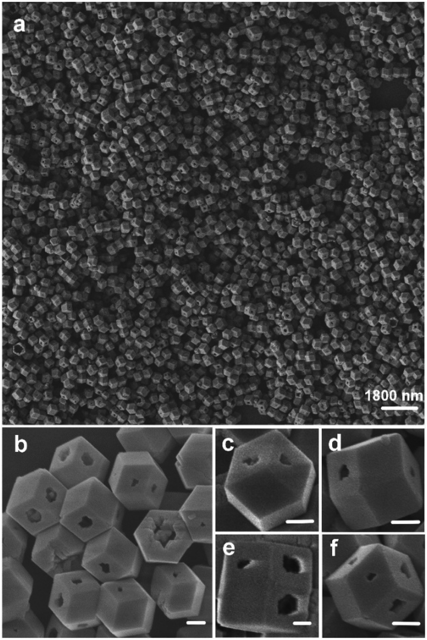 | ||
| Fig. 1 SEM images of the as-prepared samples obtained under hydrothermal conditions using 150 mg of KCl and 300 mg of phosphotungstic acid at 140 °C for 12 h (denoted by S1). (Scale bar of b–f is 180 nm). | ||
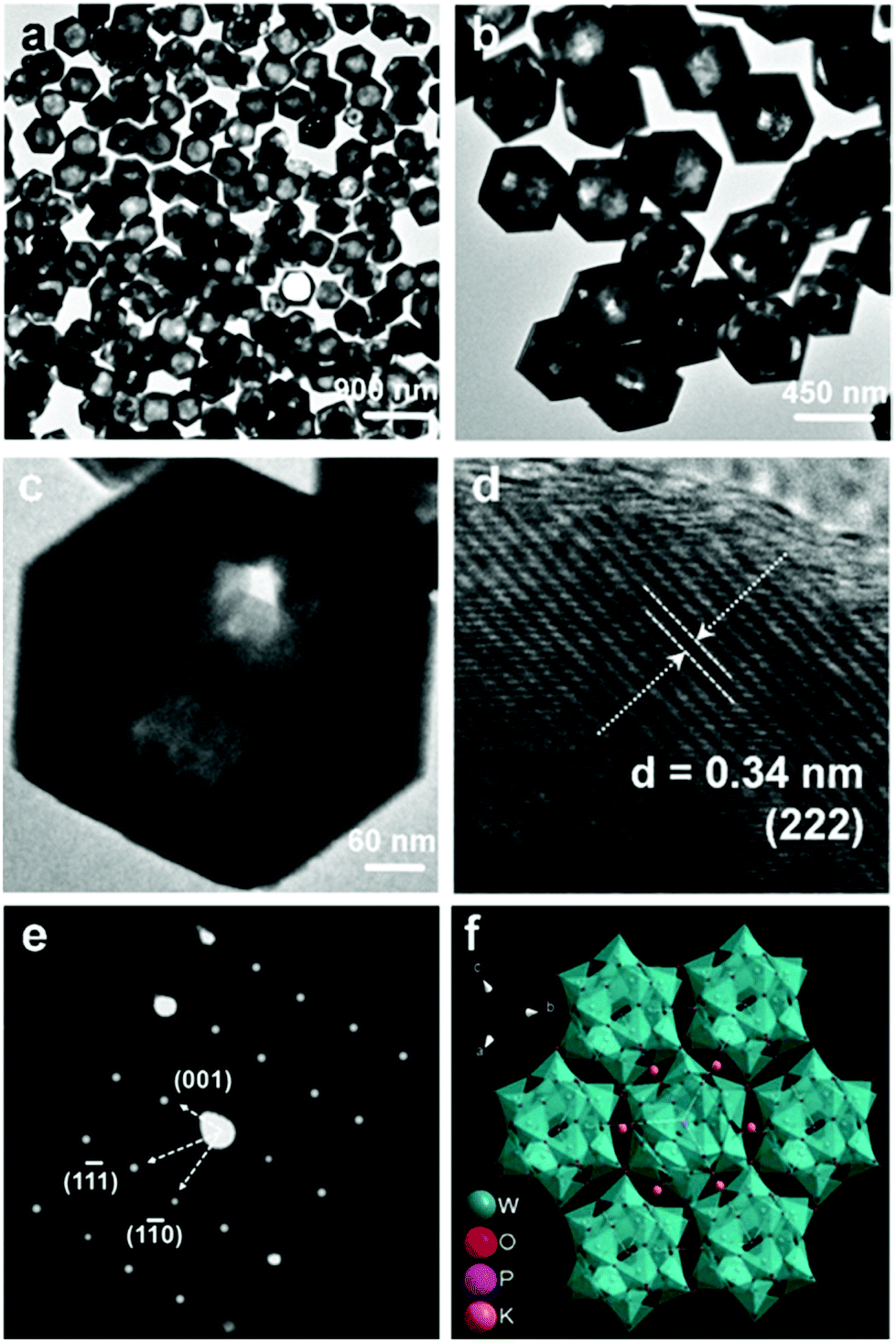 | ||
| Fig. 2 (a–c) TEM images, (d) HRTEM image and (e) SAED patterns of sample S1, and (f) crystal structure image of Keggin-type [PW12O40]3−. | ||
The TEM images shown in Fig. 2a–c demonstrate that the product has a well-defined hollow nanostructure, and the thickness is 80–90 nm for the corresponding shell in Fig. 2c. The selected area electron diffraction (SAED) and HRTEM images are shown in Fig. 2d and e, respectively. The crystal lattice distance of d = 0.34 nm is in accordance with the (222) crystal plane in Fig. 2d, and it is clear that the as-prepared S1 has a single crystalline property as proven by its corresponding symmetric cubic phase SAED pattern in Fig. 2e. Fig. 2f shows the crystal structure of Keggin-type [PW12O40]3− based on the data from ref. 30.
We have also studied the effect of the amount of reactants on the as-prepared samples’ morphologies. Decreasing the amounts to 80 mg of KCl and 200 mg of phosphotungstic acid, or increasing the amounts to 300 mg of KCl and 500 mg of phosphotungstic acid, led to little change in the morphologies (the SEM images are shown in Fig. S2a and b†).
Besides the amount of reactants, the temperature would also have an impact on the morphology control of the crystals. We reduced the temperature to 120 °C, and kept other conditions the same as for S1. Interestingly, uniform rhombic dodecahedral K3PW12O40·nH2O nanocrystals (denoted by S2) could be synthesized, as shown in Fig. 3. These crystals have different ways of stacking as seen in Fig. 3a and b. Obviously, the crystals are solid with an average size of 500 nm as seen in Fig. 3c–f, and the detailed micro/nanostructure is further observed in Fig. 3g. The crystal lattice distance in Fig. 3h is 0.34 nm, which is also indexed to the (222) crystal plane. The corresponding SAED is shown in Fig. 3i, and it is clearly shown by the highly symmetric SAED pattern that the as-prepared S2 has a single crystalline feature.
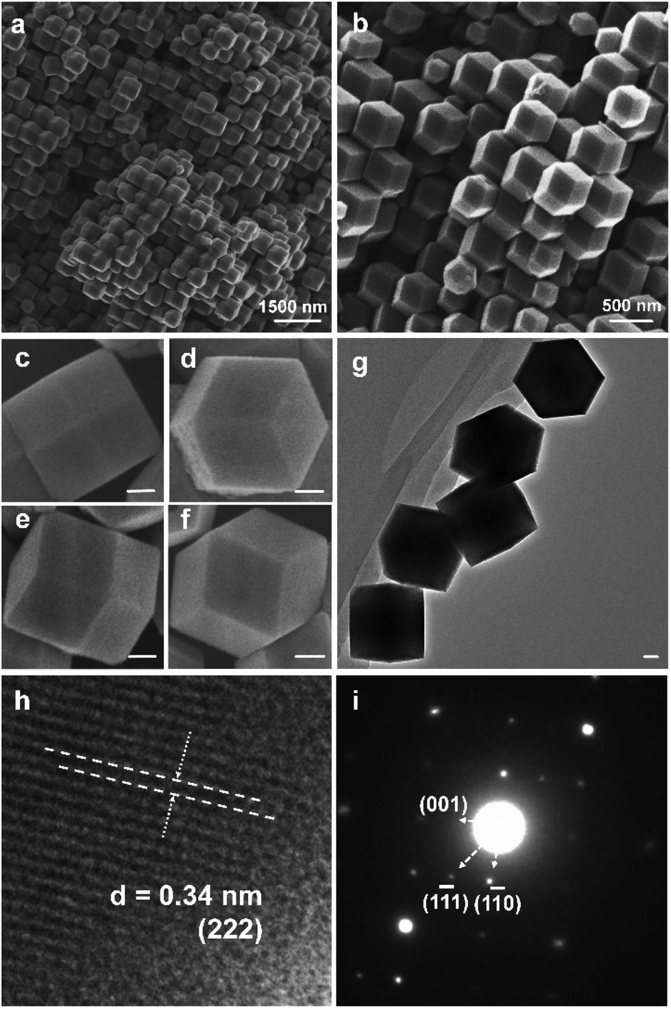 | ||
| Fig. 3 The samples (denoted by S2) prepared under hydrothermal conditions using 150 mg of KCl and 300 mg of phosphotungstic acid at 120 °C for 12 h. (a–f) SEM images, (g) TEM image, (h) HRTEM image, and (i) SAED patterns. (Scale bar shown in c–f represents 125 nm, and in g represents 95 nm). | ||
When decreasing the temperature to 100 °C, keeping other conditions the same as for S1, the morphology of the as-prepared samples changed into rough dodecahedral K3PW12O40·nH2O nanocrystals as shown in Fig. S3a.† Contrastingly, when increasing the temperature to 160 °C, the morphology of the as-prepared sample changed, as shown in Fig. S3d,† and some of the rhombic dodecahedral K3PW12O40·nH2O nanocrystals started to collapse. When further increasing the temperature to 200 °C, shapeless K3PW12O40·nH2O nanocrystals were formed (Fig. S3e†).
What's more, we further explored the influence of the reaction time on the final morphology. Uniform and spherical K3PW12O40·nH2O nanocrystals (denoted by S3) could be obtained under hydrothermal conditions using 150 mg of KCl and 300 mg of phosphotungstic acid at 100 °C for 1 h. Uniform and spherical K3PW12O40·nH2O particles are seen in Fig. 4a. By close observation, a single particle had an average diameter of 1000 nm (Fig. 4b and c). The TEM images shown in Fig. 4d–f also show the uniform and spherical nanostructures, and the particle size is the same as in the SEM results.
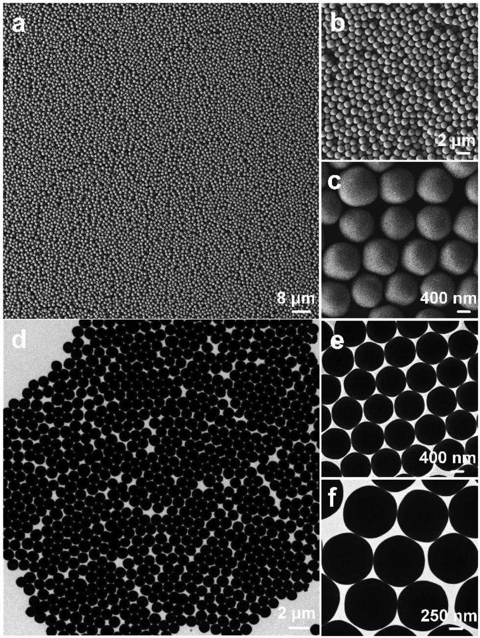 | ||
| Fig. 4 Samples (denoted by S3) obtained under hydrothermal conditions using 150 mg of KCl and 300 mg of phosphotungstic acid at 100 °C for 1 h. (a–c) SEM images, and (d–f) TEM images. | ||
The particle size became less uniform for the 3 h reaction time, as shown in Fig. S4b.† Semi-hollow and spherical K3PW12O40·nH2O particles (denoted by S4) were obtained under hydrothermal conditions using 150 mg of KCl and 300 mg of phosphotungstic acid at 100 °C for 6 h, which is a further prolonged reaction time (Fig. S5†). From Fig. S5a and b,† there are some broken shells of K3PW12O40·nH2O particles with a diameter of 1000 nm, which indicates that the particles might be hollow. To obtain detailed information on the insides of these particles, TEM images were taken and are further provided in Fig. S5c and d.† Different shading areas show the hollow and solid features. Interestingly, the semi-hollow spherical K3PW12O40·nH2O particles show a single crystal feature in their SAED patterns in the inset of Fig. S5d.†
To investigate the influence of the reaction time, different reaction times were used from 1 h to 24 h, as shown in Fig. S4.† The morphology of the product obtained after 9 h is close to that obtained after 6 h in Fig. S4d.† The morphology of the product obtained after 9 h has a rough rhombic dodecahedral architecture, and the analogous rhombic dodecahedral architecture was maintained from 12 to 24 h.
The possible reasons (or driving forces) for the transformation from rhombic dodecahedra to spheres and for the transition from solid to hollow are quite important to understand this work. However, self-organized aggregates of polyoxometalates are hard to find.31–38 Through a number of experiments, we found that the reaction temperature and time taken had important roles in the growth of K3PW12O40·nH2O, while the reagent led to little change in the morphology. As for the self-organization, it is not controllable and the mechanism is still unclear. Through repeated experiments and research, it is hard to elucidate the self-organization mechanism.
XRD patterns and XPS spectra of as-prepared K3PW12O40·nH2O are shown in Fig. S6 and S7.† The four as-prepared samples (S1, S2, S3, and S4) have the same crystal phase at the atomic scale, as shown in Fig. S6.† Also, K, W, P and O have the same chemical conditions in each crystal unit cell, as deduced from Fig. S7.† The signal at 36.6 eV can be attributed to W 4f, and the peak at 135 eV can be attributed to P 2p, which means that P(V) exists. The signal was also observed at a higher binding energy (around 292 eV and 531.1 eV), corresponding to K 2p and O 1s respectively. This is interesting for the comparison of the micro/nanostructure effects of the four samples (S1, S2, S3, and S4) on their photo-catalysis features. Fourier Transform infrared spectroscopy (FT-IR spectra) was performed to obtain structure information on the as-prepared K3PW12O40·nH2O (Fig. S8†). A broad absorption band at around 3450 cm−1 and the peak at 1617 cm−1 were indexed to the ν(OH) vibration and δ(H2O), respectively, which confirmed that crystallization water existed in the as-prepared samples. The typical Keggin anion skeletal vibration bands are the absorption bands at wavenumbers lower than 1300 cm−1 (for details, see discussion in Fig. S8†).39
The N2 adsorption–desorption isotherm of the as-fabricated samples (S1–S4) is shown in Fig. S9a.† It was worth noting that the Brunauer–Emmett–Teller (BET) specific surface area is 89, 43, 35, and 48 m2 g−1 for S1, S2, S3 and S4, respectively. Interestingly, the hysteresis loops in the isotherms in Fig. S8a† indicate the existence of mesopores in S1, and the Barrett–Joyner–Halenda (BJH) pore size distribution curves are further presented in Fig. S9b.† The small mesopores mainly originated from the analogous rhombic dodecahedral architecture and the typical Keggin anion structure, while the different pore sizes correspond to different void spaces of the hollow inner structure and the broken wall of the rhombic dodecahedral architecture. Specifically, S1 exhibited significantly porous structures. As is well known, mesopores play decisive roles in catalytic reactions due to their capability of facilitating mass and ion diffusion/transport, and ensure a highly activated mixture. So, the porous features of S1 affect its performance in photocatalytic applications.
UV-visible diffuse reflectance spectroscopy was performed to study the optical absorption conditions of the as-prepared K3PW12O40·nH2O. It was observed that all of the as-prepared K3PW12O40·nH2O nanocrystals had strong absorption in the UV-visible-light part of the spectrum (as shown in Fig. S10a†) due to the intrinsic band gap absorption of K3PW12O40·nH2O. In particular, compared with the visible-light section of the other samples, the absorption edge of S1 showed a red-shift. As a semiconductor crystal, the optical absorption around the band edge follows the equation (Chν)n = B(hν − Eg), where C is the coefficient, hν is the absorption photon energy, Eg is the band gap and B is a constant. Normally, “n” going through a semiconductor rests with the nature of the electron transitions, that is either 2 for direct inter-band transitions or 1/2 for indirect inter-band transitions.40,41 K3PW12O40·nH2O is a direct band gap semiconductor, and the corresponding n is 2. The (Chν)2vs. photon energy (hν) curve for the as-prepared K3PW12O40·nH2O is shown in Fig. S10b.† Furthermore, the as-prepared samples’ band gap energies (Eg values) were obtained by extrapolating the straight portion of the (Chν)2 − hν plot to the point C = 0. The values of the band gaps calculated using this method are S1 – 3.18 eV, S2 = S3 – 3.25 eV, and S4 – 3.21 eV. Generally, a narrow band gap may be caused by some interactions among free electrons, the lattice, and holes.42
Several POMs that activate H2O2 have been confirmed to catalyze the photodegradation of organic molecules under specific conditions.43,44 Using visible light irradiation, we found that Rhodamine B (RhB) underwent little degradation in only the RhB single system at room temperature, pH = 2.1 (Fig. 5). What's more, this phenomenon also exists in the K3PW12O40·nH2O-RhB system without H2O2 activation (shown in Fig. S11†) suggesting that the oxidant-H2O2 has a vital role in the dye photodecomposition. On the contrary, with visible light irradiation and H2O2 activation, K3PW12O40·nH2O nanomaterials can quickly lead to degradation of the RhB, as seen by the solution becoming completely colourless after 150 minutes of irradiation, especially for S1 (only 90 minutes). It is worth noting that during the first 60 minutes of irradiation, the four samples degraded RhB rapidly, and that S1 showed the highest degradation speed and efficiency, which can be obtained from the slope of the plot of the photodegradation extent of RhB (Fig. 5b). Notably, the degradation efficiency decreased after 60 minutes of irradiation, which may have been caused by the active sites of the K3PW12O40·nH2O nanomaterials being partly blocked by the intermediate product. However, the blocked effect is smallest for S1, and S1 also was the first sample that could degrade the RhB completely in 90 minutes of irradiation, while others did not do this. Compared with previous results of some reported nanostructures, including Ag3PO4/TiO2,45 Fe3O4-SiO2-TiO2/GO,46 PZT coupled with TiO2,47 Cu2ZnSnS4-Pt,48 α-Fe2O3 nanocrystals49 and α-Fe2O3 hollow microplatelets,50,51 as shown in Table S1,† we have found that the photocatalyst S1 can offer the highest degradation speed and 100% efficiency. These experimental results indicated that S1 has great potential as a photocatalyst in the application of decomposing organic pollutants under visible light irradiation.
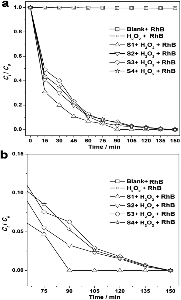 | ||
| Fig. 5 (a) A plot of the photodegradation extent of RhB on the basis of irradiation time for the blank and as-prepared samples, and (b) the amplification of the section from 60 to 150 min. | ||
The stability or recycle lifetime of the photocatalyst is significant for industrial applications. The recycle lifetime of the photocatalyst for S1 has been further studied and the results are shown in Fig. S12.† After the first cycle of photodegradation, the centrifuged catalyst S1 was dispersed into the same RhB system again. The photodegradation of RhB in the second run was the same efficiency as the first cycle. Furthermore, there was no significant loss after seven cycles of the degradation of RhB as shown in Fig. S11.† In other words, the catalyst (S1) is stable under such conditions.
The above photocatalysis results demonstrate the rapid degradation capacity for RhB of the hollow rhombic dodecahedral K3PW12O40·nH2O nanostructures (S1) in terms of the specific degradation speed, efficiency, and recycling ability. Particularly, the S1 sample presents the greatest photocatalysis capacity in all of the samples tested. The photocatalysis feature of S1 (the hollow rhombic dodecahedral structure) is considered to be much better compared to some other reported micro/nanostructures for photodegradation (Table S1†).45–51 We owe the excellent properties to the desirable and novel nanostructure. Specifically, first the hollow rhombic dodecahedral structure with nanopores provides a relatively high active surface area and many photocatalysis active sites, and secondly the hollow rhombic dodecahedral structure also reduces the undesirable agglomeration, which ensures the stability of the recycle usage. It is worth mentioning that the effect of abundant pores is very significant for the photocatalysis reaction. The abundantly porous hollow feature guarantees the fine penetration of the dye that promotes reactions on the surface and interface, and allows for a sufficiently high photocatalysis surface area. So, the high photocatalysis ability of S1 is further seen even after recycling 7 times. This could also present a satisfactory explanation for the high performance of the highly nanoporous S1.
Possible mechanisms for the photocatalysis reaction in this work were further discussed, and active oxygen radicals were captured by ESR spin-trapping methods. The corresponding spectra of the DMPO-O2˙− adducts under various visible light irradiation times are shown in Fig. S13.† Interestingly, several ESR signals appeared in the laser irradiation (532 nm), and these signals are typical patterns of DMPO-O2˙− adducts. The corresponding intensity increased with the prolonged irradiation, which indicates the continuous formation of O2˙−, as shown in Fig. S11.† The adsorbed H2O2 can quickly trap one electron in the LUMO of the as-prepared K3PW12O40·nH2O nanomaterials, which is from the excited dye. Consequently, the above reactions enable continuous electron injection (eqn (1) and (2)). In other words, due to the possible injected electrons (eqn (3)), H2O2 was reduced which caused the formation of ˙OH. As previously reported, the decomposition of H2O2 with co-existing metal oxides always obeys the “Haber–Weiss” process, where the superoxide radicals are formed as a result of the reaction between the H2O2 and ˙OH as shown in eqn (4).52 So, the formed ˙OH radical can attack H2O2, and HOO˙ can be formed. The ˙OOH can photocatalytically degrade dyes under visible irradiation as previously reported, as shown in eqn (5).53,54
| dye + visible light = dye* | (1) |
| dye* + K3PW12O40 = dye˙+ + e−(K3PW12O40) | (2) |
| H2O2 + e−(K3PW12O40) = HO− + ˙OH(K3PW12O40) | (3) |
| H2O2 + ˙OH = HOO˙ + H2O | (4) |
| dye˙+ + HOO˙ = dye degradation | (5) |
Experimental section
Synthesis of typical samples
(S1) 150 mg of KCl and 300 mg of phosphotungstic acid were heated at 140 °C for 12 h under hydrothermal conditions; (S2) 150 mg of KCl and 300 mg of phosphotungstic acid were heated at 120 °C for 12 h under hydrothermal conditions; (S3) 150 mg of KCl and 300 mg of phosphotungstic acid were heated at 100 °C for 1 h under hydrothermal conditions, and (S4) 150 mg of KCl and 300 mg of phosphotungstic acid were heated at 100 °C for 6 h under hydrothermal conditions; all of the samples should be washed several times with deionized water and alcohol respectively after the hydrothermal treatment, and then dried in air naturally.Characterizations
The morphology of the as-prepared samples was observed using a JEOL JSM-6701F field-emission scanning electron microscope (FE-SEM) at an acceleration voltage of 5.0 kV. The phase analyses of the samples were performed using X-ray diffraction (XRD) on a Rigaku-Ultima III diffractometer with Cu Kα radiation (λ = 1.5418 Å). Transmission electron microscopy (TEM) images were captured on the JEM-2100 instrument at an acceleration voltage of 200 kV. Nitrogen adsorption–desorption measurements were performed on a Gemini VII 2390 Analyzer at 77 K using the volumetric method. The specific surface area was obtained from the N2 adsorption–desorption isotherms and was calculated using the Brunauer–Emmett–Teller (BET) method. The UV-vis diffuse reflectance spectra (DRS) of the samples were recorded using a UV-vis spectrophotometer (UV-3600, Shimadzu, Japan), and BaSO4 was used as a reference. The ESR measurements (radicals spin-trapped by spin-trap reagent 5,5-dimethyl-1-pyrroline N-oxide (DMPO), purchased from Sigma Chemical Co.) were performed using a Bruker A300 spectrometer operating in X-band (9.862 GHz) at 25 °C.Photocatalytic investigation
The visible light source was a 500 W halogen lamp covered with a cylindrical glass vessel with a recycling water glass jacket. In order to remove all of the radiation at wavelengths below 420 nm, a cutoff filter was placed outside the water jacket to completely ensure that there was only illumination from visible light. The as-prepared samples (S1, S2, S3 or S4), dye solution and H2O2 solution dispersions were mixed together by the addition of the as-prepared sample to a 25 mL solution containing H2O2 and RhB dye (initial concentrations: RhB = 2 × 10⁻⁵ M, H2O2 = 2 × 10⁻³ M; as-prepared samples = 0.5 g L−1, pH = 2.1). Prior to irradiation, the above mixture was stirred for 30 minutes in the dark to hold an adsorption–desorption balance among RhB, H2O2, and the as-prepared samples. After the irradiation, a Na2CO3–NaHCO3 solution (0.5 mol L−1) was used to buffer the above mixture at pH = 9. More importantly, the solid as-prepared samples dissolved at this pH, which could minimize the effect from the adsorption of the dyes on the catalysts. A UV-visible spectrophotometer (Varian, CARY 50 Probe-America) was applied to measure the temporal UV-visible spectral variations.Conclusions
In summary, uniform hollow rhombic dodecahedral, rhombic dodecahedral, spherical, and semi-hollow K3PW12O40·nH2O nanocrystals have been successfully obtained without any surfactants or templating agents. What's more, the shape evolution of these nanocrystals also has been carefully studied. It is surprising that the temperatures and reaction times play significant roles in the possible process of growth of these nanostructures. More importantly, these nanostructured samples show effective photocatalytic capacity for the degradation of pollutants by activating H2O2 under visible irradiation from the photocatalytic testing results. The hollow rhombic dodecahedral K3PW12O40·nH2O particles with nanopores showed the most effective photodegradation ability by activating H2O2, which could degrade dye pollutants completely after visible light radiation for 90 minutes and be recycled effectively for 7 cycles. The hollow rhombic dodecahedral K3PW12O40·nH2O particles with nanopores are promising photocatalysts for practical environmental treatments.Acknowledgements
This work was supported by the Program for New Century Excellent Talents of the University in China (grant no. NCET-13-645) and the National Natural Science Foundation of China (NSFC-21201010, 21671170, 21673203, 21505118 and 51202106), Innovation Scientists and Technicians Troop Construction Projects of Henan Province (164200510018), Program for Innovative Research Team (in Science and Technology) in University of Henan Province (14IRTSTHN004, 16IRTSTHN003), the Science & Technology Foundation of Henan Province (122102210253 and 13A150019), Qinglan project of Jiangsu, the Six Talent Plan (2015-XCL-030), Graduate student scientific research innovation projects in Jiangsu province (SJLX16_0588) and the China Postdoctoral Science Foundation (2012M521115). We also acknowledge the Priority Academic Program Development of Jiangsu Higher Education Institutions and the technical support we received at the Testing Center of Yangzhou University.References
- Y. Cui and C. M. Lieber, Science, 2001, 291, 851 CrossRef CAS PubMed.
- J. Jiang, Y. Y. Li, J. P. Liu, X. T. Huang, C. Z. Yuan and X. W. Lou, Adv. Mater., 2012, 24, 5166 CrossRef CAS PubMed.
- H. H. Li, S. Y. Ma, Q. Q. Fu, X. J. Liu, L. Wu and S. H. Yu, J. Am. Chem. Soc., 2015, 137, 7862 CrossRef CAS PubMed.
- M. J. Lyu, Y. W. Liu, Y. D. Zhi, C. Xiao, B. C. Gu, X. M. Hua, S. J. Fan, Y. Lin, W. Bai, W. Tong, Y. M. Zou, B. C. Pan, B. J. Ye and Y. Xie, J. Am. Chem. Soc., 2015, 137, 15043 CrossRef CAS PubMed.
- F. R. Fan, D. Y. Liu, Y. F. Wu, S. Duan, Z. X. Xie, Z. Y. Jiang and Z. Q. Tian, J. Am. Chem. Soc., 2008, 130, 6949 CrossRef CAS PubMed.
- J. J. Ge, D. S. He, L. Bai, R. You, H. Y. Lu, Y. Lin, C. L. Tan, Y. B. Kang, B. Xiao, Y. E. Wu, Z. X. Deng, W. X. Huang, H. Zhang, X. Hong and Y. D. Li, J. Am. Chem. Soc., 2015, 137, 14566 CrossRef CAS PubMed.
- Y. M. Chen, Z. Li and X. W. Lou, Angew. Chem., Int. Ed., 2015, 54, 10521 CrossRef CAS PubMed.
- Y. Yang, B. Wang, Y. Z. Wang, L. Yue, W. Li and L. X. Wu, J. Am. Chem. Soc., 2013, 135, 14500 CrossRef CAS PubMed.
- M. Y. Zhu and G. W. Diao, Nanoscale, 2011, 3, 2748 RSC.
- M. Li, C. Xu, L. Wu, J. S. Ren, E. B. Wang and X. G. Qu, Small, 2013, 9, 3455 CrossRef CAS PubMed.
- M. Vasilopoulou, A. M. Douvas, L. C. Palilis, S. Kennou and P. Argitis, J. Am. Chem. Soc., 2015, 137, 6844 CrossRef CAS PubMed.
- J. S. Qin, D. Y. Du, W. Guan, X. J. Bo, Y. F. Li, L. P. Guo, Z. M. Su, Y. Y. Wang, Y. Q. Lan and H. C. Zhou, J. Am. Chem. Soc., 2015, 137, 7169 CrossRef CAS PubMed.
- D. L. Long, R. Tsunashima and L. Cronin, Angew. Chem., Int. Ed., 2010, 49, 1736 CrossRef CAS PubMed.
- C. L. Wu, L. Shen, H. G. Yu, Y. C. Zhang and Q. L. Huang, Mater. Lett., 2012, 74, 236 CrossRef CAS.
- A. Nisar, Y. Lu and X. Wang, Chem. Mater., 2010, 22, 3511 CrossRef CAS.
- A. Nisar, J. Zhuang and X. Wang, Chem. Mater., 2009, 21, 3745 CrossRef CAS.
- C. L. Wu, L. Shen, Q. L. Huang and Y. C. Zhang, Mater. Lett., 2011, 65, 1134 CrossRef CAS.
- Y. Ogasawara, S. Uchida, T. Maruichi, R. Ishikawa, N. Shibata, Y. Ikuhara and N. Mizuno, Chem. Mater., 2013, 25, 905 CrossRef CAS.
- W. Zhang, X. D. Gong, C. Liu, Y. Z. Piao, Y. Sun and G. W. Diao, J. Mater. Chem. B, 2014, 2, 5107 RSC.
- R. R. Ozer and J. L. Ferry, J. Phys. Chem. B, 2000, 104, 9444 CrossRef CAS.
- B. Yue, Y. Zhou, J. Y. Xu, Z. Z. Wu, X. A. Zhang, Y. F. Zou and S. L. Jin, Environ. Sci. Technol., 2002, 36, 1325 CrossRef CAS PubMed.
- A. Troupis and A. Hiskia, Environ. Sci. Technol., 2002, 36, 5355 CrossRef CAS PubMed.
- C. C. Chen, Q. Wang, P. X. Lei, W. J. Song, W. H. Ma and J. C. Zhao, Environ. Sci. Technol., 2006, 40, 3965 CrossRef CAS PubMed.
- P. Lei, C. Chen, J. Yang, W. Ma, J. C. Zhao and L. Zang, Environ. Sci. Technol., 2005, 39, 8466 CrossRef CAS PubMed.
- M. G. Wang, Y. M. Hu, J. Han, R. Guo, H. X. Xiong and Y. D. Yin, J. Mater. Chem. A, 2015, 3, 20727 RSC.
- C. C. Chen, W. H. Ma and J. C. Zhao, Chem. Soc. Rev., 2010, 39, 4206 RSC.
- C. S. Pan and Y. F. Zhu, Environ. Sci. Technol., 2010, 44, 5570 CrossRef CAS PubMed.
- W. L. Yang, L. Zhang, Y. Hu, Y. J. Zhong, H. B. Wu and X. W. Lou, Angew. Chem., Int. Ed., 2012, 51, 11501 CrossRef CAS PubMed.
- S. C. Yan, Z. S. Li and Z. G. Zou, Langmuir, 2009, 25, 10397 CrossRef CAS PubMed.
- J. He, H. Pang, W. Wang, Y. Zhang, B. Yan, X. R. Li, S. J. Li and J. Chen, Dalton Trans., 2013, 42, 15637 RSC.
- D. L. Long and L. Cronin, Chem. – Eur. J., 2006, 12, 3698 CrossRef CAS PubMed.
- J. T. Rhule, W. A. Neiwert, K. I. Hardcastle, B. T. Do and C. L. Hill, J. Am. Chem. Soc., 2001, 123, 12101 CrossRef CAS PubMed.
- A. Muller, S. Q. N. Shah, H. Bogge and M. Schmidtmann, Nature, 1999, 397, 48 CrossRef CAS.
- T. Yamase and P. V. Prokop, Angew. Chem., Int. Ed., 2002, 41, 466 CrossRef CAS PubMed.
- T. Liu, E. Diemann, H. Li, A. W. M. Dress and A. Muller, Nature, 2003, 426, 59 CrossRef CAS PubMed.
- N. Mizuno and M. Misono, Chem. Lett., 1987, 967 CrossRef CAS.
- T. Ito, K. Inumaru and M. Misono, J. Phys. Chem. B, 1997, 101, 9958 CrossRef CAS.
- T. Okuhara, H. Watanabe, T. Nishimura, K. Inumaru and M. Misono, Chem. Mater., 2000, 12, 2230 CrossRef CAS.
- N. Essayem, A. Holmqvist, P. Y. Gayraud, J. C. Vedrine and Y. Ben Taarit, J. Catal., 2001, 197, 273 CrossRef CAS.
- L. P. Zhu, G. H. Liu, N. C. Bing, L. L. Wang, Y. Yang and H. Y. Xie, CrystEngComm, 2010, 12, 3791 RSC.
- L. Chen, S. F. Yin, R. Huang, Q. Zhang, S. L. Luo and C. T. Au, CrystEngComm, 2012, 14, 4217 RSC.
- T. Y. Zhao, J. T. Zai, M. Xu, Q. Zou, Y. Z. Su, K. X. Wang and X. F. Qian, CrystEngComm, 2011, 13, 4010 RSC.
- R. Noyori, M. Aoki and K. Sato, Chem. Commun., 2003, 1977 RSC.
- D. M. Gould, W. P. Griffith and M. Spiro, J. Mol. Catal. A: Chem., 2001, 175, 289 CrossRef CAS.
- W. Yao, B. Zhang, C. Huang, C. Ma, X. Song and Q. Xu, J. Mater. Chem., 2012, 22, 4050 RSC.
- F. Chen, F. Yan, Q. Chen, Y. Wang, L. Han, Z. Chen and S. Fang, Dalton Trans., 2014, 43, 13537 RSC.
- Q. Wu, D. Li, L. Wu, J. Wang, X. Fu and X. Wang, J. Mater. Chem., 2006, 16, 1116 RSC.
- X. Yu, A. Shavel, X. Q. An, Z. Luo, M. Ibanez and A. Cabot, J. Am. Chem. Soc., 2014, 136, 9236 CrossRef CAS PubMed.
- X. Zhou, J. Lan, G. Liu, K. Deng, Y. Yang, G. Nie, J. Yu and L. Zhi, Angew. Chem., Int. Ed., 2012, 124, 182 CrossRef.
- H. Liang, W. Chen, X. Jiang, X. Xu, B. Xu and Z. Wang, J. Mater. Chem. A, 2014, 2, 4340 RSC.
- N. Kitajima, S. Fukuzumi and Y. Ono, J. Phys. Chem., 1978, 82, 1505 CrossRef CAS.
- J. Bandara and J. Kiwi, New J. Chem., 1999, 23, 717 RSC.
- C. C. Chen, W. Zhao, P. X. Lei and J. C. Zhao, Chem. – Eur. J., 2004, 10, 1956 CrossRef CAS PubMed.
- M. Stylidi, D. Kondarides and X. Verykios, Appl. Catal., B, 2004, 47, 189 CrossRef CAS.
Footnote |
| † Electronic supplementary information (ESI) available. See DOI: 10.1039/c6nr07680g |
| This journal is © The Royal Society of Chemistry 2017 |