
Role of lanthanum species in improving the photocatalytic activity of titanium dioxide
Wai Ruu
Siah
a,
Hendrik O.
Lintang
ab and
Leny
Yuliati
 *ab
*ab
aCentre for Sustainable Nanomaterials, Ibnu Sina Institute for Scientific and Industrial Research, Universiti Teknologi Malaysia, 81310 UTM Johor Bahru, Johor, Malaysia
bMa Chung Research Centre for Photosynthetic Pigments, Universitas Ma Chung, Villa Puncak Tidar N-01, Malang 65151, East Java, Indonesia. E-mail: leny.yuliati@machung.ac.id
First published on 18th November 2016
Abstract
Series of lanthanum-modified TiO2 catalysts were prepared by a UV photodeposition method to exclude any heat treatments that may affect the properties and photocatalytic activity of TiO2. Results showed that the lanthanum modification did not significantly affect the properties of TiO2, but increased the formation of Ti3+. Under UV light irradiation, the activity for 2,4-D decomposition rose by a maximum factor of 5.5 when TiO2 was loaded with 5 mol% La; further increase of La deposition led to a decrease in photocatalytic activity. From the electrochemical impedance and photocurrent results, it was shown that the positive influence of La on TiO2 photocatalytic activity was caused by the increased charge separation in the TiO2 photocatalysts, owing to the additional formation of Ti3+ states. On the other hand, when tested with the colourless 2,4-D model pollutant under visible and solar simulator irradiation, the presence of lanthanum species did not improve the photocatalytic activity of TiO2 significantly. Hence, it was shown that lanthanum species only improved the UV photocatalytic activity of TiO2.
Introduction
In recent years, photocatalytic degradation has attracted considerable attention as this approach could be used to remove organic pollutants, hence providing a promising solution for wastewater treatment and purification of polluted air. Titanium dioxide (TiO2) is one of the main photocatalysts used for this purpose due to the strong oxidizing power of its photogenerated holes, its chemical stability, non-toxicity and low cost.1 However, the photocatalytic performance of TiO2 was limited by the fast recombination of its photogenerated electrons and holes. Transition metal oxide2–4 and rare earth metal oxide5,6 co-catalysts supported on TiO2 have been found to enhance the photocatalytic activity of TiO2. Among the rare earth elements, lanthanum oxide7–39 is considered as a suitable co-catalyst due to its ability to suppress electron–hole recombination of TiO2 and its relative abundance. To date, there are numerous reports on the effects of lanthanum modifications on the photocatalytic activity of TiO2 either under UV,7–13 visible14–32 or solar33–39 irradiation. While all studies reported the enhanced activity under UV light, there are some contradictions on the effect of lanthanum species on the visible light activity of TiO2. Some studies showed that lanthanum modification of TiO2 led to the occurrence of visible light activity of TiO2,14–28 while others reported that the added lanthanum did not contribute to the photocatalytic activity of TiO2 under visible light irradiation.29–32 Taking into account that visible light is the main component of solar light, in contrast all papers reported the beneficial effect of lanthanum species in improving the activity of TiO2 under solar irradiation.33–39Besides the contradicting activity enhancement between those under visible and solar light, there is also unclear discussion on the role of lanthanum species in improving the activity of TiO2 photocatalysts. In these reported studies, the La-modified TiO2 photocatalysts were prepared by sol–gel,7–11,14–18,29,30,33–36 co-precipitation,7 hydrothermal synthesis,19,20 cathodic electrochemical processes,37 and impregnation methods,38 which generally involved calcination of the La–TiO2 catalysts at high temperatures (200–800 °C). Due to the use of high temperatures, the properties of TiO2 such as the crystallite size7–11,14–20,30,33–38 and anatase–rutile ratio7–9,15–18,20,29,33,34,36–38 were affected. Since these properties also contributed to the photocatalytic activity of TiO2, the role of lanthanum species alone in improving the photocatalytic activity of TiO2 might not be addressed correctly.
In order to directly investigate the role of the lanthanum species, a synthesis method that does not involve heat treatment shall be employed. One of the promising methods for deposition of lanthanum oxide on the surface of TiO2 without any heat treatments is UV photodeposition. This method is recognized as an effective and environmentally friendly method as it could be carried out at room temperature under mild experimental conditions. The photodeposition process involves the photodecomposition of metal precursors in the presence of TiO2 and UV irradiation, releasing metal ions that in turn interact with the surface of TiO2.
In the present study, we deposited the lanthanum oxide on the TiO2 support via a simple UV photodeposition method conducted at room temperature. Such mild synthesis temperature allowed us to investigate the role of lanthanum species while excluding the effects of other factors aforementioned. The photocatalytic activity of the catalysts was evaluated for the degradation of 2,4-dichlorophenoxyacetic acid (2,4-D), which is a colourless pollutant, under UV, visible, and solar simulator irradiation. The colourless 2,4-D was selected to avoid the possibility that the enhancement in the activity was caused by the effect of pollutant sensitization when the reaction was performed under visible or solar light irradiation. This study demonstrated that under UV irradiation, La-modified TiO2 showed an excellent photocatalytic activity compared to the unmodified TiO2, while such enhancement was not observed for reactions under visible and solar light irradiation, suggesting that the lanthanum species did not contribute to the visible light activity.
Experimental
Preparation of Laox/TiO2 photocatalysts
The series of La oxide-modified TiO2 catalysts were prepared by a UV photodeposition method. Hombikat UV100 TiO2 (HK UV100) was used as-received from Sachtleben Chemie. In the first step, the required amount of lanthanum(III) acetylacetonate hydrate (TCI, >98.0%) was combined with HK UV100 TiO2 (1 g) and added to 20 mL of water/ethanol mixture (1![[thin space (1/6-em)]](https://www.rsc.org/images/entities/char_2009.gif) :1 v/v) in a beaker (100 mL). The mixture was sonicated for 5 min to obtain a homogeneous suspension, followed by exposure to a UV lamp (200 W, ΦI = 8 mW cm−2) from the top for 5 h under ambient conditions. The irradiated mixture was then centrifuged (3500 rpm, 20 min) to collect the solid sample. After rinsing with ethanol and distilled water, the sample was dried in an oven overnight at 80 °C and ground to a fine powder. The samples were denoted as Laox(x)/TiO2, where x represented the ratio of added La to TiO2 (0.1–10 mol%).
:1 v/v) in a beaker (100 mL). The mixture was sonicated for 5 min to obtain a homogeneous suspension, followed by exposure to a UV lamp (200 W, ΦI = 8 mW cm−2) from the top for 5 h under ambient conditions. The irradiated mixture was then centrifuged (3500 rpm, 20 min) to collect the solid sample. After rinsing with ethanol and distilled water, the sample was dried in an oven overnight at 80 °C and ground to a fine powder. The samples were denoted as Laox(x)/TiO2, where x represented the ratio of added La to TiO2 (0.1–10 mol%).
Characterization of photocatalysts
The diffraction patterns of the samples were recorded by X-ray diffraction (XRD; Bruker D8 Advance diffractometer) at room temperature, using Cu-Kα radiation (λ = 1.5406 Å) at 40 kV and 40 mA. The data were measured in the 2θ range of 20 to 80°. The crystalline phases were matched with the reference patterns from the International Centre for Diffraction Data (ICDD) database. The mean crystallite sizes of the unmodified TiO2 and Laox/TiO2 samples were calculated by using the Scherrer equation.14,19–22,34,38 A Shimadzu UV-2600 spectrophotometer equipped with an integrated sphere was used to obtain the diffuse reflectance ultraviolet-visible (DR UV-vis) spectra of the samples. The spectra were collected in the range of 220 to 800 nm under ambient conditions, using BaSO4 as the reference. The absorption spectra were obtained by transformation of the reflectance data on the Kubelka–Munk function. All spectra were arbitrarily normalized to the intensity of 1.0 for comparison. The bandgap energies of the samples were determined from the extrapolation of the linear fit for the Tauc plot onto the photon energy axis.14,18,39The amount of lanthanum present in the Laox/TiO2 photocatalysts was determined by inductively coupled plasma optical emission spectroscopy (ICP-OES) using an Agilent Technologies 700 series spectrometer. Transmission electron microscopy (TEM) was used to investigate the morphology of the catalysts. The sample was dispersed in ethanol and a drop of the suspension was deposited on a carbon-coated copper grid and allowed to dry under ambient conditions. The prepared samples were then viewed using a JEOL JEM-2100 TEM at an accelerating voltage of 200 kV. X-ray photoelectron spectroscopy (XPS) spectra were measured using a Kratos Axis Ultra system with monochromatic Al Kα X-rays (1486.6 eV) operated at 10 W and 15 kV with a background pressure of approximately 5.0 × 10⁻⁹ Torr. Survey spot size and 20 eV pass energy were used for the measurement. Photoelectrons emitted perpendicularly to the sample surface were recorded. A charge neutralizer was used and all the binding energies were calibrated with respect to the adventitious contamination hydrocarbon C1s peak at 284.6 eV.
The photocurrent and the electrochemical impedance (EIS) data were measured with an Interface1000 potentiostat/galvanostat (Gamry Instruments Inc.) on the Gamry Framework software. The catalyst sample (10 mg) was dispersed in 5 mL of deionized water and sonicated for 10 min to form a homogeneous suspension. For the photocurrent measurements, 200 μL of the suspension was pipetted onto an indium tin oxide (ITO) coated glass slide (1.5 × 1.5 cm) and allowed to dry under ambient conditions. The photocurrent was recorded by a standard three-electrode configuration via the chronoamperometry method, with the as-prepared sample coated ITO as the working electrode, Pt wire as the counter electrode and Ag/AgCl (saturated 3 M NaCl) electrode as the reference electrode. The potential of the working electrode against the Pt counter electrode was fixed at 0 V. A 60 mL volume of 0.1 M Na2SO4 solution was used as the electrolyte. The light source used was a 200 W Xe–Hg UV lamp, and the light intensity on the photoanode was fixed at 8 mW cm−2. All photocurrent measurements were carried out under ambient conditions. For the EIS measurements, 20 μL of the catalyst suspension (10 mg catalyst per 5 mL deionized water) was dropped onto a screen-printed electrode (SPE) and allowed to dry in air before measurements. The EIS measurements were performed in 0.1 M Na2SO4 electrolyte (6 mL), along with the presence of 2.5 mM K3[Fe(CN)6] as the redox probe. The impedance spectra were measured under an AC perturbation signal of 10 mV over the frequency range of 1 MHz to 0.1 Hz.
Photocatalytic activity studies
The photocatalytic activity of the unmodified TiO2 and La-modified TiO2 catalysts was evaluated by using photocatalytic degradation of 2,4-D as a model reaction. The photoreactor used was a top-irradiation reactor. Firstly, the catalyst (50 mg) was dispersed in 50 mL 2,4-D solution (0.5 mM, Sigma, ≥98%). The suspension was then stirred under dark conditions for 1 h to reach absorption–desorption equilibrium. While under continuous stirring, the mixture was then exposed for 1 h to a 200 W UV lamp (Hamamatsu, Lightningcure™ LC8, L10852) with a cut off filter that removed emission above 400 nm. The light intensity at 365 nm near the surface of the 2,4-D solution was fixed at 8 mW cm−2. In order to provide sufficient oxygen for the oxidative degradation of 2,4-D, all reactions were made open to air. The photocatalytic activity of the catalysts was also investigated under solar simulator (Peccell Technologies) irradiation under the same conditions, whereby a 150 W Xenon short arc lamp with an A.M 1.5 G filter was used and the reaction time was 3 h. Photocatalytic activity testing was also performed under visible light conditions, a filter that cuts off wavelengths <400 nm was fitted with the solar simulator. All reaction conditions were kept constant, with the exception of the reaction time, which was set to 6 h for the visible light irradiation reactions. When the reaction was completed, about 3 mL of suspension was taken and filtered using a 0.2 μm nylon membrane filter. The amount of 2,4-D degraded after UV lamp irradiation was measured by a high performance liquid chromatograph (HPLC, Shimadzu Prominence LC-20A) equipped with a 150 × 4.6 mm Hypersil GOLD PFP column and the eluent was a mixture of acetonitrile/H2O 60:40 (v/v), whereby the concentration of 2,4-D was monitored at 283 nm. In order to investigate the long-term photocatalyst activity, Laox(5)/TiO2 was used to degrade the 2,4-D solution over four cycles. After the first run (UV light irradiation for 6 h) the solution was centrifuged and the photocatalyst was washed with deionised water and dried at 80 °C overnight. The recovered photocatalyst was subsequently used to degrade a fresh 2,4-D solution under the same reaction conditions for 6 h. The third and fourth cycles were also carried out under the similar process conditions.
Results and discussion
The powder XRD patterns of the unmodified TiO2 and the Laox/TiO2 samples with different amounts of lanthanum loadings are shown in Fig. 1. The HK UV100 TiO2 showed the typical diffraction pattern of a pure anatase phase (JCPDS file no.: 21-1272). All the Laox/TiO2 samples also exhibited the same diffraction pattern of the anatase phase, indicating that the loading of lanthanum oxide has no appreciable effect on the crystal structure of TiO2. Characteristic diffraction lines of La2O3 were also not detected even in the sample with the highest lanthanum content, further indicating a high degree of dispersion of lanthanum oxide, which might have formed small clusters on the surface of TiO2.8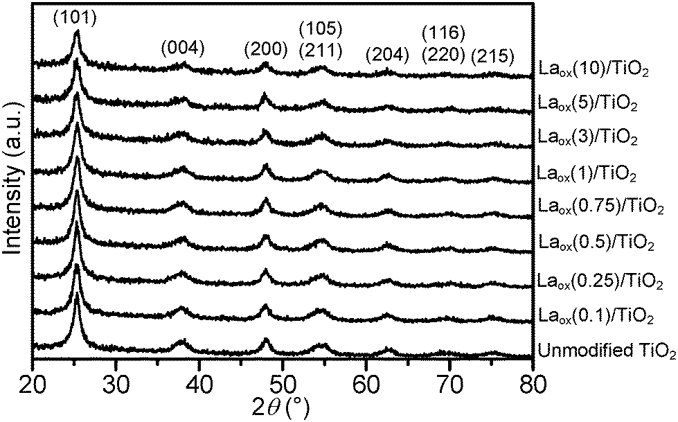 | ||
| Fig. 1 Powder XRD patterns of the unmodified and La-modified TiO2 samples. | ||
The average TiO2 crystallite size of the samples was estimated based on the Scherrer equation with a line width analysis of the anatase (101) diffraction peak and the values are shown in Table 1. It can be seen from Table 1 that the crystallite size of the unmodified TiO2 and Laox/TiO2 samples was in the range of 8 to 10 nm. The unaffected crystal phase and crystallite size clearly demonstrated that under the current synthesis conditions, La3+ did not enter the TiO2 crystal lattice to substitute for Ti4+. This was reasonable since the radius of La3+ (1.15 Å) was much larger than that of Ti4+ (0.64 Å).8,23
| Samples | Crystallite sizea (nm) | Amount of loaded Lab (mol%) | Bandgapc (eV) |
|---|---|---|---|
| a Estimated from a full width at half maximum (FWHM) of the XRD anatase (101) reflection by the Scherrer equation. b Estimated from ICP-OES. c Estimated using the Tauc plot of DR UV-vis data. | |||
| Unmodified TiO2 | 9.3 | 0.00 | 3.33 |
| Laox(0.1)/TiO2 | 8.3 | 0.12 | 3.30 |
| Laox(0.25)/TiO2 | 9.9 | 0.22 | 3.28 |
| Laox(0.5)/TiO2 | 8.8 | 0.46 | 3.28 |
| Laox(0.75)/TiO2 | 8.3 | 0.69 | 3.30 |
| Laox(1)/TiO2 | 8.8 | 0.91 | 3.30 |
| Laox(3)/TiO2 | 8.8 | 2.67 | 3.32 |
| Laox(5)/TiO2 | 9.9 | 4.44 | 3.32 |
| Laox(10)/TiO2 | 9.9 | 7.82 | 3.34 |
Table 1 also displays the lanthanum contents of the unmodified TiO2 and Laox/TiO2 samples that were estimated with ICP-OES. For samples with low loadings of La (0.1–5 mol%), the added nominal La loadings were found to be similar to the actual loading measured from ICP-OES. On the other hand, the high loading sample (10 mol%) has a lower measured La content, suggesting that UV lamp exposure might not be sufficiently long to completely deposit all the lanthanum acetylacetonate hydrate precursor.
Shown in Fig. 2(a) are the ultraviolet-visible (UV-vis) absorption spectra of the unmodified TiO2 and the Laox/TiO2 samples. The characteristic band edge for titanium dioxide appeared at about 370 nm, which is associated with the O2−(2p) → Ti4+(3d) charge transfer process and related to electron excitation from the valence band (VB) to the conduction band (CB) of TiO2.41,42 It was obvious that after modifications with lanthanum oxide, TiO2 did not display extended absorption into the visible region in the range of 400 to 800 nm. The bandgap of the samples was estimated by the Tauc plot, [(αhν)1/2versus hν, where α is the absorbance]14,18,39 whereby the extrapolation of the linear part of the curve gives direct values of the bandgap. The Tauc Plots are shown in Fig. 2(b) and the estimated bandgap values are listed in Table 1. The unmodified HK UV100 sample has a bandgap of about 3.33 eV. The lanthanum-modified samples showed a similar bandgap value to the unmodified TiO2, in the range of 3.28–3.34 eV. Since there is no significant shift in the bandgap and no absorption in the visible range, it can be concluded that La3+ ions were not incorporated into the crystal lattice of TiO2. As discussed above, the ionic radius of the La3+ species is too large to substitute for Ti4+ in the lattice of TiO2. Thus, they are considered to be dispersed on the surface of the TiO2 particles.29
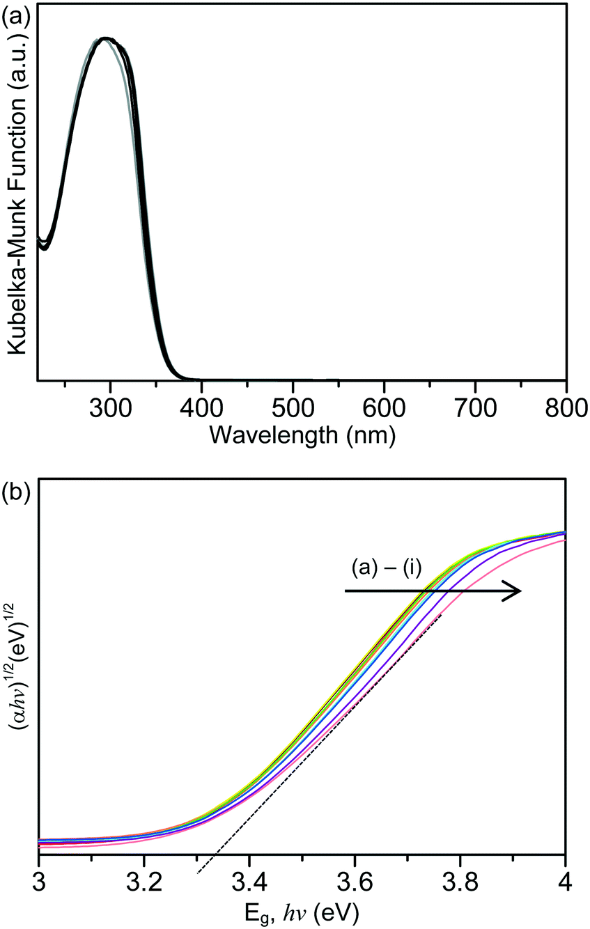 | ||
| Fig. 2 (a) Absorption spectra and (b) Tauc plot of the unmodified and La-modified TiO2 samples. Key: (a) Laox(0.5)/TiO2, (b) Laox(0.25)/TiO2, (c) Laox(0.1)/TiO2, (d) Laox(1)/TiO2, (e) Laox(0.75)/TiO2, (f) Laox(3)/TiO2, (g) Laox(5)/TiO2, (h) Laox(10)/TiO2 and (i) unmodified TiO2. | ||
TEM studies provided some relevant information on the particle size and morphology of the samples. Fig. 3(a) and (b) show representative images obtained from the unmodified TiO2 and Laox(5)/TiO2. In both cases, the samples appeared similar in both size and morphology. No distinct lanthanum oxide particles were observed from the TEM analysis. The La2O3 particles were likely to be highly dispersed on the surface of the TiO2 support. As a result, the La2O3 clusters were too small to be observed, which supported the XRD results.
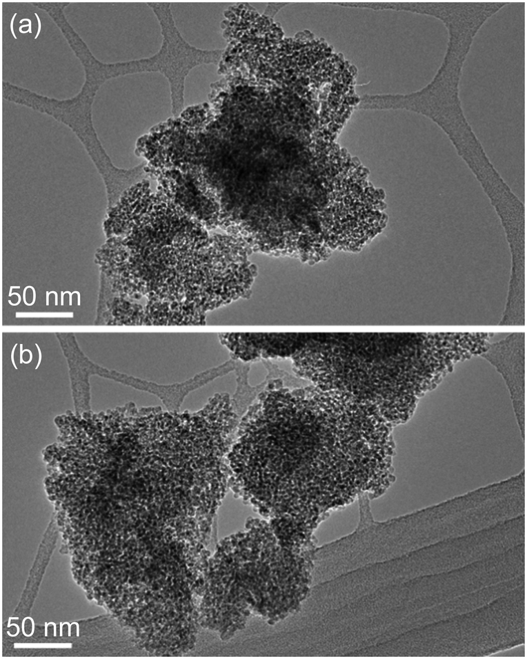 | ||
| Fig. 3 TEM images of (a) unmodified TiO2 and (b) Laox(5)/TiO2 samples. | ||
More detailed information regarding the elemental and chemical states of the unmodified TiO2 and Laox(5)/TiO2 samples was also ascertained by analyzing the X-ray photoelectron spectroscopy (XPS) data. The full scan survey spectra (Fig. 4(a) and (b)) showed that the Ti, O and C elements were present on the surface of the unmodified TiO2 sample, while Ti, O, C and La were identified on the surface of the Laox(5)/TiO2 sample. The C element detected could be ascribed to the adventitious carbon-based compounds, mostly coming from the carbon tape. The high resolution XPS spectra of La 3d, Ti 2p and O 1s are displayed in Fig. 4(c)–(e).
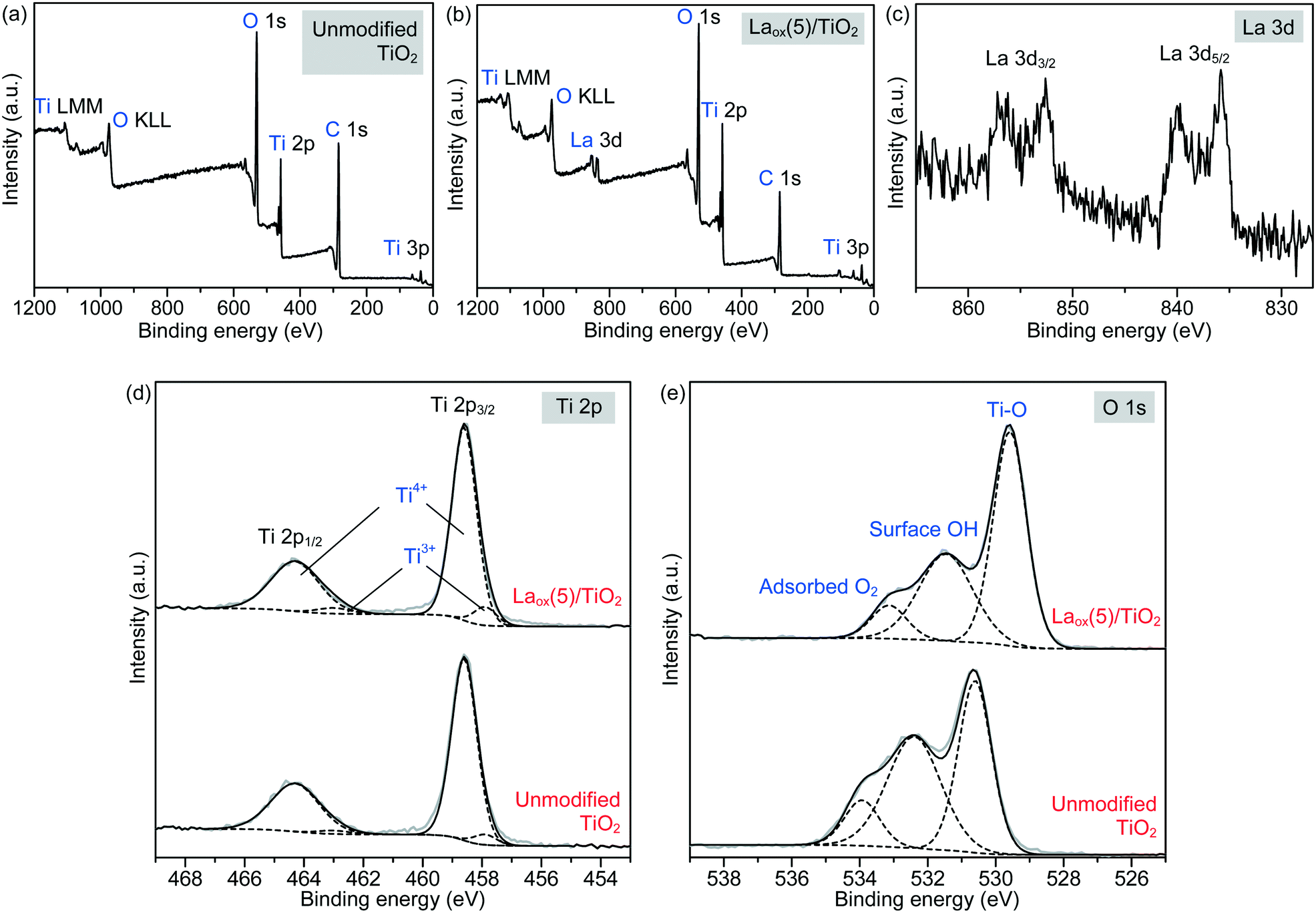 | ||
| Fig. 4 XPS survey spectra of (a) unmodified and (b) Laox(5)/TiO2 samples. The high resolution XPS spectra of the (c) La 3d region, (d) Ti 2p region and (e) O 1s region of the unmodified and Laox(5)/TiO2 samples. Key for (d) and (e): grey solid line = measured data, black solid line = overall model fit, black dashed line = decomposed components. | ||
Regarding the La 3d core level spectra (Fig. 4(c)), a splitting of the La 3d5/2 and La 3d3/2 lines was observed around 834.6 and 851.4 eV, respectively. The peaks at 834.6 and 851.4 eV are identified as the main peaks, and the peaks at 838.8 and 855.6 eV are ascribed to the shake-up satellite peaks of La 3d5/2 and La 3d3/2. As reported in previous works, this La XPS profile indicates the presence of lanthanum oxide species, such as La2O3.15,16,23,24,34,42 In addition to the peak position and splitting, the binding energy difference between the main and satellite peaks (ΔE) in the multiplet split can be used to distinguish La2O3 from other La3+ compounds. It has been reported that the ΔE values for La2O3 are in the range of 3.9–4.5 eV for the La 3d5/2 spectrum.43 The Laox(5)/TiO2 sample gave a ΔE of 4.2 eV, clearly suggesting that the La species in the sample was La2O3. The photodeposition of La2O3 is feasible owing to the oxidative conditions used in this study, as has been also reported to occur in the oxidative photodeposition of Rh2O344 and CuO.40 Since the photodeposition of oxide particles would not occur in the absence of UV light irradiation and oxygen,44 the main species to oxidize the lanthanum precursor to form La2O3 would be the photogenerated oxygen radicals. The proposed reaction is shown in the following equation.
Fig. 4(d) shows the Ti 2p spectrum of the unmodified TiO2 and Laox(5)/TiO2, each consisting of two obvious peaks at about 458.6 and 464.3 eV, which were assigned to Ti2p3/2 and Ti2p1/2, indicating that titanium predominantly existed in the core level in a Ti4+ chemical state. By using the CasaXPS peak fitting program, the XPS peak for Ti2p3/2 was further resolved into two components at binding energies of 458.6 and 457.6 eV, which were ascribed to Ti4+ and Ti3+ species, respectively.9,46 It was obvious that the Ti4+ was the dominant surface state, with a small quantity of Ti3+ states.47 Upon modification with 5 mol% La, the Ti3+ increased by approximately 62% from 4.75 to 7.69%. This result suggests that the presence of La might have led to the additional formation of Ti3+ valence states, in good agreement with previously reported studies.9,16,42
The high resolution XPS O 1s spectra of the unmodified TiO2 and Laox(5)/TiO2 are shown in Fig. 4(e). The wide and asymmetric O 1s spectra indicate that there was more than one component and they could be further decomposed into three peaks, which are the crystal lattice oxygen (OTi–O at 529.6–530.6 eV), surface hydroxyl groups (OO–H at 531.5–532.4 eV) and adsorbed O2 (at 533.2–533.9 eV). The binding energies of these three peaks agree well with reported values in the literatures.9,23,24,46 As shown in Table 2, the surface hydroxyl groups accounted for 45.7% of the total oxygen species on the surface of the unmodified TiO2. After La modification, the proportion of surface hydroxyl groups decreased to 36.0%, which may be due to La being trapped on the surface of TiO2.9,16 Additionally, the O 1s core level peak positions of the La-modified TiO2 was slightly shifted to lower binding energy, indicating the presence of interaction between the La species and TiO2.37
| Catalysts | OTi–O | OO–H | Adsorbed O2 | |||
|---|---|---|---|---|---|---|
| BE (eV) | Area (%) | BE (eV) | Area (%) | BE (eV) | Area (%) | |
| Unmodified TiO2 | 530.6 | 43.6 | 532.4 | 45.7 | 533.9 | 10.7 |
| Laox(5)/TiO2 | 529.6 | 55.0 | 531.5 | 36.0 | 533.2 | 9.0 |
Photocatalytic activity
The photocatalytic activities of the Laox/TiO2 samples were evaluated for 2,4-D-degradation under UV light irradiation as shown in Fig. 5(a). It was confirmed that under the same conditions 2,4-D could not be degraded under UV irradiation in the absence of TiO2 photocatalysts. In the presence of the unmodified TiO2 catalyst, 5.3% of 2,4-D was removed after 1 h UV irradiation. Upon lanthanum modification, all of the TiO2 samples showed improved activity when compared with the unmodified TiO2 catalyst. In particular, the Laox(5)/TiO2 catalyst showed the highest photocatalytic activity, approximately 5.5 times more active than the unmodified TiO2 catalyst. The results indicated that the photocatalytic performance of TiO2 could be significantly enhanced by the presence of lanthanum oxide species. With a La loading above 5 mol%, the decrease of photocatalytic activity might be due to excessive La2O3 covering the surface, which blocked the TiO2 actives sites from UV irradiation. This result agreed well with previously reported works7–10,12,13 and similar to the masking effect reported on copper oxide modified TiO2.40 | ||
| Fig. 5 Photocatalytic activities of unmodified and lanthanum-modified TiO2 photocatalysts under (a) UV, (b) visible, and (b) solar simulator light irradiation for 1, 6, and 3 h, respectively. | ||
As shown in Fig. 2, the lack of optical absorption of the La-modified TiO2 photocatalysts in the visible region suggested that La would not assist in improving the visible light absorption of TiO2. The activity of the La-modified samples was further evaluated by conducting visible light activity testing. The results are shown in Fig. 5(b). The unmodified TiO2 led to a 1.2% degradation of 2,4-D after 6 h of irradiation. The low activity observed on the unmodified TiO2 might be originated from defect states that allow for limited visible light activity.40,45 The La-modified samples displayed a very similar activity to the unmodified TiO2, obviously indicating that lanthanum species did not contribute to the visible light activity of TiO2.
The photocatalytic activity of the catalysts was also evaluated under solar simulator irradiation and the results are shown in Fig. 5(c). The solar simulator consists of mostly visible light, with the presence of a small fraction of UV irradiation. Therefore, the activity trend between visible and solar activity shall be similar to each other. As expected, upon modification with various loadings of La, the activity of the Laox/TiO2 remained nearly unchanged as compared with the unmodified TiO2. Further increase of lanthanum loading beyond 1 mol% led to a decrease in photocatalytic activity. These results supported that La modification did not give rise to the enhancement of TiO2 visible light activity. In comparison with previous works that reported the occurrence of visible light activity of La–TiO2 catalysts, the visible light activity was most likely caused by the photosensitization effect, when organic dyes were used as the model pollutants.14,15,19–27
Four recycling runs of the best photocatalyst, the Laox(5)/TiO2 sample, were carried out to investigate the stability of the photocatalyst. The reactions were each carried out under UV light for 6 h. As shown in Fig. 6, the regenerated photocatalyst exhibited good performance and stability. Over all four cycles, the degradation rate of 2,4-D remained almost unchanged compared to the fresh photocatalyst. The consistent photocatalytic performance indicated that the photocatalyst has an excellent long-term stability and good potential for wastewater treatment applications.
 | ||
| Fig. 6 Recycling tests on the Laox(5)/TiO2 sample for photocatalytic degradation of 2,4-D under UV light for 6 h. | ||
The charge separation and transportation characteristics of the unmodified TiO2 and the best photocatalyst were investigated with EIS. The typical EIS spectra of the unmodified TiO2 and the Laox(5)/TiO2 were presented as Nyquist plots and simulated with the equivalent circuit. As shown in Fig. 7(a), each sample exhibited a partial semicircle at the high-frequency region of the EIS measurement. Upon the introduction of lanthanum species, the diameter of the semicircle in the plot became smaller, which indicated a decrease in the charge transfer resistance on the TiO2 surface.23 Furthermore, model fitting (with the constant phase element (CPE) with a diffusion model) revealed a lower charge transfer resistance value of the Laox(5)/TiO2 sample (2.65 kΩ) as compared to the unmodified TiO2 sample (3.66 kΩ). The significant decrease in the electron-transfer resistance in the presence of lanthanum species resulted in an effective charge transfer and separation of TiO2, leading to an enhanced photocatalytic degradation of the 2,4-D pollutant.
 | ||
| Fig. 7 (a) Nyquist plots (solid circles and squares) of the EIS changes of the unmodified TiO2 and Laox(5)/TiO2 samples, with the corresponding circuit model fits (line). The EIS measurements were performed in the presence of 2.5 mM K3[Fe(CN)6] in 0.1 M Na2SO4 aqueous solution. Inset: Equivalent circuit for fitting the charge transfer impedance of the photocatalysts, where Cdl = double layer capacitance, Rs = solution resistance, Rct = charge transfer resistance and W = Warburg impedance. (b) Photocurrent vs. time response of the unmodified TiO2 and Laox(5)/TiO2 samples measured under pulsed UV light illumination in Na2SO4 (0.1 M) electrolyte vs. Ag/AgCl reference electrode at an applied potential of 0 V. | ||
In order to investigate the effect of lanthanum modification on the photo-electrochemical properties of the resulting La–TiO2 composites, measurements of the time-dependent photocurrent response were performed. As shown in Fig. 7(b), anodic (positive) photocurrent responses indicate that the samples exhibited n-type semiconductor characteristics under UV light illumination. The photocurrent traces of the unmodified TiO2 and Laox(5)/TiO2 showed a rapid response and good reproducibility at each of the turn-on and turn-off instances. In the absence of applied biased potential, the photoelectrodes of the Laox(5)/TiO2 photocatalyst generated a significantly higher photocurrent density than the photocurrent of the unmodified TiO2 photoelectrode. These results further confirm the ability of the La species to improve the separation of photogenerated electron–hole pairs.37,48
Proposed mechanism
Based on the results shown above, a mechanism for the role of lanthanum species in enhancing the activity of TiO2 under UV irradiation is proposed and depicted in Fig. 8. As shown in Fig. 8, there are three possible pathways of electron transfer in the photocatalytic system, denoted as P1, P2 and P3, respectively. The first pathway (P1) involves the conventional bandgap transition of TiO2. When illuminated, the electrons in the VB of TiO2 were excited to the CB, leaving holes in the VB. The excited electrons could then react with adsorbed oxygen to form superoxide radicals. Due to the short lifetime of the photogenerated electron–hole pairs, they normally tend to recombine quickly.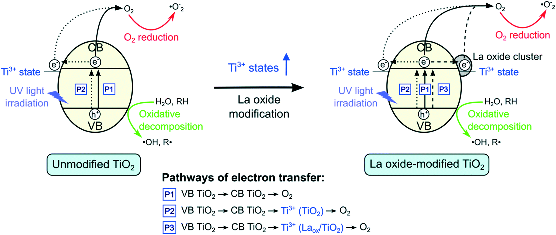 | ||
| Fig. 8 Proposed mechanisms on the lanthanum-modified TiO2 under UV light irradiation. | ||
As shown by the XPS results, in addition to the dominant Ti4+ states, there is also a small proportion of Ti3+ species present in the unmodified TiO2. When the TiO2 is excited, the electrons in the VB could be transferred to the 3d states of Ti3+. The Ti3+ species that have accepted the electrons could then transfer the electrons to form other active species, such as superoxide anions (˙O−2) and hydroxyl radicals (˙OH),10–12,26,34 which could further degrade the 2,4-D molecules. Hence, in the absence of lanthanum modifications, this pathway (P2) and the conventional excitation of electrons from VB TiO2 to CB TiO2 (P1) were expected to contribute to the photocatalytic activity of the unmodified TiO2.
The EIS and photocurrent results shown above suggested that in the presence of lanthanum species on the surface of TiO2, the recombination of the electron–hole pairs was reduced, resulting in the improved photocatalytic activity. However, previous reports proposed that the CB edge of La2O3 is located at a far more negative position (∼−1.8 to −3.5 V vs. standard hydrogen electrode (SHE)) than that of anatase TiO2 (∼−0.3 V vs. SHE). Since La2O3 does not possess the suitable potential, electron transfer from the CB edge of TiO2 to La2O3 is not possible.7,9,10 Hence, there might be another species that led to the improved charge separation of TiO2.
From the XRD and DR UV-vis results, it was shown that the crystal structure, crystallite size and bandgap of TiO2 were not significantly affected by the La modification. These suggested that only surface modification took place. At the La2O3 and TiO2 interface, a charge imbalance of TiO2 might be created in the presence of La3+ species. In order to overcome this charge imbalance, Ti4+ is thus reduced to Ti3+.7,9,10,12,14,16,17,33,34,37 In this study, as indicated by the XPS Ti2p analysis, the increase of Ti3+ species on the surface of the TiO2 photocatalysts was attributed to the lanthanum modification. The incorporation of La3+ species led to the formation of additional impurity Ti3+ states that resulted in the increased charge transfer and separation. Therefore, upon modification with lanthanum species, there is an additional pathway (P3) where electrons could be captured. As such, lanthanum modified TiO2 photocatalysts showed decreased charge recombination, leading to the increased photocatalytic activity. However, if the amount of Ti3+ was too high, it might act to promote electron–hole recombination.7,9,10,12 Therefore, the optimum amount of La2O3 that gave the optimum photocatalytic performance under UV light irradiation could be also related to the optimum amount of Ti3+.
Conclusions
Lanthanum oxide was successfully loaded onto the surface of HK UV100 TiO2 by a photodeposition method, which did not require any heat treatment processes. This method resulted in the formation of highly dispersed La(III) oxide species on the TiO2 surface, and it did not alter the crystallite size and the phase structure of TiO2. The photocatalytic activity testing under UV irradiation showed a notable improvement of La-modified TiO2 photocatalytic activity over the unmodified TiO2 up to 5.5 times at 5 mol% La loading. The added lanthanum species was proposed to create additional Ti3+ states that improved the charge separation of TiO2. Recycling tests confirmed that the Laox(5)/TiO2 catalyst showed good stability. On the other hand, when under visible or solar simulator irradiation, there was no significant improvement of photocatalytic activity of the Laox/TiO2 catalysts as compared to the unmodified TiO2. This observation confirmed that the lanthanum species did not contribute to the visible light activity of TiO2 under visible or solar irradiation conditions.Acknowledgements
The research leading to these results has received funding from the European Union Seventh Framework Program (EU-FP7) under the 4G-PHOTOCAT grant (agreement no.: 309636). This work has been also financially supported by the Ministry of Higher Education (MOHE) and Universiti Teknologi Malaysia (UTM, Malaysia) through the international contract matching grant (cost center code: R.J130000.7626.4C035).References
- S. Gupta and M. Tripathi, Chin. Sci. Bull., 2011, 56, 1639 CrossRef CAS.
- M. I. Litter, Appl. Catal., B, 1999, 23, 89 CrossRef CAS.
- C. M. Teh and A. R. Mohamed, J. Alloys Compd., 2011, 509, 1648 CrossRef CAS.
- S. G. Kumar and L. G. Devi, J. Phys. Chem. A, 2011, 115, 13211 CrossRef CAS PubMed.
- S. Bingham and W. A. Daoud, J. Mater. Chem., 2011, 21, 2041 RSC.
- H. Liu, L. Yu, W. Chen and Y. Li, J. Nanomater., 2012, 2012, 1 Search PubMed.
- X. Quan, H. Tan, Q. Zhao and X. Sang, J. Mater. Sci., 2007, 42, 6287 CrossRef CAS.
- L. Jing, X. Sun, B. Xin, B. Wang, W. Cai and H. Fu, J. Solid State Chem., 2004, 177, 3375 CrossRef CAS.
- F. B. Li, X. Z. Li and M. F. Hou, Appl. Catal., B, 2004, 48, 185 CrossRef CAS.
- F. B. Li, X. Z. Li, C. H. Ao, S. C. Lee and M. F. Hou, Chemosphere, 2005, 59, 787 CrossRef CAS PubMed.
- S. Anandan, Y. Ikuma and V. Murugesan, Int. J. Photoenergy, 2012, 921412 Search PubMed.
- S. Yuan, Q. Sheng, J. Zhang, F. Chen, M. Anpo and Q. Zhang, Microporous Mesoporous Mater., 2005, 79, 93 CrossRef CAS.
- L. Xing, J. Jia, Y. Wang and S. Dong, Environ. Prog. Sustainable Energy, 2013, 32, 302 CrossRef CAS.
- X. Chen, H. Cai, Q. Tang, Y. Yang and B. He, J. Mater. Sci., 2014, 49, 3371 CrossRef CAS.
- Q. Wang, S. Xu and F. Shen, Appl. Surf. Sci., 2011, 257, 7671 CrossRef CAS.
- Z. He, X. Xu, S. Song, L. Xie, J. Tu, J. Chen and B. Yan, J. Phys. Chem. C, 2008, 112, 16431 CAS.
- G. Cao, Y. Li, Q. Zhang and H. Wang, J. Hazard. Mater., 2010, 178, 440 CrossRef CAS PubMed.
- J. Li, B. Li, J. Li, J. Liu, L. Wang, H. Zhang, Z. Zhang and B. Zhao, J. Ind. Eng. Chem., 2015, 25, 16 CrossRef CAS.
- M. M. Haque, W. Raza, M. Muneer, M. Fleisch, A. Hakki and D. Bahnemann, J. Alloys Compd., 2015, 632, 837 CrossRef.
- Y. Cong, B. Tian and J. Zhang, Appl. Catal., B, 2011, 101, 376 CrossRef CAS.
- K. Umar, M. M. Haque, M. Muneer, T. Harada and M. Matsumura, J. Alloys Compd., 2013, 578, 341 CrossRef.
- V. Štengl, S. Bakardjieva and N. Murafa, Mater. Chem. Phys., 2009, 114, 217 CrossRef.
- L.-L. Long, A.-Y. Zhang, J. Yang, X. Zhang and H.-Q. Yu, ACS Appl. Mater. Interfaces, 2014, 6, 16712 CAS.
- N. R. Khalid, E. Ahmed, Z. Hong and M. Ahmad, Appl. Surf. Sci., 2012, 263, 254 CrossRef CAS.
- L. Gao, H. Liu and J. Sun, Mater. Sci. Forum, 2005, 486–487, 53 CrossRef CAS.
- Z. Song, X. Sun and J. Qiu, Indian J. Chem., Sect. A: Inorg., Bio-inorg., Phys., Theor. Anal. Chem., 2014, 53, 1332 Search PubMed.
- M.-Y. Xing, D.-Y. Qi, J.-L. Zhang and F. Chen, Chem. – Eur. J., 2011, 17, 11432 CrossRef CAS PubMed.
- L. Zong, Q. Li, J. Zhang, X. Wang and J. Yang, J. Nanopart. Res., 2013, 15, 1 Search PubMed.
- J. Choi, H. Park and M. R. Hoffmann, J. Phys. Chem. C, 2009, 114, 783 Search PubMed.
- Y. Wang, L. Jiang and C. Feng, Desalin. Water Treat., 2013, 52, 4802 CrossRef.
- T. Morikawa, Y. Irokawa and T. Ohwaki, Appl. Catal., A, 2006, 314, 123 CrossRef CAS.
- E. P. Reddy, B. Sun and P. G. Smirniotis, J. Phys. Chem. B, 2004, 108, 17198 CrossRef CAS.
- Y. Liu, S. Zhou, J. Li, Y. Wang, G. Jiang, Z. Zhao, B. Liu, X. Gong, A. Duan, J. Liu, Y. Wei and L. Zhang, Appl. Catal., B, 2015, 168–169, 125 CrossRef CAS.
- G. D. Turhan and Ö. E. Kartal, Nanomater. Energy, 2013, 2, 148 CrossRef CAS.
- S. Moradi, M. Vossoughi, M. Feilizadeh, S. M. Zakeri, M. Mohammadi, D. Rashtchian and A. Yoosefi Booshehri, Res. Chem. Intermed., 2014, 41, 4151 CrossRef.
- C. Wen, H. Deng, J.-Y. Tian and J.-M. Zhang, Trans. Nonferrous Met. Soc. China, 2006, 16(Supplement 2), s728 CrossRef.
- J. Nie, Y. Mo, B. Zheng, H. Yuan and D. Xiao, Electrochim. Acta, 2013, 90, 589 CrossRef CAS.
- K. M. Parida and N. Sahu, J. Mol. Catal. A: Chem., 2008, 287, 151 CrossRef CAS.
- C. Hua, X. Dong, X. Wang, M. Xue, X. Zhang and H. Ma, J. Nanomater., 2014, 943796 Search PubMed.
- W. R. Siah, H. O. Lintang, M. Shamsuddin, H. Yoshida and L. Yuliati, Catal. Sci. Technol., 2016, 6, 5079 CAS.
- S. Ghasemi, S. Rahimnejad, S. R. Setayesh, S. Rohani and M. R. Gholami, J. Hazard. Mater., 2009, 172, 1573 CrossRef CAS PubMed.
- A. M. Ruiz, A. Cornet and J. R. Morante, Sens. Actuators, B, 2005, 111–112, 7 CAS.
- S. Mickevičius, S. Grebinskij, V. Bondarenka, B. Vengalis, K. Šliužienė, B. A. Orlowski, V. Osinniy and W. Drube, J. Alloys Compd., 2006, 423, 107 CrossRef.
- K. Shimura, H. Kawai, T. Yoshida and H. Yoshida, ACS Catal., 2012, 2, 2164 Search PubMed.
- I. N. Martyanov, S. Uma, S. Rodrigues and K. J. Klabunde, Chem. Commun., 2004, 2476 RSC.
- C. Su, L. Liu, M. Zhang, Y. Zhang and C. Shao, CrystEngComm, 2012, 14, 3989 RSC.
- X. Liu, S. Gao, H. Xu, Z. Lou, W. Wang, B. Huang and Y. Dai, Nanoscale, 2013, 5, 1870 RSC.
- Y. Wang, H. Cheng, Y. Hao, J. Ma, W. Li and S. Cai, Thin Solid Films, 1999, 349, 120 CrossRef CAS.
| This journal is © The Royal Society of Chemistry 2017 |