
Oxygen vacancies at the Au/SrTiO3(001) interface: stabilities, electronic properties and effect on photocatalysis†
Xiangchao
Ma
ab,
Ying
Dai
*a,
Mengmeng
Li
a and
Baibiao
Huang
a
aSchool of Physics, State Key Laboratory of Crystal Materials, Shandong University, Jinan 250100, China. E-mail: daiy60@sina.com
bSchool of Physics and Optoelectronic Engineering, Xidian University, Xi'an, 710071, China
First published on 23rd November 2016
Abstract
Oxygen vacancies have proven to induce various and important effects on the properties of materials. In the present work, the thermodynamic stabilities and electronic properties of oxygen vacancies (Ov) on the SrTiO3 (STO)(001) surface and at the Au/STO(001) interface are systematically investigated by means of first-principles calculations. Both the SrO and TiO2 terminated (001) surfaces of STO are examined. It is found that the Ov located in the near-surface region of the two surfaces can be divided into three categories according to their properties: Ov in the surface atomic layer, Ov in the subsurface TiO2 atomic layers, and Ov in the subsurface SrO atomic layers. Counter-intuitively, for the SrO terminated surface the most stable site of Ov is in the first subsurface atomic layer. The Au metal in the Au/STO heterostructure significantly promotes the formation of Ov at and near the interface and thermodynamically promotes migration of Ov to the interfacial atomic layer. Furthermore, the interface Schottky barrier height is highly sensitive to both the concentration and position of Ov at the interface. These results are beneficial for the atomic-level understanding of the performance of STO-based photocatalysts and the rational design of more efficient ones.
Introduction
The intrinsic defects of a material not only affect its properties, but also introduce new physics for it. This is especially prominent for perovskite SrTiO3 (STO), in which oxygen vacancies (Ov) have proven to induce various effects, such as n-type conductivity,1 and green and blue light emission.2,3 In the photocatalytic applications of STO, the surface region Ov have also proven to extend light absorption,4 and facilitate the adsorption and dissociation of water molecules.5 However, understanding about the roles of Ov in enhancing the photocatalytic activity is still very limited. In particular, the thermodynamic stabilities of Ov in the STO surface region, which determine the distribution of Ov in the surface region and thus the surface physicochemical properties, are not well studied. Considering the difference in the thermodynamic stabilities of Ov in the STO bulk region and in the STO(001) surface atomic layer,6 it is generally believed that the introduced Ov will mostly migrate to and locate at the (001) surface atomic layer.7–9 However, the detailed stabilities of Ov in several atomic layers near the surface are more essential in determining the specific migration and location of Ov, which have not yet been well established. To the best of our knowledge, only Silva et al. (2014) reported some preliminary information about the stabilities of Ov in several atomic layers near the STO(001) surface.10 However, the possible effects of Ov induced oxygen-octahedron rotation (OOR), whose importance in the electronic structures of Ov in bulk STO has recently been noted,11 on the stability of Ov is not included in the results.On the other hand, a combination of STO with metal often leads to more versatile applications in (photo)catalysis12–14 and electronics.15,16 For example, Au nanoparticles can often function as ‘charge sinks’ that accumulate electrons17 or holes18 in Au loaded STO photocatalysts, thus promoting charge transfer and electron–hole separation. Moreover, Au nanoparticles of the appropriate size exhibit localized surface plasmon resonance,19 which can generate hot electrons that may transfer into the conduction band of STO and further induce photocatalytic reactions.20,21 As can be seen, most of the functionalities of Au/STO composites involve charge transfer between Au and STO, which highly affects their overall performance and is dominated mainly by the interfacial Schottky barrier in the metal–semiconductor contact.22,23 Therefore, we also investigate if the addition of Au affects the properties of Ov on the original STO surface and if Ov in turn affects the interfacial conductivity. Experimentally, Bonnell et al. (2015) reported that in the Au/STO(001) heterostructure, Ov spontaneously migrate from STO to the interface upon annealing and the interfacial electronic conductivity is concomitantly enhanced,24 suggesting the effect of Ov on the interfacial electronic properties. Very recently, dependence of the photocatalytic activity of Au/STO on Ov was also demonstrated experimentally.25
In this work, we investigate Ov in the several atomic layers near STO(001) surfaces and Au/STO(001) interfaces, focusing on their thermodynamic stabilities and electronic properties. For the first time, we demonstrate the significant ability of OOR to stabilize the geometric and electronic structures of Ov on the surfaces and at the interfaces. Counter-intuitively, we find that for the SrO terminated surface the most stable Ov location is in the subsurface atomic layer. Au metal substantially changes the thermodynamic stabilities of Ov in the original surface region of STO. Moreover, both the concentration and position of Ov at the interface considerably modulate the interface SBH, which presents a new degree of freedom for optimizing the charge transfer between Au and STO.
Computational methods
The first-principles calculations are based on the density functional theory (DFT), as implemented in the Vienna Ab initio Simulation Package code.26 The ionic potentials are described using the projector augmented wave (PAW) method27,28 within the local density approximation (LDA). Provided that the LDA functional cannot accurately describe the exchange and correlation interactions of d electrons in STO, we adopt the LDA+U method with a rotationally invariant approach,29 where the effective Hubbard-U for the Ti 3d orbital is Ueff = U − J = 4.36 eV.30 For the Au 5d orbital the Hubbard-U correction is not applied because the LDA functional can correctly describe the properties of Au with which we are concerned.31 The plane-wave cutoff energy is 450 eV. The Brillouin zones of the STO primitive cell, 2 × 2 × 12 and 4 × 4 × 3 STO(001) surface supercells, and the Au/STO(001) interface are sampled with 8 × 8 × 8, 3 × 3 × 1, 2 × 2 × 1, and 3 × 3 × 1 Γ-centered k-points, respectively. For structural optimizations, the in-plane lattice parameters of STO are fixed to the calculated values for bulk STO (a = 3.9 Å), the atomic positions are then fully relaxed until the residual Hellmann–Feynman forces become smaller than 0.02 eV Å−1. Note that the effects of supercell size and lattice relaxation on the Ov formation energy have been tested. As listed in Table S1 (ESI†), the difference in the Ov formation energy calculated with 2 × 2 × 2 and 3 × 3 × 3 supercells is rather small with a value of about 0.1 eV, and the effect of lattice relaxation is negligible. Therefore, the 2 × 2 supercell without lattice relaxation is used considering the computational load of the large surface models. In addition, the Ov concentration is generally high in the surface region of STO, which may be more appropriately described by the smaller 2 × 2 supercell.The formation energy of Ov [Ef(Ov)] is defined as

Results and discussion
Supercell models
Fig. 1 shows the models for simulating STO(001) surfaces and Au/STO(001) interfaces. The STO(001) surfaces are represented by mirror-symmetrical 2 × 2 × 12 supercell slabs. The Au/STO(001) interfaces are also kept mirror-symmetrical by depositing five Au atomic layers on both sides of the surface slabs. Moreover, both the surface and interface slabs are separated by a vacuum larger than 15 Å. On the basis of previous results,24,33,34 we adopt the energetically most favorable on-top adsorption geometries of Au on STO(001) surfaces: for the SrO terminated surface, Au atoms are on top of both O and Sr atoms; for the TiO2 terminated surface, Au atoms are solely on top of O atoms. In each Ov doped model, two Ov are introduced by removing two O atoms from two symmetrical atomic layers (one Ov for each atomic layer) that are parallel to the surface or the interface. The Ov doped model thus created is denoted by the label for the atomic layer in which Ov are located, as shown in Fig. 1. | ||
| Fig. 1 Optimized perfect supercell models. (a) SrO and (b) TiO2 terminated STO(001) surfaces. (c) SrO and (d) TiO2 terminated Au/STO(001) interfaces. In each model the labels for some atomic layers are written on their right. For each mirror-symmetrical model, only half of it is shown. | ||
Stabilities of Ov on STO(001) surfaces
First, the surface Ov formation energies with respect to the bulk are calculated. As listed in Table 1, Ov are more stable on the TiO2 terminated surface than on the SrO terminated surface. This relative stability of Ov on the two surfaces is consistent with previous calculations;7,35 the difference in the specific values is mainly because the used exchange–correlation functionals and/or supercells are different.To illustrate the thermodynamic stabilities of Ov on the surface, we calculate the formation energy of Ov [Ef(Ov)] with respect to the distance from the surface. Fig. 2(a) shows the calculated results for the SrO terminated surface. Overall, the stabilities of Ov near this surface are divided into three categories: (1) Ov in the surface SrO layer, whose formation energy is smaller than those of Ov in the subsurface SrO layers by about 0.5 eV; (2) Ov in the subsurface TiO2 layers, which are thermodynamically the most stable among the three categories; (3) Ov in the subsurface SrO layers, which are the least stable. In addition, the stabilities of Ov in both category (2) and (3) show no considerable dependence on the distance from the surface, and their stabilities have already converged when Ov are in the first subsurface TiO2 [for category (2)] or SrO [for category (3)] layer. These results suggest that Ov will be transferred to the adjacent TiO2 layers if they are initially introduced into the subsurface SrO layers. This is also true even for Ov in the surface SrO layer. Therefore, for the SrO terminated surface it will be very easy to generate Ov in the first subsurface TiO2 layer. Indeed, this has been experimentally observed by Iwaya et al.36 These results indicate that Ov in the first subsurface TiO2 layer should also be paid enough attention in order to fully understanding the properties of the SrO terminated surface.
 | ||
| Fig. 2 Formation energy of Ov [Ef(Ov)] as a function of the distance from the surface. The location of Ov is denoted by the label for the atomic layer in which it is located. (a) SrO terminated surface. (b) TiO2 terminated surface. For each surface, Ef(Ov) is given with respect to that of Ov in the surface atomic layer, which is set to 0 eV. | ||
The stabilities of Ov on the TiO2 terminated surface are very similar to those on the SrO terminated surface [Fig. 2(b)], except that Ov in the surface TiO2 layer are now the most stable and the stabilities of Ov in the subsurface SrO layers start to converge in the second subsurface SrO layer. The highest stability of Ov in the surface TiO2 layer means that the experimentally introduced Ov are generally located in this surface atomic layer. In addition, we have also investigated the stabilities of Ov in the surface and the first subsurface atomic layers of the two terminated surfaces using much larger 4 × 4 supercell slabs. The results are consistent with those found when using the 2 × 2 supercell. The different stabilities of Ov near the SrO and TiO2 terminated surfaces are probably linked to their distinct physics.7
To understand the stabilities of Ov shown above, we examine both geometric and electronic structures for Ov doping models. The geometric structures for some models of Ov doping on the SrO terminated surface are shown in Fig. 3(a). In comparison to the perfect surface [Fig. 1(a)], Ov doping in the SrO layers induces no considerable structural relaxations [S1 and S3 in Fig. 3(a)]. In contrast, Ov doping in the TiO2 layers induce a significant anti-ferrodistortive like OOR throughout the supercell [S2 in Fig. 3(a)]. In our calculations by using 4 × 4 × 3 supercell slabs, we also observed the same changes in the geometric structures. A similar OOR has been experimentally revealed37 and predicted theoretically on the STO(001) surface.38 In 2013, Choi et al. also demonstrated the importance of the Ov induced OOR in establishing the physics of Ov in bulk STO.11 However, its possible effect on the stabilities of Ov on the STO(001) surface has not yet been investigated. As a crude estimation, we compare the total energy of a supercell slab with the OOR with that without the OOR (both of the supercell slabs contain no Ov). The former is shown to be more stable than the latter by about 0.8 eV, which means that the OOR can help stabilize Ov.
 | ||
| Fig. 3 (a) Optimized geometric structures and (b) density of states (DOS) for the SrO terminated surfaces with Ov in the S1, S2, and S3 atomic layers. The geometric structures and DOS for the other surfaces with Ov in much inner SrO and TiO2 layers are similar to the results for Ov in the S3 and S2 atomic layers, respectively. The dashed red line represents the Fermi level. | ||
The OOR can also stabilize the electronic structures of Ov. As shown in Fig. 3(b), the electrons donated by Ov in the S2 model are located rather below the conduction band edge (CBE), whereas those in the S1 and S3 models are located just at or near the CBE. Therefore, we conclude that the Ov induced OOR is the primary reason for the much larger stabilities of Ov in the TiO2 layers. On the other hand, because the geometric and electronic structures of S1 and S3 are quite similar, the lower formation energy of Ov in the S1 model as compared with the S3 model is mainly due to the reduced Madelung potential and coordination atoms at the surface.
For the TiO2 terminated surface, the OOR is also induced only when Ov are located in the TiO2 layers [Fig. S1(a), ESI†], which stabilizes both geometric and electronic structures of the Ov [Fig. S1(b), ESI†]. Here, a prominent characteristic is that two beneficial factors for stabilizing the Ov in the surface TiO2 layer coexist: (i) the OOR rotation; and (ii) the reduced Madelung potential and coordination atoms. Thus, the Ov in the T1 model are the most stable. As for why the Ov in the T2 model are more stable than those in the inner atomic layers, despite the fact that the OOR is not induced, may be understood as follows. As shown in Fig. 4, one of the surrounding Ti atoms of Ov in the T2 model is in the surface atomic layer, which has a larger freedom of relaxation and reduced coordination atoms and consequently much lower d orbital energy. Therefore, the donated electrons by the Ov mostly distribute on this surface Ti atom (Fig. 4), which helps to stabilize the Ov in the T2 model.
 | ||
| Fig. 4 Three-dimensional contour plot of the Ov introduced charge on the TiO2 terminated surface with Ov in the T2 atomic layer. The isosurface value is at 0.005 e Å−3. | ||
On the other hand, from Fig. 2 one may note that the Ef(Ov) does not show saturation and converge to a bulk value. This is because, as shown above, only Ov in the TiO2 atomic layer can induce OOR, whereas the Ov in the SrO atomic layer cannot in the surface models; and this difference can extend to several times the lattice parameter of the STO unit. This is consistent with the previous finding that the Ov induced OOR can extend to more than four times the lattice parameter of the STO unit.11 Furthermore, our results demonstrate that the existence of the surface significantly affects the occurrence of Ov induced OOR.
Stabilities of Ov at the Au/STO(001) interfaces
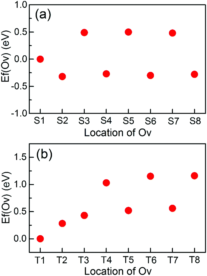
Likewise, we calculate the Ef(Ov) with respect to the distance from the interface to quantify the stabilities of Ov at the Au/STO(001) interface. In comparison with that on the SrO terminated surface, two significant changes in the stabilities of Ov occur at the SrO terminated interface [Fig. 5(a)]: (1) the Ov located in the interfacial SrO layer becomes the most stable; (2) an energy gradient appears in the Ef(Ov) of Ov in the subsurface SrO and TiO2 layers, respectively. These results suggest that the formation of Ov in the interfacial SrO layer is the easiest. Moreover, when an Ov is introduced in the subsurface inner TiO2 or SrO layers, it will experience a thermodynamic driving force promoting its flow to the interfacial region. These implications agree with the recent experiential observation that Ov moves spontaneously to and piles up in the interfacial region of the Au/STO(001) interface upon annealing.24 In addition, the Ef(Ov) of Ov in all the atomic layers is diminished by the addition of Au metal [Fig. 5(b)], indicating that Ov can be more easily introduced at the interface than in the surface system. Furthermore, this reduction in Ef(Ov) decreases as the location of Ov becomes more distant from the interface and is slightly more prominent for Ov in the SrO layers than in the inner adjacent TiO2 layers, suggesting a stronger effect on the SrO layers. | ||
| Fig. 5 E f(Ov) of Ov in the interface system and the reduction in the Ef(Ov) of Ov in the interface system as compared with those in the corresponding surface system. The location of Ov is denoted by the label for the atomic layer in which it is located. (a) and (b) are for the SrO terminated interface. (c) and (d) are for the TiO2 terminated interface. In (a and c), Ef(Ov) are given relative to the formation energy of Ov in the respective interfacial atomic layer of STO, which is set to 0 eV. | ||
For the TiO2 terminated interface, energy gradients in the Ef(Ov) of Ov in the subsurface SrO and TiO2 layers are also introduced, respectively [Fig. 5(c)]. Moreover, the stability of Ov in the interfacial TiO2 layer is much further increased as compared with that in the subsurface atomic layers. The overall trend for the reduction in Ef(Ov), as shown in Fig. 5(d), is very similar to those at the SrO terminated interface. However, the value of reduction in Ef(Ov) for Ov in the same distance from the interface is smaller at the TiO2 terminated interface than at the SrO terminated interface. In the following, we will systematically explain why and how these changes are induced by the addition of the Au metal.
We first examine the electronic structures of the perfect Au/STO(001) interface. As shown in Fig. 6(a), at the SrO terminated interface Au1 and IS1 layers hybridize strongly, which changes the centers of gravity of local DOS (LDOS) for the Au1 and IS1 layers. There are similar results for the TiO2 terminated interface [Fig. 6(b)]. The strong hybridization can stabilize the interfacial SrO(TiO2) layer of the corresponding SrO(TiO2) terminated interface, thus decreasing the formation energy of Ov in the atomic layer. The LDOS for subsurface SrO and TiO2 layers converge to their respective bulk values rapidly. From Fig. 6, in the fully converged atomic layer the Fermi level is located approximately 1 eV (0.6 eV) below the CBE for the SrO(TiO2) terminated interface, indicating the Schottky-type contact with a barrier of 1 eV (0.6 eV). As shown in the preceding section, the electrons donated by all the Ov are located near the CBE. Therefore, they transfer into the lower lying unoccupied Au states in the interface system and consequently reduce the formation energy of the Ov. Because the donated electrons are located higher in energy for Ov in the SrO layers than in the TiO2 layers [Fig. 3(b) and Fig. S1(b), ESI†], the energy gain resulting from the charge transfer is more significant and thus leads to a stronger effect of Ov in the SrO layers. In addition, the charge transfer has to overcome a larger Coulomb attraction for Ov in the inner atomic layers, so that the corresponding energy gain decreases. This explains why the effect of Au decays rapidly with Ov being located further away from the interface. On the other hand, the interface SBH is larger for the SrO terminated interface than for the TiO2 terminated interface (1 vs. 0.6 eV). Based on the charge transfer process, this can result in the smaller reduction in the Ef(Ov) of Ov at the TiO2 terminated interface. Overall, we can conclude that because of the Schottky-type contact at the Au/STO(001) interface, the lower lying unoccupied Au states can accommodate the donated electrons by Ov, thus reducing its formation energy.
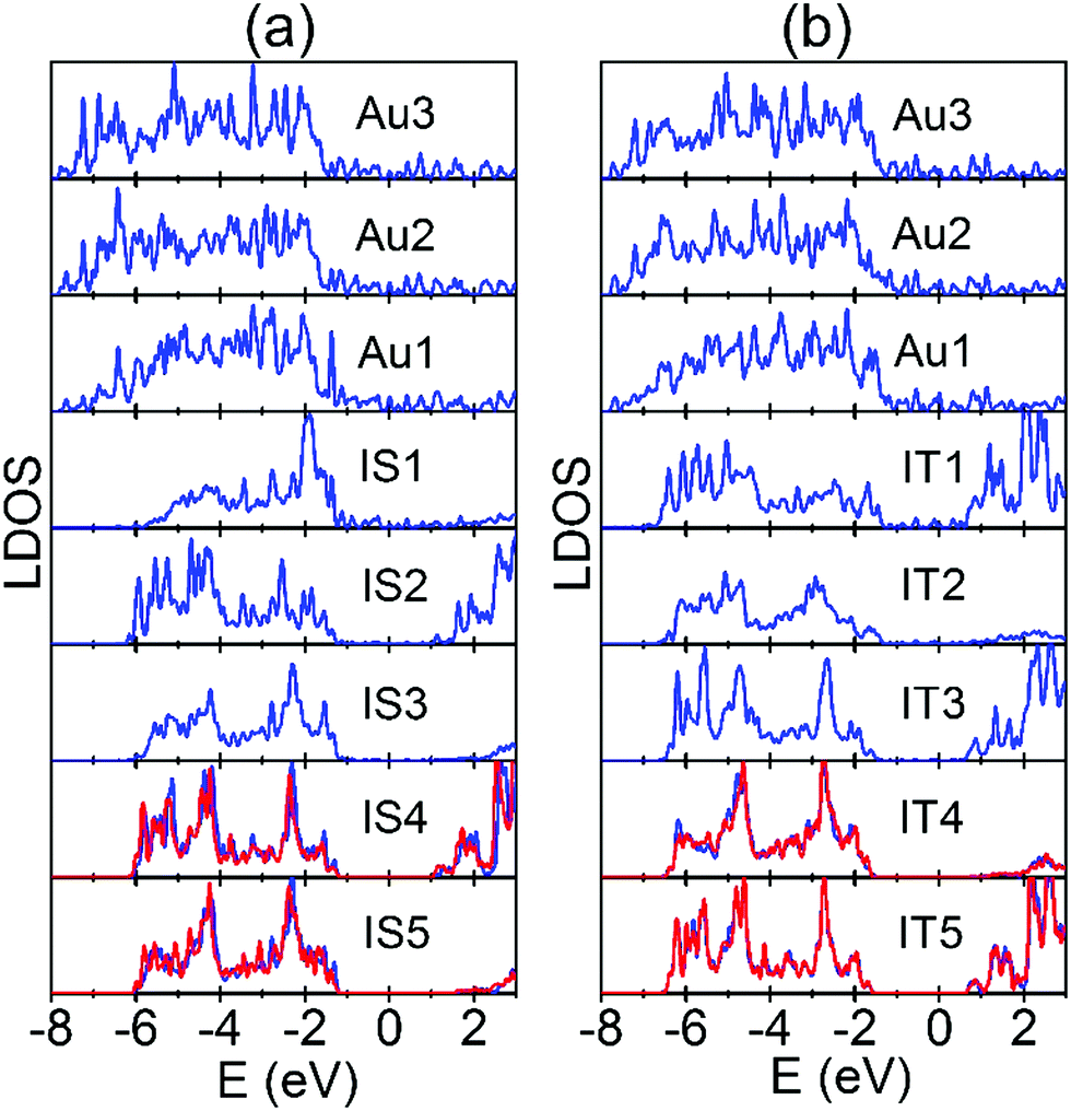 | ||
| Fig. 6 Local density of states (LDOS) for each atomic layer that is parallel to the Au/STO(001) interfaces. (a) SrO terminated interface. (b) TiO2 terminated interface. The labels for atomic layers are the same as in Fig. 1. In each interface, the LDOS of the central bulk region TiO2 and SrO layers are also plotted in red lines for comparison. The Fermi levels of the two interfaces are set to 0 eV. | ||
Effect of the Ov position on the SBH of the Au/STO(001) interfaces
As shown above, Ov will move to and pile up at the Au/STO(001) interface because of the thermodynamic stabilities. Therefore, we investigate the effect of the Ov position near the interface and Ov concentration at the interface on the SBH of the Au/STO(001) interfaces. Here SBH is determined using the general LDOS method,39,40 in which the n-type SBH is the value of the CBE for the bulk region STO measured relative to the Fermi level of the interface system. For simplicity, only the LDOS for the converged bulk region TiO2 layers are shown in Fig. 7, and the determined values of the SBHs are listed in Table S2 (ESI†). For the SrO terminated interface, the SBH is significantly reduced when an Ov is introduced in the STO, and the reduction increases progressively with increasing distance of Ov from the interface [Fig. 7(a)]. Surprisingly, the interface SBH for the IS3 model is almost zero, leading to the Ohmic-type contact. A possible explanation for these results is as follows. As demonstrated above, the charge transfer is weaker for Ov doping in the TiO2 layers than in the SrO layers. Thus, it is understandable that a larger reduction in SBH occurs for Ov doping in the SrO layers. On the other hand, in the IS1 model the Au atom that is above the Ov moves out of the Au layer and toward the STO (Fig. S2, ESI†), indicating a tendency of bonding between the Au atom and the Ti atom, which is below the Ov (Fig. S2, ESI†). Therefore, the donated electrons are partially localized between them. In addition, the drop in potential is proportional to the distance of electron transfer, which means that a larger potential drop will take place for the IS3 model than for the IS1 model. These two factors may result in the smallest reduction in SBH for the IS1 model.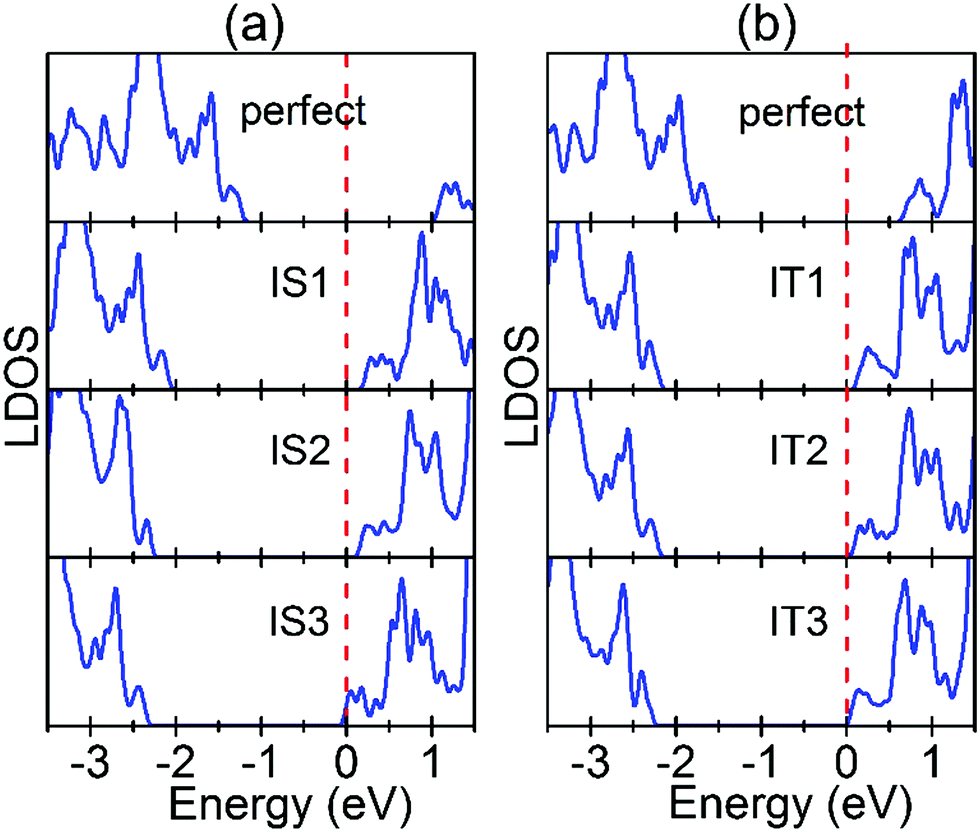 | ||
| Fig. 7 LDOS for the converged TiO2 layer in the interface systems. (a) SrO terminated interfaces: from top to bottom the LDOS are for the TiO2 layer in the 2 × 2 supercell with a perfect interface, an Ov in the IS1 atomic layer, an Ov in the IS2 atomic layer, and an Ov in the IS3 atomic layer, respectively. (b) TiO2 terminated interfaces: from top to bottom the LDOS are for the TiO2 layer in the 2 × 2 supercell with a perfect interface, an Ov in the IT1 atomic layer, an Ov in the IT2 atomic layer, and an Ov in the IT3 atomic layer, respectively. The dashed red lines represent the corresponding Fermi levels. | ||
There are similar changes in SBH for the TiO2 terminated interface [Fig. 7(b)]. An exception is that the reduction in SBH is the largest for the IT3 model. This is probably because the long electron transfer distance in the IT3 model results in a very large potential drop, which over counteracts the weak effect resulting from the relatively small amount of transferred charge. On the other hand, because the original SBH for the perfect Au/STO interface with TiO2 termination is much smaller than that with SrO termination, the interface contact type becomes almost Ohmic-type upon the introduction of Ov in IT1 (the SBH is only about 0.08 eV). Consequently, very small changes in the SBH are needed for the interface to become Ohmic-type in the IT2 and IT3 models, which means that the SBH for the three models should be very similar.
Effect of Ov concentration on the SBH of the Au/STO(001) interfaces
In this section, we investigate if the concentration of Ov at the interface affects the interface SBH. Fig. 8 shows the LDOS for the converged TiO2 layers in the interface systems. As can be seen, for both interfaces the SBH decreases progressively and significantly with increasing Ov concentration. Moreover, the metal–semiconductor contact even becomes Ohmic-type for the fully reduced interfaces. This is primarily because the charge transfer from STO to Au increases with Ov concentration at the interface, which reduces the interfacial potential alignment between Au and STO (Fig. S3, ESI†). This dependence of the interface SBH on the Ov concentration can fully account for the recent experiment that the interfacial electronic conductivity of Au/STO(001) increases with increasing interfacial Ov concentration.24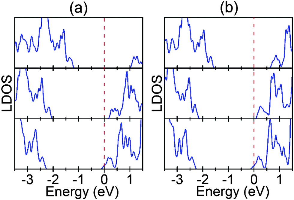 | ||
| Fig. 8 LDOS for the converged TiO2 layers in the interface systems. (a) SrO terminated interface. (b) TiO2 terminated interface. For each interface, from top to bottom the LDOS are for the TiO2 layers in the 2 × 2 supercells with a perfect interface, an Ov at the interface, and the fully reduced interface, respectively. The dashed red lines represent the corresponding Fermi levels. | ||
As stated in the Introduction, for the application of Au sensitized STO in (photo)catalysis, the charge transfer across the metal–semiconductor interface generally dominates the overall system performance. Therefore, the modulation of interface SBH with Ov is also very useful for understanding the performance of the as-prepared samples and the rational design of the high-efficiency system. In addition, for the resistive switching effect in metal/STO devices, it has been proposed that resistive switching is related to the motion of Ov in the near-interface region of STO.41,42 However, because of the difficulty in precisely controlling defects, the detailed mechanism is poorly understood. The presently revealed high sensitivity of the interface SBH to both the position and the concentration of Ov at the Au/STO(001) interface is thus an important contribution for the atomic-level understanding of the resistive switching behavior.
Conclusion
In summary, we have systematically investigated the thermodynamic stabilities and electronic structures of Ov in several atomic layers near STO(001) surfaces and Au/STO(001) interfaces. The main conclusions are summarized as follows.(a) For the TiO2 terminated STO(001) surface the most stable site of Ov is in the surface atomic layer, whereas for the SrO terminated surface it is in the first subsurface atomic layer. This difference may contribute to the diverse physics of the two surfaces. Moreover, in several subsurface atomic layers of the two surfaces, it is thermodynamically much more stable for Ov in the TiO2 layers than in the SrO layers. This is because OOR is induced only when the Ov are located in the TiO2 layers, and the OOR stabilizes both the geometric and electronic structures of the Ov.
(b) At the Au/STO(001) interfaces, the Au metal significantly reduces the formation energies of Ov. Moreover, the Ov that are initially distant from the interface are thermodynamically promoted to move to the interface, leading to piling up of Ov at the interface. This explains the recent experimental observations. In addition, the interface SBH is very sensitive to both the concentration and position of Ov at the interface. By tuning either of the two factors, the contact at the interface can be changed from the Schottky- to Ohmic-type.
These results are beneficial for understanding the phenomena and guiding the rational design of STO related applications. Although for the interface system our investigation is limited to the Au/STO(001) interface, the conclusions are applicable to a much broader collection of metal/STO(001) interfaces.
Acknowledgements
This work was supported by the National Basic Research Program of China (973 program, 2013CB632401), the National Science Foundation of China (grants 11374190 and 21333006), and 111 Project B13029, and the Taishan Scholar Program of Shandong Province.References
- A. Ohtomo and H. Y. Hwang, J. Appl. Phys., 2007, 102, 083704 CrossRef.
- D. Kan, T. Terashima, R. Kanda, A. Masuno, K. Tanaka, S. Chu, H. Kan, A. Ishizumi, Y. Kanemitsu, Y. Shimakawa and M. Takano, Nat. Mater., 2005, 4, 816–819 CrossRef CAS.
- A. Janotti, J. B. Varley, M. Choi and C. G. van de Walle, Phys. Rev. B: Condens. Matter Mater. Phys., 2014, 90, 085202 CrossRef.
- H. Tan, Z. Zhao, W.-B. Zhu, E. N. Coker, B. Li, M. Zheng, W. Yu, H. Fan and Z. Sun, ACS Appl. Mater. Interfaces, 2014, 6, 19184–19190 CAS.
- W. Li, S. Liu, S. Wang, Q. Guo and J. Guo, J. Phys. Chem. C, 2014, 118, 2469–2474 CAS.
- H. L. Zhuang, P. Ganesh, V. R. Cooper, H. Xu and P. R. C. Kent, Phys. Rev. B: Condens. Matter Mater. Phys., 2014, 90, 064106 CrossRef.
- W. Sitaputra, N. Sivadas, M. Skowronski, D. Xiao and R. M. Feenstra, Phys. Rev. B: Condens. Matter Mater. Phys., 2015, 91, 205408 CrossRef.
- A. F. Santander-Syro, O. Copie, T. Kondo, F. Fortuna, S. Pailhes, R. Weht, X. G. Qiu, F. Bertran, A. Nicolaou, A. Taleb-Ibrahimi, P. Le Fevre, G. Herranz, M. Bibes, N. Reyren, Y. Apertet, P. Lecoeur, A. Barthelemy and M. J. Rozenberg, Nature, 2011, 469, 189–193 CrossRef CAS PubMed.
- W. Meevasana, P. D. King, R. H. He, S. K. Mo, M. Hashimoto, A. Tamai, P. Songsiriritthigul, F. Baumberger and Z. X. Shen, Nat. Mater., 2011, 10, 114–118 CrossRef CAS PubMed.
- A. R. Silva and G. M. Dalpian, J. Appl. Phys., 2014, 115, 033710 CrossRef.
- M. Choi, F. Oba, Y. Kumagai and I. Tanaka, Adv. Mater., 2013, 25, 86–90 CrossRef CAS PubMed.
- L. Liu, P. Li, B. Adisak, S. Ouyang, N. Umezawa, J. Ye, R. Kodiyath, T. Tanabe, G. V. Ramesh, S. Ueda and H. Abe, J. Mater. Chem. A, 2014, 2, 9875–9882 CAS.
- S. F. Yuk and A. Asthagiri, J. Chem. Phys., 2015, 142, 124704 CrossRef PubMed.
- W. Wei, Y. Dai, M. Guo and B. Huang, Appl. Surf. Sci., 2011, 257, 6607–6611 CrossRef CAS.
- R. Waser, R. Dittmann, G. Staikov and K. Szot, Adv. Mater., 2009, 21, 2632–2663 CrossRef CAS.
- E. Mikheev, B. D. Hoskins, D. B. Strukov and S. Stemmer, Nat. Commun., 2014, 5, 3990 CAS.
- J. Shi and L. Guo, Prog. Nat. Sci.: Mater. Int., 2012, 22, 592–615 CrossRef.
- Q. Wang, T. Hisatomi, Q. Jia, H. Tokudome, M. Zhong, C. Wang, Z. Pan, T. Takata, M. Nakabayashi, N. Shibata, Y. Li, I. D. Sharp, A. Kudo, T. Yamada and K. Domen, Nat. Mater., 2016, 15, 611–615 CrossRef CAS PubMed.
- X.-C. Ma, Y. Dai, L. Yu and B.-B. Huang, Light: Sci. Appl., 2016, 5, e16017 CrossRef CAS.
- D. Lu, S. Ouyang, H. Xu, D. Li, X. Zhang, Y. Li and J. Ye, ACS Appl. Mater. Interfaces, 2016, 8, 9506–9513 CAS.
- Y. Zhong, K. Ueno, Y. Mori, X. Shi, T. Oshikiri, K. Murakoshi, H. Inoue and H. Misawa, Angew. Chem., Int. Ed., 2014, 53, 10350–10354 CrossRef CAS PubMed.
- X. Ma, Y. Dai, L. Yu and B. Huang, Nanoscale, 2016, 8, 1352–1359 RSC.
- X. Ma, Y. Dai, L. Yu and B. Huang, ACS Appl. Mater. Interfaces, 2014, 6, 12388–12394 CAS.
- W. Qin, J. Hou and D. A. Bonnell, Nano Lett., 2015, 15, 211–217 CrossRef CAS PubMed.
- H. M. Liu, T. Wang, H. B. Zhang, G. G. Liu, P. Li, L. Q. Liu, D. Hao, J. Ren, K. Chang, X. G. Meng, H. M. Wang and J. H. Ye, J. Mater. Chem. A, 2016, 4, 1941–1946 CAS.
- G. Kresse and J. Furthmüller, Comput. Mater. Sci., 1996, 6, 15–50 CrossRef CAS.
- G. Kresse and D. Joubert, Phys. Rev. B: Condens. Matter Mater. Phys., 1999, 59, 1758–1775 CrossRef CAS.
- P. E. Blöchl, Phys. Rev. B: Condens. Matter Mater. Phys., 1994, 50, 17953–17979 CrossRef.
- S. L. Dudarev, G. A. Botton, S. Y. Savrasov, C. J. Humphreys and A. P. Sutton, Phys. Rev. B: Condens. Matter Mater. Phys., 1998, 57, 1505–1509 CrossRef CAS.
- D. D. Cuong, B. Lee, K. M. Choi, H.-S. Ahn, S. Han and J. Lee, Phys. Rev. Lett., 2007, 98, 115503 CrossRef PubMed.
- C. Freysoldt, B. Grabowski, T. Hickel, J. Neugebauer, G. Kresse, A. Janotti and C. G. van de Walle, Rev. Mod. Phys., 2014, 86, 253–305 CrossRef.
- X. Ma, Y. Dai, W. Wei, B. Huang and M.-H. Whangbo, J. Phys. Chem. Lett., 2015, 6, 1876–1882 CrossRef CAS PubMed.
- M. Mrovec, J. M. Albina, B. Meyer and C. Elsässer, Phys. Rev. B: Condens. Matter Mater. Phys., 2009, 79, 245121 CrossRef.
- K. L. Zhao, D. Chen and D. X. Li, Comput. Mater. Sci., 2010, 50, 98–104 CrossRef CAS.
- V. E. Alexandrov, E. A. Kotomin, J. Maier and R. A. Evarestov, Eur. Phys. J. B, 2009, 72, 53–57 CrossRef CAS.
- K. Iwaya, R. Shimizu, T. Ohsawa, T. Hashizume and T. Hitosugi, Phys. Rev. B: Condens. Matter Mater. Phys., 2011, 83, 125117 CrossRef.
- D. M. Kienzle, A. E. Becerra-Toledo and L. D. Marks, Phys. Rev. Lett., 2011, 106, 176102 CrossRef CAS PubMed.
- K. Uchida, S. Tsuneyuki and T. Schimizu, Phys. Rev. B: Condens. Matter Mater. Phys., 2003, 68, 174107 CrossRef.
- M. Peressi, N. Binggeli and A. Baldereschi, J. Phys. D: Appl. Phys., 1998, 31, 1273 CrossRef CAS.
- T. Tamura, S. Ishibashi, K. Terakura and H. Weng, Phys. Rev. B: Condens. Matter Mater. Phys., 2009, 80, 195302 CrossRef.
- R. Buzio, A. Gerbi, A. Gadaleta, L. Anghinolfi, F. Bisio, E. Bellingeri, A. S. Siri and D. Marrè, Appl. Phys. Lett., 2012, 101, 243505 CrossRef.
- X. B. Yin, Z. H. Tan and X. Guo, Phys. Chem. Chem. Phys., 2015, 17, 134–137 RSC.
Footnote |
| † Electronic supplementary information (ESI) available: Fig. S1 shows the geometric structures and density of states for the T1, T2, and T3 Ov doping models; Fig. S2 shows the three-dimensional contour plot of Ov introduced charge in the IS1 doping model; Fig. S3 shows the local potential vs. atomic layer for SrO and TiO2 terminated Au/STO(001) interfaces. See DOI: 10.1039/c6cp07087f |
| This journal is © the Owner Societies 2017 |