
CeO2-modified α-MoO3 nanorods as a synergistic support for Pt nanoparticles with enhanced COads tolerance during methanol oxidation†
Yanying
Liu
a,
Chuntao
Liu
*a,
Xuefeng
Yu
a,
Hannah
Osgood
b and
Gang
Wu
*b
aSchool of Chemistry and Materials Science, Heilongjiang University, Harbin 150080, China. E-mail: liu_chuntao@163.com
bDepartment of Chemical and Biological Engineering, University at Buffalo, The State University of New York, Buffalo, NY 14260, USA. E-mail: gangwu@buffalo.edu
First published on 15th November 2016
Abstract
A new type of Ce-doped α-MoO3 (Ce0.2Mo0.8O3−δ) nanorod support was synthesized using a two-step hydrothermal method. The mixed oxide solid solution was employed as a novel non-carbon support for Pt catalysts used for the methanol electrooxidation in acidic media. The ratio of Ce to Mo in the solid-solution was systematically optimized in terms of the performance as a support for methanol oxidation. Pt nanoparticles with an average diameter of 2 nm were evenly deposited on Ce0.2Mo0.8O3−δ nanorods. Compared to the Pt/MoO3 and commercial Pt/C catalysts, the optimal Pt/Ce0.2Mo0.8O3−δ catalyst exhibited significantly enhanced COads tolerance during the methanol oxidation, thereby yielding the highest electrocatalytic activity and stability. The improved electrochemical performance can be ascribed to strengthened metal–support interactions derived from the high number of oxygen vacancies on Ce0.2Mo0.8O3−δ along with its unique one-dimensional nanorod structure. In addition, these findings suggest that the doping-induced structural and size transition of MoO3 could provide a new pathway to develop doped oxides capable of providing sufficient electrical conductivity and possible synergistic effects with other active components for electrocatalysis applications.
1. Introduction
With the growing demand for energy, along with the excessive consumption of fossil fuels, strategies for rational utilization of energy are facing severe challenges.1 Direct methanol fuel cells (DMFCs), a new type of energy technology and alternatives to fossil fuels, can effectively solve this problem, owing to their theoretical high efficiency, low pollution, and convenience.1–5 To date, Pt catalysts have been identified to be efficient anodic catalysts for DMFCs owing to them being highly active. However, the low efficiency, high methanol crossover, and high cost of Pt limit the development of the DMFCs.6–9 Furthermore, the electrochemical performance of Pt-based catalysts degrades over time due to carbon monoxide poisoning from an intermediate species of methanol electrooxidation,10–14 and corrosion of the carbon support as well as migration and agglomeration of the Pt nanoparticles on the carbon support also result in significant catalytic performance loss.15,16 To overcome these obstacles, much attention is still focused on the development of new catalysts with a low cost, high performance, stability, and tolerance to CO poisoning.In recent years, considerable effort has been devoted to studying novel support materials in order to improve the high activity and durability while decreasing the cost of the catalysts.17–19 In previous studies, transition metal carbides and oxides such as WC, MoOx, CeO2, SnO2, and TiO2 have been extensively employed as support materials for Pt catalysts due to their excellent catalytic action.2,18,20,21 Among the various oxides, MoO3 has been regarded as a promising material for methanol electrochemical oxidation because of its good thermal and chemical stability, and rich chemistry linked with multiple valence states.22,23 In this context, catalysts with MoO3-supported Pt nanoparticles have proven to be effective catalysts for methanol electrooxidation.24 Introducing MoO3 nanoparticles into catalysts can not only overcome CO poisoning, but can also decrease the catalyst cost by improving the utilization rate of the Pt.20 The enhanced catalytic activity is generally attributed to metal–support interactions;25–27 namely, the incorporation of MoO3 can modify the electronic structure of Pt and cause a lattice contraction, resulting in a more beneficial Pt–Pt distance. In addition, the high content of OH groups on the MoO3 support can alter the binding strength between the Pt and CO-like intermediate products, thereby further influencing the Pt catalytic activity.28 However, due to the low conductivity and limited specific surface area of MoO3, it is necessary to engineer the MoO3 supports to increase the electrochemical conductivity and the specific surface area. Extensively studied nanosynthesis methods and corresponding methods for control of the nanostructure open a new opportunity to develop optimal oxides as effective supports for Pt catalysts. On the other hand, one-dimensional (1D) nanostructures are considered as promising materials for nanoscale electronic devices, owing to their large surface area, high electrical conductivity, and appropriate chemical properties.29 1D nanostructures of MoO3 such as nanorods,30 nanobelts31 and nanowires,32 have been employed for lithium-ion batteries as both anode and cathode materials and for gas-sensing materials.33,34 However, there are no reports about 1D nanostructures of doped MoO3 being employed as a support for Pt nanoparticles for methanol oxidation to improve the catalytic activity and COads tolerance. In addition, the use of dopants for MoO3 can efficiently refine the catalytic activity,35–37 because doping can effectively regulate the parameters of the crystal and band structures of the oxides, thereby increasing the concentration of oxygen vacancies and deficiencies in MoO3. CeO2 is an ideal candidate because of its outstanding oxygen storage capacity (OSC) associated with its Ce(IV)/Ce(III) redox cycle.38,39 Thus, incorporation of CeO2 into MoO3 nanorods could result in a superior catalytic performance for methanol electrooxidation.
Herein, for the first time, we have synthesized Ce-doped MoO3 nanorods via a facile two-step hydrothermal method, forming a solid solution (Ce0.2Mo0.8O3−δ). Then, Pt nanoparticles were uniformly deposited on the Ce0.2Mo0.8O3−δ nanorods through a thermal decomposition process. The newly developed Pt/Ce0.2Mo0.8O3−δ catalyst exhibits a significantly enhanced catalytic activity and COads tolerance when compared with the non-doped Pt/MoO3 and traditional Pt/C catalysts.
2. Experimental section
2.1 Synthesis of supports and catalysts
α-MoO3 nanorods were fabricated via a simple hydrothermal method with the help of glucose.26 Hydrothermal methods are widely used to prepare nanomaterials, due to their capability to control nanostructures and morphologies.40,41 In this work, 1.0 g of (NH4)6Mo7O24·4H2O was first dissolved in 33 mL of deionized water under magnetic stirring for 15 min. Then, 6 mL of HNO3 (65%) was added dropwise into the aforementioned solution. The solution was then transferred into a 50 mL Teflon-lined stainless steel autoclave and heated at 180 °C for 24 h. The solution was cooled down to room temperature naturally, then the light gray product was separated using centrifugation and washed repeatedly with deionized water and absolute ethanol. Finally, the product was dried in a vacuum oven at 60 °C overnight.Ce0.2Mo0.8O3−δ nanorods were synthesized using a simple hydrothermal method. Typically, 0.24 g of the prepared α-MoO3 nanorods was first dissolved in 35 mL of deionized water and sonicated for 30 min. Then, quantitative amounts of CeCl3·7H2O and C6H12O6·H2O were added into the above-mentioned solution with a carbohydrate![[thin space (1/6-em)]](https://www.rsc.org/images/entities/char_2009.gif) :Ce molar ratio of 5:1.39 After 15 min of magnetic stirring, the obtained solution was transferred into a 50 mL Teflon-lined stainless steel autoclave and heated at 160 °C for 5 h. The solution was then cooled down to room temperature naturally, and the precipitate was separated using centrifugation and washed repeatedly with deionized water and absolute ethanol. The product was subsequently dried in a vacuum oven at 60 °C overnight. Finally, the product was annealed at 400 °C for 3 h using a heating rate of 2 °C min−1. Similarly, Ce0.16Mo0.84O3−δ and Ce0.25Mo0.75O3−δ were also synthesized under identical conditions except for variation of the ratio of Ce to Mo.
:Ce molar ratio of 5:1.39 After 15 min of magnetic stirring, the obtained solution was transferred into a 50 mL Teflon-lined stainless steel autoclave and heated at 160 °C for 5 h. The solution was then cooled down to room temperature naturally, and the precipitate was separated using centrifugation and washed repeatedly with deionized water and absolute ethanol. The product was subsequently dried in a vacuum oven at 60 °C overnight. Finally, the product was annealed at 400 °C for 3 h using a heating rate of 2 °C min−1. Similarly, Ce0.16Mo0.84O3−δ and Ce0.25Mo0.75O3−δ were also synthesized under identical conditions except for variation of the ratio of Ce to Mo.
Pt/Ce0.2Mo0.8O3−δ catalysts were prepared using a thermal decomposition method. First, 50 mg of Ce0.2Mo0.8O3−δ nanorods was dispersed in 3.40 mL of a 0.019 M H2PtCl6 solution and sonicated for 30 min to form a well-dispersed suspension. Subsequently, the suspension was placed in a vacuum oven and heated at 90 °C for 10 min to form a dark mash. The mash was then calcined at 390 °C for 20 minutes under N2 atmosphere.40,41 The resulting sample was filtrated and washed repeatedly with deionized water. Finally, the sample was dried in a vacuum oven at 60 °C overnight. Pt/MoO3, Pt/Ce0.16Mo0.84O3−δ and Pt/Ce0.25Mo0.75O3−δ samples were also prepared using the same method. For all of the samples, the Pt loading was 20 wt%.
2.2 Physical characterization
X-ray diffraction (XRD) patterns were obtained using a Bruker D8 diffractometer with Cu Kα radiation (λ = 1.5406 Å). Raman spectra were obtained using a Jobin Yvon HR 800 micro-Raman spectrometer at 532 nm. Scanning electron microscopy (SEM) measurements were performed on a Hitachi S4800 instrument with an energy dispersive X-ray spectrometer (EDX). Transmission electron microscopy (TEM) observations were carried out using a JEOL JEM-2100 electron microscope with an acceleration voltage of 200 kV. X-ray photoelectron spectroscopy (XPS) measurements were carried out using a Kratos-AXISULTRADLD equipped with Al Kα (1486.6 eV) radiation. The actual metal loading was estimated using inductively coupled plasma atomic emission spectroscopy (ICP-AES) (Thermo-Fisher iCAP 6300, Thermo Fisher Scientific Inc.).2.3 Electrochemical measurements
All the electrochemical measurements were carried out using a CHI 760E electrochemical workstation (Shanghai Chenhua Apparatus, China) with a three-electrode electrochemical cell at 298 K. Pt wire and a Hg/Hg2SO4 (0.71 V vs. reversible hydrogen electrode, RHE) electrode were used as the counter and reference electrodes, respectively. All the potentials in this report are versus RHE. The working electrode was a glassy carbon electrode (4 mm in diameter) coated with the catalyst. In a typical procedure, 5 mg of catalyst was mixed with 2.5 mL of ethanol using sonication. Then, 5 μL of the catalyst ink and 5 μL of a 5 wt% Nafion® solution were pipetted onto the electrode, respectively. Finally, the catalyst layer was immobilized and dried before the electrochemical experiments.Cyclic voltammetry (CV) and chronoamperometry (CA) curves were obtained using a 0.5 mol L−1 H2SO4 + 0.5 mol L−1 CH3OH solution with a scan rate of 20 mV s−1. The CV curves were carried out in a potential range of 0.05 V to 1.20 V and the CA curves were obtained under a constant potential of 0.6 V. CO stripping voltammetry was performed in a 0.5 mol L−1 H2SO4 solution with a scan rate of 20 mV s−1. The long-term durability of the catalysts was studied under continuous potential cycling (1000 cycles) between 0.05 V and 1.20 V at 20 mV s−1. Electrochemical impedance spectroscopy (EIS) was carried out at a constant voltage at frequencies ranging from 100 K to 0.01 Hz with 12 points per decade.
3. Results and discussion
3.1 Ce0.2Mo0.8O3−δ solid solution
The XRD patterns of α-MoO3 and Ce-doped α-MoO3 are shown in Fig. 1a, from which the diffraction peaks at 2θ = 12.9°, 23.5°, 25.9°, 27.5° and 39.1° of curve 1 can be correspondingly assigned to the (020), (110), (040), (021) and (060) planes of the orthorhombic α-MoO3 phase (JCPDS no. 05-0508).42 After doping with Ce, there were no additional phases found in curve 2. It is noteworthy that the diffraction peaks of the Ce-doped α-MoO3 samples have shifted slightly negatively and that the intensities of the peaks of the (020), (040) and (060) planes have apparently decreased relative to the pure α-MoO3 nanorods. This can be ascribed to insertion of Ce ions with a large ionic radius of ∼0.92 Å into the Mo (∼0.62 Å) sites and the formation of a solid solution.43 The lower intensities of the peaks are mainly due to doping of Ce into the α-MoO3 lattice, which inhibits crystallization. The grain sizes as calculated using Scherrer's equation were 31.7 and 21.5 nm for the pure MoO3 powder and Ce0.2Mo0.8O3−δ, respectively. The results indicate that doping of Ce into the α-MoO3 lattice may inhibit grain growth.44 A typical energy dispersive X-ray spectroscopy (EDX) spectrum of the Ce-doped α-MoO3 nanorods is shown in Fig. 1b. The EDX spectrum reveals that the final product consists of three elements: Mo, Ce, and O. The inset of Fig. 1b shows the actual Mo:Ce molar ratio (0.38:0.09) in Ce0.2Mo0.8O3−δ, which closely follows the nominal ratio.
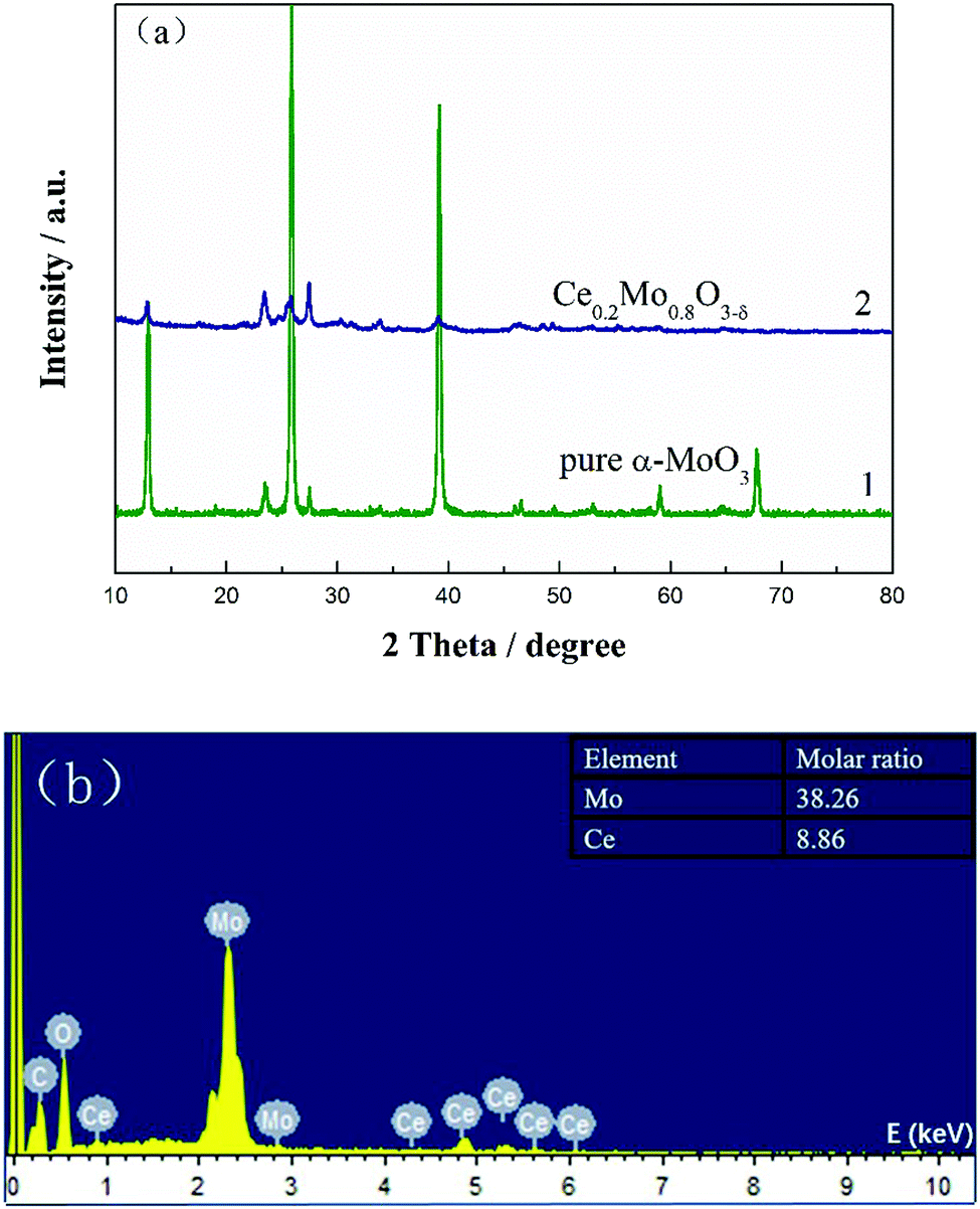 | ||
| Fig. 1 (a) XRD patterns of pure α-MoO3 nanorods and Ce0.2Mo0.8O3−δ; (b) EDX spectrum of Ce0.2Mo0.8O3−δ nanorods. The inset is the corresponding molar ratio of Mo to Ce. | ||
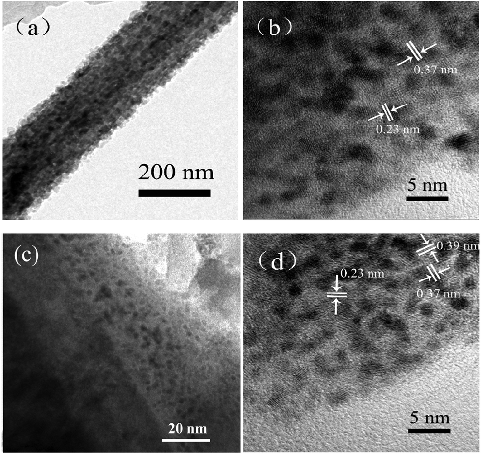
To acquire morphological information about the sample, SEM and TEM images were obtained. Fig. 2a and b are typical SEM images of the pure α-MoO3 nanorods. Fig. 2c is a typical TEM image of one single α-MoO3 nanorod. The SEM and TEM images show that the surface of the as-obtained α-MoO3 nanorods is very smooth and clean. The width of such α-MoO3 nanorods is about 250 nm. Fig. 2d displays the HRTEM image of a pure α-MoO3 nanorod. The lattice fringes of 0.37 nm and 0.40 nm correspond to the (001) and (100) planes of the α-MoO3 crystal. The HRTEM image indicates that α-MoO3 nanorods grow along the [001] orientation.
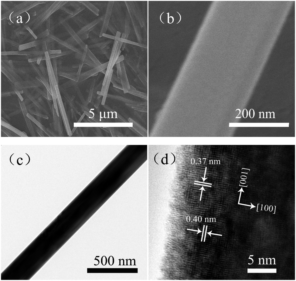 | ||
| Fig. 2 SEM images of (a) MoO3 nanorods and (b) one single MoO3 nanorod; (c) TEM image of one single MoO3 nanorod; (d) high-resolution TEM (HRTEM) image of the MoO3 nanorods. | ||
Furthermore, SEM images of the Ce0.2Mo0.8O3−δ nanorods are shown in Fig. 3a and b. Fig. 3c presents a typical TEM image of the Ce0.2Mo0.8O3−δ nanorods. Both the SEM and TEM observations clearly identified that the nanorod structure can be retained in the Ce-doped MoO3 (Ce0.2Mo0.8O3−δ), but also show a rougher surface relative to the individual MoO3 nanorods (Fig. 2). The width of the Ce0.2Mo0.8O3−δ nanorods is about 330 nm. The HRTEM image of the Ce0.2Mo0.8O3−δ nanorods is shown in Fig. 3d. The crystal lattice fringes of 0.35, 0.37 nm and 0.39 nm correspond to the (060), (001), and (100) planes of the α-MoO3 crystal, respectively. Notably, the value for the (100) plane is smaller than that for the pure α-MoO3 nanorods, and the lattice fringes are distorted and not distinct, which can be ascribed to lattice defects caused by the incorporation of Ce into the α-MoO3.
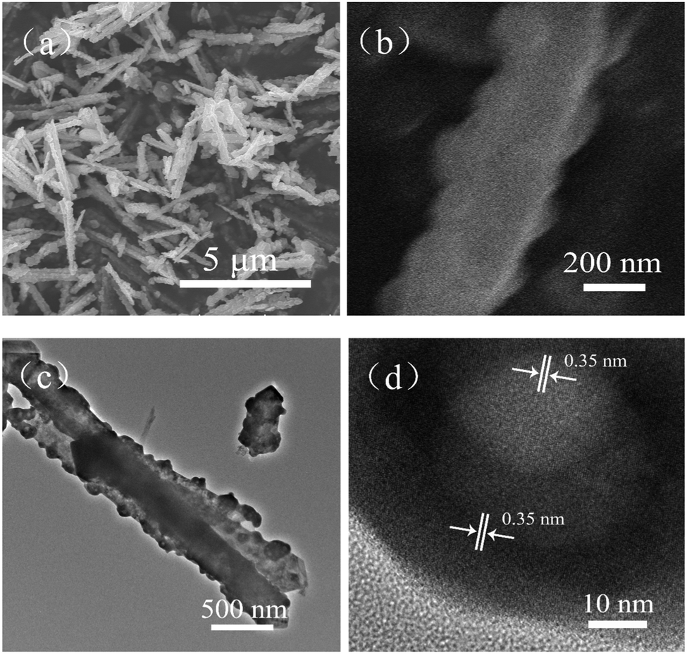 | ||
| Fig. 3 SEM images of (a) Ce0.2Mo0.8O3−δ nanorods and (b) one single Ce0.2Mo0.8O3−δ nanorod; (c) TEM image of one single Ce0.2Mo0.8O3−δ nanorod; (d) high-resolution TEM (HR-TEM) image of the Ce0.2Mo0.8O3−δ nanorods. | ||
Raman spectra were recorded to investigate the microstructure of the Ce-doped α-MoO3 nanorods. Fig. 4 compares the Raman spectra of α-MoO3 and the Ce-doped α-MoO3 nanorods. The spectra of both the non-doped and Ce-doped α-MoO3 nanorods show the main Raman bands (e.g., 128, 158, 246, 292, 337, 668, 819 and 994 cm−1) associated with α-MoO3.45 Obviously, there is a slightly negative shift of these bands for the Ce-doped α-MoO3 compared with the undoped α-MoO3, which proves the particle sizes of the Ce-doped α-MoO3 are smaller than the undoped α-MoO3, as doping of Ce into α-MoO3 inhibits crystallization.46 These results are also in accordance with the XRD patterns. Moreover, the intensities of the vibration modes vary with Ce doping, which indicates that while the introduction of Ce induces defects and oxygen vacancies, it does not cause differences during the structure formation.47 The intensity ratio (I819/I994) for the Ce-doped α-MoO3 is lower than that of the pure α-MoO3, indicating incorporation of Ce into the α-MoO3 lattice and more subsequent oxygen vacancies and enhanced defects. The results are also in accordance with the TEM images. As will be discussed further, this is beneficial for improving the co-catalytic ability of Ce0.2Mo0.8O3−δ solid solutions for methanol electrooxidation.
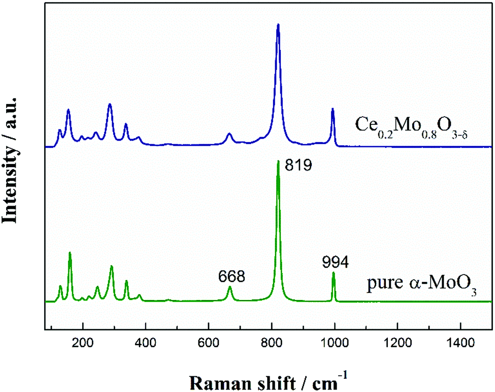 | ||
| Fig. 4 Raman spectra of pure α-MoO3 and the Ce0.2Mo0.8O3−δ nanorods. | ||
3.2 Pt/Ce0.2Mo0.8O3−δ catalysts
The XRD patterns of the Pt/Ce0.2Mo0.8O3−δ and Pt/MoO3 catalysts are shown in Fig. S1 (ESI†). In addition to the diffraction peaks of α-MoO3 and Ce0.2Mo0.8O3−δ which are also found in the patterns of the Pt/MoO3 and Pt/Ce0.2Mo0.8O3−δ catalysts, the major diffraction peaks located at 2θ values of about 39.6°, 46.3° and 67.3° were indexed to Pt(111), Pt(200) and Pt(220) diffraction peaks of a face centered cubic (fcc) structure, respectively. Apparently, the diffraction peaks for Pt/Ce0.2Mo0.8O3−δ are slightly broader than those of the undoped samples. The average crystallite sizes of the Pt nanoparticles in all the samples were estimated to be 2.0 and 2.2 nm for Pt/Ce0.2Mo0.8O3−δ and Pt/MoO3, respectively. The crystallite sizes of the Pt nanoparticles for Pt/Ce0.2Mo0.8O3−δ are smaller than those of Pt/MoO3, which suggests that the Ce0.2Mo0.8O3−δ with a larger specific surface area is conducive to dispersion of the Pt nanoparticles. There is no obvious variation in the positions of the Pt diffraction peaks between the two catalysts. However, the lattice constant for the Pt in Pt/Ce0.2Mo0.8O3−δ is 0.3912 nm, which is smaller than that for Pt/MoO3 (0.3920 nm). These results can be ascribed to the electronic interactions between Pt and the oxides as well as Ce and Mo.24Fig. 5 shows the TEM images of Pt/Ce0.2Mo0.8O3−δ and Pt/MoO3 at different magnifications. As seen in Fig. 5a and b, Pt particles in Pt/MoO3 are deposited on the support with a particle size of 2.2 nm. The lattice fringes of the Pt(111) and α-MoO3(001) facets can also be observed in Fig. 5b. It can be observed from Fig. 5c and d that the Pt particles are fairly well-dispersed on the support with similar particle sizes to those of Pt/MoO3. The direct observation of lattice fringes indicates the formation of a Ce0.2Mo0.8O3−δ solid solution and successful reduction of Pt, which is consistent with the results from XRD.
 | ||
| Fig. 5 (a) TEM and (b) HRTEM images of the Pt/MoO3 catalyst; (c) TEM and (d) HRTEM images of the Pt/Ce0.2Mo0.8O3−δ. | ||
To further investigate the surface states of the catalysts, Pt/Ce0.2Mo0.8O3−δ, Pt/MoO3 and commercial Pt/C catalysts were analyzed using XPS. As shown in Fig. 6a–c, the deconvoluted spectra for the Pt 4f peaks of the three catalysts were compared. All the Pt 4f signals consist of three doublets, which can be attributed to different valence states of Pt (for detailed results, see the ESI,† Table S1).48 It was noted that the binding energy of the Pt 4f peaks for Pt/Ce0.2Mo0.8O3−δ and Pt/MoO3 shifted positively compared to Pt/C, which can be attributed to the interactions between Pt and the oxides.49–51 Obviously, the binding energy peak of Pt0 is the dominant component of the Pt 4f. Moreover, the Pt0 content of Pt/Ce0.2Mo0.8O3−δ was increased by 4.0% and 10.9% compared to the Pt/MoO3 and commercial Pt/C catalysts, respectively, supplying more available active Pt sites for methanol adsorption.
 | ||
| Fig. 6 XPS spectra of Pt 4f for the (a) Pt/Ce0.2Mo0.8O3−δ, (b) Pt/MoO3 and (c) commercial Pt/C catalysts. XPS spectra of (d) Ce 3d for Pt/Ce0.2Mo0.8O3−δ, and (e) Mo 3d for Pt/Ce0.2Mo0.8O3−δ and Pt/MoO3. (f) XPS spectra of O 1s for Pt/Ce0.2Mo0.8O3−δ and Pt/MoO3. | ||
XPS spectra of the Ce 3d and Mo 3d peaks were also obtained to explore charge transfer from the support. As shown in Fig. 6d, the XPS spectra of Ce 3d show binding energies at 882.1 and 990.4 eV, and 886.1 and 904.4 eV that correspond to the Ce 3d5/2 and Ce 3d3/2 signals of Ce(IV) and Ce(III), respectively.39,48,52 The large amount of noise in the Ce 3d spectrum of the Pt/Ce0.2Mo0.8O3−δ catalyst makes it difficult to obtain a refined XPS spectrum for Ce, which may be due to the low amount of Ce in the Pt/Ce0.2Mo0.8O3−δ catalyst. Fig. 6e exhibits the Mo 3d XPS spectra of Pt/Ce0.2Mo0.8O3−δ and Pt/MoO3. The Mo 3d5/2 and 3d3/2 peaks located at 233.0 and 236.1 eV, and 232.8 and 235.9 eV correspond to Mo(VI).53 This shows that Mo is mainly present on the catalyst surface in the form of MoO3. The binding energies of the Mo 3d peaks for Pt/Ce0.2Mo0.8O3−δ are increased by 0.2 eV compared to Pt/MoO3 (Table S2, ESI†). In addition to the characteristic peaks of Mo(VI) ions and the two Mo 3d XPS peaks, the weaker peaks at 231.5 and 234.6 eV correspond to Mo(V) ions. This confirms the existence of suboxides in MoO3 due to the presence of Mo(V). Consequently, the molecular formula of the MoO3 should be precisely defined as MoO3−δ, where δ represents the number of oxygen vacancies.45 Notably, the content of Mo(V) ions in the Ce-doped MoO3 is higher than that in the pure MoO3, which indicates that the Ce-doped MoO3 possesses more oxygen vacancies. This can be attributed to the doping of Ce resulting in the formation of lattice defects in MoO3, which facilitates the generation of oxygen vacancies.36 Moreover, the existence of Ce(IV) and Ce(III) breaks the intrinsic charge balance. Thus, oxygen vacancies can occur as a result of charge-transfer reactions. These results further prove that Ce ions have been incorporated into the MoO3 lattice. From the above results, it can be concluded that doping with Ce increases the oxygen vacancies and defects, which is also consistent with the Raman and TEM analysis. This result was also verified using O 1s spectra of Pt/Ce0.2Mo0.8O3−δ and Pt/MoO3, as shown in Fig. 6f. Based on analysis of the Gaussian resolution, the peaks located at 530.7, 531.5, and 532.8 eV were assigned to lattice oxygen,54 oxygen vacancies,55 and chemisorbed oxygen or hydroxyl groups of MoO3,56 respectively. It is obvious that Ce0.2Mo0.8O3−δ possesses more oxygen vacancies and chemically absorbed oxygen sites. These results indicate that Ce doping can increase the number of oxygen vacancies and hydroxyl groups available for reaction.
3.3 Electrochemical measurements
Firstly, the correlation between the Ce doping level and the electrochemical performance towards methanol oxidation was studied, as shown in Fig. S2 (ESI†). Three different Ce doping amounts were studied for the Ce-doped MoO3 support in terms of their resulting mass activity of Pt during the methanol oxidation. The peak current density values for methanol electrooxidation were determined to be 546, 585, and 568 mA mg Pt−1 for the Pt/Ce0.16Mo0.84O3−δ, Pt/Ce0.20Mo0.80O3−δ and Pt/Ce0.25Mo0.75O3−δ samples, respectively. Among them, the peak current density of Pt/Ce0.20Mo0.80O3−δ is the largest, showing the highest activity. Furthermore, the ratio of the forward oxidation current density to the backward current density (If/Ib) for the Pt/Ce0.20Mo0.80O3−δ catalyst is 0.91, which is higher than those of the Pt/Ce0.16Mo0.84O3−δ (0.88) and Pt/Ce0.25Mo0.75O3−δ (0.78). This suggests that the methanol electrooxidation activity of a Pt catalyst supported on Ce-doped MoO3 is greatly dependent on the ratio of Ce:Mo. The optimal Ce:Mo ratio was determined to be 0.20:0.80, which is capable of generating the highest methanol electrooxidation activity and COad tolerance.
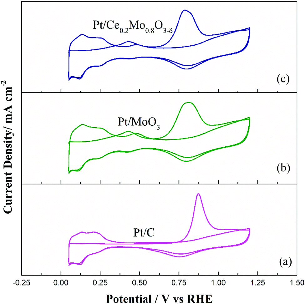
Fig. 7 compares the cyclic voltammetry behavior of the Pt/Ce0.2Mo0.8O3−δ, Pt/MoO3 and commercial Pt/C catalysts in 0.5 mol L−1 H2SO4 solution. The cyclic voltammetry curve of commercial Pt/C shows typical behavior of Pt in an acid solution. It is noteworthy that a new couple of sensitive redox peaks was obtained for the Pt/Ce0.2Mo0.8O3−δ and Pt/MoO3 catalysts between 400 and 500 mV. These redox peaks are attributed to MoO2/MoO3.57,58 It is obvious that the Mo phase exists in an electrochemically active form. This result can be further verified through CO stripping tests. The electrochemical surface area (ECSA) was estimated from the hydrogen adsorption/desorption regions, assuming that the coulombic charge of a monolayer of adsorbed H on Pt is 0.21 mC cm−2.59 The ECSAs of the Pt/Ce0.2Mo0.8O3−δ, Pt/MoO3 and commercial Pt/C are about 53.8, 49.7 and 46.8 m2 g−1, respectively. Apparently, the ECSA of Pt/Ce0.2Mo0.8O3−δ is higher than that of the Pt/C catalyst, which seems to be because the crystallite sizes of the Pt nanoparticles in Pt/Ce0.2Mo0.8O3−δ and Pt/MoO3 are smaller than those of the Pt/C catalyst.
 | ||
| Fig. 7 CV curves of the commercial Pt/C, Pt/MoO3 and Pt/Ce0.2Mo0.8O3−δ catalysts in 0.5 mol L−1 H2SO4 solution at a scan rate of 20 mV s−1 at 25 °C. | ||
CO stripping voltammetry tests were carried out to further explore the CO tolerance of the Pt catalysts, as shown in Fig. 8. As demonstrated in Fig. 8a, the Pt/C catalyst shows a single CO stripping peak at 869 mV. Compared to Pt/C, the Mo-containing catalysts showed different characteristic CO stripping peaks. From Fig. 8b and c, the CO stripping peaks for Pt/MoO3 and Pt/Ce0.2Mo0.8O3−δ were wider, with poor resolution, compared to the Pt/C catalyst. It is noteworthy that Pt/Ce0.2Mo0.8O3−δ presents two different oxidation peaks in addition to the main CO oxidation peak. The anodic peaks at 0.40 V in the first positive cycling scan were attributed to adsorbed CO (COad) and Mo oxidation peaks. The peaks at 0.45 V in the second positive cycling scan were attributed to the redox process of Mo.60 These results are in good agreement with the CV curves of the catalysts in 0.5 mol L−1 H2SO4 solution. Apparently, the oxidation peak potential of Pt/Ce0.2Mo0.8O3−δ is close to that of Pt/MoO3, and markedly lower than that of Pt/C (Table S3, ESI†). Furthermore, the onset peak potential of Pt/Ce0.2Mo0.8O3−δ is lower than that of the other two catalysts. These results show that Pt/Ce0.2Mo0.8O3−δ is more active than Pt/MoO3 and Pt/C in oxidation of CO, which may due to the increased presence of OH species caused by Ce doping, which is in agreement with the XPS results.
 | ||
| Fig. 8 CO stripping voltammograms for the (a) commercial Pt/C, (b) Pt/MoO3 and (c) Pt/Ce0.2Mo0.8O3−δ catalysts. | ||
CV curves of the Pt/Ce0.2Mo0.8O3−δ, Pt/MoO3 and commercial Pt/C catalysts for the methanol oxidation reaction (MOR) were obtained in 0.5 mol L−1 H2SO4 or 0.5 mol L−1 H2SO4 with 0.5 mol L−1 CH3OH. For comparison, the currents of the MOR were normalized to the mass of Pt on the electrode surface for each catalyst. For simple observation, the currents of the MOR were also normalized to the electrochemical active surface area of the Pt on the electrode surface for each catalyst (the inset in Fig. 9). The actual mass of Pt was determined from the ICP tests. The mass of Pt in the Pt/Ce0.2Mo0.8O3−δ and Pt/MoO3 catalysts was 19.6 wt% and 19.2 wt%, respectively, and the measured results are close to the nominal value. The CV results are shown in Fig. 9a and are summarized in Table S3 (ESI†). The onset potentials of the Pt/Ce0.2Mo0.8O3−δ, Pt/MoO3 and Pt/C catalysts were 403, 478, and 510 mV, respectively. The lower value of the Pt/Ce0.2Mo0.8O3−δ catalyst clearly indicates that methanol molecules are more easily oxidized with this catalyst compared to the other two catalysts. Furthermore, the mass activity of Pt/Ce0.2Mo0.8O3−δ was up to 585 mA mg Pt−1, which is about 1.3 times higher than that of Pt/MoO3 and 1.6 times higher than that of the Pt/C catalyst. Corresponding results are also shown in the inset of Fig. 9. Furthermore, the ratio of the forward oxidation current density to the backward current density (If/Ib) for the Pt/Ce0.2Mo0.8O3−δ catalyst is 0.91, which is higher than those of the Pt/MoO3 catalyst (0.77) and the commercial Pt/C catalyst (0.72). The higher ratio reveals that the Pt/Ce0.2Mo0.8O3−δ catalyst is more effective at removal of poisoning species such as CO on the catalyst surface, which leads to a better tolerance.60 The enhanced activity can be attributed to synergistic effects between the Pt and Ce0.2Mo0.8O3−δ, i.e. the large number of OHads species attached to the surface of Ce0.2Mo0.8O3−δ is conducive to the oxidation of poisonous COads, which has already been verified from the CO stripping voltammetry curves. According to the literature,57,61–63 one possible reaction mechanism for methanol oxidation using Pt/MoO3 is a bifunctional mechanism. The reaction can be represented as follows:
| MoO3 + H2O → MoO3–OHad + e− | (1) |
| Pt–COads + MoO3–OHads → CO2 + H+ + Pt + MoO3 + e− | (2) |
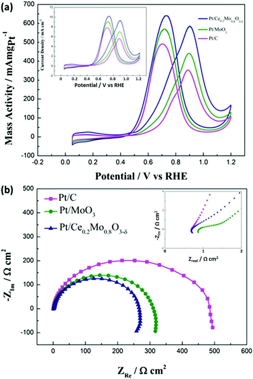 | ||
| Fig. 9 (a) CV plots for methanol oxidation on Pt catalysts deposited on traditional carbon, MoO3 and Ce0.2Mo0.8O3−δ supports. Electrolyte: 0.5 mol L−1 H2SO4 + 0.5 mol L−1 CH3OH. The inset results were normalized using the electrochemical active surface areas of Pt. (b) Electrochemical impedance spectra of the Pt/Ce0.2Mo0.8O3−δ, Pt/MoO3 and commercial Pt/C catalysts in 0.5 mol L−1 H2SO4 + 0.5 mol L−1 CH3OH at 25 °C. The inset shows an amplified part of the high frequency region. | ||
The presence of MoO3 groups may induce OHads species to react with COads on the Pt surface to produce CO2. Consequently, more active sites on the Pt surface are released, thereby facilitating methanol electrooxidation.64 In this work, the 1D nanostructure provides a large surface area for the dispersion of Pt nanoparticles, increasing the interactions between the Pt and Ce0.2Mo0.8O3−δ. Also, Ce0.2Mo0.8O3−δ is able to release more oxygen vacancies compared with un-doped MoO3, due to the lattice defects caused by incorporation of Ce into the MoO3 lattice. The increased number of oxygen vacancies in Ce0.2Mo0.8O3−δ leads to a higher amount of adsorbed OHads species, which is conducive to CO oxidation. In this context, Pt/Ce0.2Mo0.8O3−δ catalysts will exhibit the best performance for methanol electrooxidation because of the 1D nanostructure and a higher number of oxygen vacancies on Ce0.2Mo0.8O3−δ.
CA curves (Fig. S3, ESI†) of the Pt/Ce0.2Mo0.8O3−δ, Pt/MoO3 and commercial Pt/C catalysts were obtained to further investigate the methanol electrooxidation activity and stability. There is a sharp drop in the oxidation current for all three catalysts due to the formation of poisonous species and intermediates in the methanol electrooxidation.65 After 1000 s, the current gradually decays for all the catalysts, but Pt/Ce0.2Mo0.8O3−δ exhibits a higher current density and less current decay compared to the Pt/MoO3 and commercial Pt/C catalysts. It is obvious that Pt/Ce0.2Mo0.8O3−δ exhibits a higher electrocatalytic activity and stability for methanol electrooxidation than the other two catalysts.
The long-term stability of the Pt catalysts was further investigated by performing continuous potential cycling in 0.5 mol L−1 H2SO4 with 0.5 mol L−1 CH3OH over 1000 cycles (Fig. S4, ESI†). The mass activity retention for Pt/MoO3 was 71.2%, which is slightly higher than that of the Pt/C catalyst (67.6%). Moreover, Pt/Ce0.2Mo0.8O3−δ showed the highest stability (80.0%) during the oxidation of methanol, which could be attributed to the strong interactions between Pt and Ce0.2Mo0.8O3−δ.
CO stripping and chronoamperometry (CA) experiments were also carried out after accelerated aging tests as a quantitative method of determining the methanol oxidation using these studied Pt catalysts. As shown in Fig. S5 (ESI†), the corresponding CO stripping comparison indicated that the oxidation peak potential of CO with the Pt/Ce0.2Mo0.8O3−δ was still lower than that of Pt/MoO3 and Pt/C. Moreover, the onset potentials for CO oxidation on Pt/Ce0.2Mo0.8O3−δ, Pt/MoO3, and Pt/C were determined as 0.526, 0.587 and 0.742 V, respectively. They are close to the results obtained before the accelerated stress tests (ASTs) and the Pt/Ce0.2Mo0.8O3−δ catalyst still showed the lowest onset potential. Therefore, Pt/Ce0.2Mo0.8O3−δ is still more active than Pt/MoO3 and Pt/C, with enhanced Coad tolerance, during oxidation of methanol after the accelerated aging tests.
CA curves of methanol oxidation on the Pt/Ce0.2Mo0.8O3−δ, Pt/MoO3, and commercial Pt/C catalysts were obtained to further evaluate the methanol electrooxidation activity and stability after the ASTs. As shown in Fig. S6 (ESI†), the current gradually decays for all these catalysts. It is worth noting that the current decay values for the Pt/Ce0.2Mo0.8O3−δ (4%), Pt/MoO3 (17%), and Pt/C (26%) catalysts are larger compared to the corresponding result before the ASTs. Also, compared to the others, the Pt/C catalyst exhibited a larger decay. Therefore, Pt/Ce0.2Mo0.8O3−δ still exhibits a higher electrocatalytic activity and stability for methanol electrooxidation than the other two studied Pt catalysts after the ASTs.
In Fig. S7 (ESI†), the curves of (a) and (b) represent the results before and after the ASTs for Pt/Ce0.2Mo0.8O3−δ and Pt/MoO3. It is obvious that the ECSAs of the Pt in the two catalysts are slightly reduced, according to the smaller H adsorption/desorption peaks in the CVs. This could be due to migration and agglomeration of the Pt nanoparticles during the cycling, which was also observed with traditional carbon-supported Pt catalysts. More importantly, the redox peaks around 0.4–0.5 V associated with molybdenum oxides appear smaller relative to the results before the ASTs, which suggests that the active areas for the molybdenum oxides of the two catalysts are reduced. Therefore, the Ce0.2Mo0.8O3−δ and MoO3 oxides are slightly dissolved in the acidic medium during the ASTs. However, the dissolution of the metal oxides has little effect on the overall performance of the Pt catalysts.
The charge transfer resistance was determined using EIS to reflect methanol electrooxidation activity. It should be noted that EIS experiments in this work were carried out at 0.6 V vs. RHE, during which the degree of methanol oxidation was determined from the dehydrogenation reaction of the methanol. We have systematically studied methanol oxidation at different potentials to elucidate the reaction mechanism.66 The chosen potential is within the range of the electrochemical activation ranges, rather than the intermediate migration control ranges. Thus, it can be used to more appropriately study the catalytic activity of the catalyst for methanol oxidation. In Nyquist plots, the smaller the diameter of the semicircle is, the better the electrocatalytic activity is. It is well known that the diameter of the semicircle is strongly linked to the charge reaction resistance (Rct) for methanol electrooxidation.66 It can be seen from Fig. 9b that the semicircle for the Pt/Ce0.2Mo0.8O3−δ catalyst is smaller than those of the Pt/MoO3 and commercial Pt/C catalysts, indicating that the electrooxidation rate for Pt/Ce0.2Mo0.8O3−δ is much faster than those of the other two catalysts, which is in accordance with the CV and CA results. This result can be ascribed to the intermediate COads from methanol dehydrogenation being effectively oxidized on the Pt/Ce0.2Mo0.8O3−δ catalyst. As a result, the methanol electrooxidation rate can be improved by addition of MoO3 and further promoted by doping with Ce. The faster electrooxidation rate is indicative of the improved methanol electrooxidation activity of the catalyst. The intercept of the semicircle at the real axis in the high frequency (the inset in Fig. 9b) represents the electrolyte resistance (Rs) and the internal electrode resistance.67 Here we assume that the electrolyte resistance for all of the electrodes is the same. The difference in the internal electrode resistance could be used to compare the electrical conductivity of the catalysts, especially that associated with the oxide support. The internal resistance of the Pt/Ce0.2Mo0.8O3−δ catalyst is close to that of the Pt/C catalyst. However, the internal resistance of the Pt/Ce0.2Mo0.8O3−δ catalyst is lower than that of the Pt/MoO3 catalyst, which is due to the improvement in the electrical conductivity of MoO3 caused by doping with Ce. The higher electrical conductivity has also certainly improved the electrocatalytic activity of the catalyst for methanol electrooxidation.
Finally, it should be noted that the onset potential for methanol oxidation reflects the overpotential necessary to realize de-hydrogenation and removal of the intermediates (e.g., COad) to complete the oxidation process for methanol molecules. Thus, this is the possible reason why the overall onset potential for methanol oxidation is nearly independent of the type of support for various Pt catalysts. Methanol oxidation is complicated by the formation of COads poisoning intermediates or even other oxygen-containing species such as formaldehyde and formic acid. The ratio of the forward anodic peak current (If) to the backward anodic peak current (Ib) is usually used as a metric for evaluating the tolerance of Pt catalysts towards the accumulation of poisoning carbonaceous species. We have analyzed the relevant results for the different catalysts based on this. The ratio of If/Ib for the Pt/Ce0.2Mo0.8O3−δ catalyst is 0.91, which is higher than those of the Pt/MoO3 catalyst (0.77), and the commercial Pt/C catalyst (0.72). The higher ratio reveals that the Pt/Ce0.2Mo0.8O3−δ catalyst is more effective at removal of poisoning species such as CO on the Pt catalyst surface, which leads to a better tolerance. The onset potential of the CO tripping test directly reflects the difficulty level of CO oxidation, which would affect the onset potential for methanol oxidation.68 However, it should be noted that discrepancies in the onset potential between the overall methanol oxidation and CO oxidation can be explained by the similar activation energy for the most critical de-hydrogenation step found with various Pt catalysts. Our previous methanol oxidation research using EIS also suggested that de-hydrogenation in a low overpotential region is the rate determining step.66 Thus, unlike CO oxidation, the overall onset potential remains nearly the same for all of the studied Pt catalysts on various supports. This also suggests that the supports play a more important role in facilitating CO oxidation relative to the de-hydrogenation process. A more detailed understanding still remains elusive.
4. Conclusions
In summary, a facile two-step hydrothermal method was developed to prepare a novel Ce-doped MoO3 (e.g., Ce0.2Mo0.8O3−δ) nanorod support for electrocatalysis applications. Doping MoO3 with Ce ions was beneficial for changing the surface element composition and promoting the active oxygen content at the MoO3 surface. The Ce0.2Mo0.8O3−δ nanorods were successfully used as a support to uniformly disperse Pt nanoparticles (2–3 nm). The Pt/Ce0.2Mo0.8O3−δ catalyst was studied for use in methanol electrooxidation, and exhibited an enhanced electrochemical performance, especially in terms of the COads tolerance, when compared with non-doped MoO3-supported Pt (Pt/MoO3) and commercial Pt/C catalysts. Especially, the oxide support is also able to provide an increased mass activity of Pt for the methanol oxidation. The mass activity of the Pt/Ce0.2Mo0.8O3−δ catalyst for methanol oxidation (585 mA mg Pt−1) was calculated to be 1.3 and 1.6 times higher than that of the Pt/MoO3 (442 mA mg Pt−1) and commercial Pt/C (20 wt%) (353 mA mg Pt−1) catalyst, respectively. The rough surface of the mixed oxide provides more anchor sites for Pt nucleation and yields well-dispersed Pt nanoparticles with an even smaller size (2–3 nm) compared to commercial Pt/C (3–4 nm). The improvements can be attributed to strengthened metal–support interactions, which are derived from the doping with Ce, and subsequently from refining of the electronic structure of MoO3 and an increase of the surface oxygen vacancies and hydroxyl groups. This is also beneficial for removing CO-like intermediate products on the Pt surface, thereby more Pt active sites are released during the methanol oxidation. In addition, this work has demonstrated that the 1D nanostructured oxide support is an effective non-carbon support for electrocatalysis using a Pt catalyst. The unique structural and synergistic effects for electrocatalysis observed with the Ce-doped MoO3 nanorod support could be extended to other important electrochemical reactions such as oxygen and hydrogen reactions as well as photocatalysis for energy and environmental applications.Acknowledgements
C. L. acknowledges support from the Nature Science Foundation of the Heilongjiang Province of China (Grant No. B201203), and the Foundation of Innovative and Entrepreneur Training Plan for College Students of the Heilongjiang Province of China (No. 201510212971). G. W. is thankful for financial support from the New York State Center of Excellence in Materials Informatics and startup funds from the University at Buffalo, along with the U.S. Department of Energy, Fuel Cell Technologies Office.References
- H. Huang and X. Wang, J. Mater. Chem. A, 2014, 2, 6266–6291 Search PubMed.
- C. Pan, Y. Li, Y. Ma, X. Zhao and Q. Zhang, J. Power Sources, 2011, 196, 6228–6231 Search PubMed.
- E. Antolini and E. R. Gonzalez, J. Power Sources, 2010, 195, 3431–3450 Search PubMed.
- Y. Paik, S. S. Kim and O. H. Han, Angew. Chem., 2008, 47, 94–96 Search PubMed.
- Q. Li, T. Wang, D. Havas, H. Zhang, P. Xu, J. Han, J. Cho and G. Wu, Adv. Sci., 2016, 1600140, DOI:10.1002/advs.201600140.
- G. Wu, D. Li, C. Dai, D. Wang and N. Li, Langmuir, 2008, 24, 3566–3575 Search PubMed.
- H. Liu, C. Song, L. Zhang, J. Zhang, H. Wang and D. P. Wilkinson, J. Power Sources, 2006, 155, 95–110 Search PubMed.
- S. Zhou, T. Schultz, M. Peglowa and K. Sundmacherab, Phys. Chem. Chem. Phys., 2001, 3, 347–355 Search PubMed.
- J. Zhao, X. He, J. Tian, C. Wan and C. Jiang, Energy Convers. Manage., 2007, 48, 450–453 Search PubMed.
- S. K. Meher and G. R. Rao, ACS Catal., 2012, 2, 2795–2809 Search PubMed.
- P. Xiao, H. Song, X. Qiu, W. Zhu, L. Chen, U. Stimming and P. Bele, Appl. Catal., B, 2010, 97, 204–212 Search PubMed.
- A. Chen and P. Holt-Hindle, Chem. Rev., 2010, 110, 3767–3804 Search PubMed.
- G. Wu, R. Swaidan and G. Cui, J. Power Sources, 2007, 172, 180–188 Search PubMed.
- L. Li, G. Wu and B.-Q. Xu, Carbon, 2006, 44, 2973–2983 Search PubMed.
- J. Wang, G. Yin, Y. Shao, S. Zhang, Z. Wang and Y. Gao, J. Power Sources, 2007, 171, 331–339 Search PubMed.
- Y. Shao, G. Yin, Y. Gao and P. Shi, J. Electrochem. Soc., 2006, 153, A1093 Search PubMed.
- G. Wu, Y.-S. Chen and B.-Q. Xu, Electrochem. Commun., 2005, 7, 1237–1243 Search PubMed.
- G. Cui, P. K. Shen, H. Meng, J. Zhao and G. Wu, J. Power Sources, 2011, 196, 6125–6130 Search PubMed.
- H. Osgood, S. V. Devaguptapu, H. Xu, J. P. Cho and G. Wu, Nano Today, 2016, 11, 601–625 Search PubMed.
- T. Ioroi, T. Akita, S.-I. Yamazaki, Z. Siroma, N. Fujiwara and K. Yasuda, Electrochim. Acta, 2006, 52, 491–498 Search PubMed.
- Y. Li, C. Liu, Y. Liu, B. Feng, L. Li, H. Pan, W. Kellogg, D. Higgins and G. Wu, J. Power Sources, 2015, 286, 354–361 Search PubMed.
- S.-H. Lee, Y.-H. Kim, R. Deshpande, P. A. Parilla, E. Whitney, D. T. Gillaspie, K. M. Jones, A. H. Mahan, S. Zhang and A. C. Dillon, Adv. Mater., 2008, 20, 3627–3632 Search PubMed.
- S. Hu and X. Wang, J. Am. Chem. Soc., 2008, 130, 8126–8127 Search PubMed.
- L. Ma, X. Zhao, F. Si, C. Liu, J. Liao, L. Liang and W. Xing, Electrochim. Acta, 2010, 55, 9105–9112 Search PubMed.
- J.-K. Shin, S. M. Jeong, Y. Tak and S.-H. Baeck, Res. Chem. Intermed., 2010, 36, 715–724 Search PubMed.
- Q. Wang, D.-A. Zhang, Q. Wang, J. Sun, L.-L. Xing and X.-Y. Xue, Electrochim. Acta, 2014, 146, 411–418 Search PubMed.
- Polina A. Zosimova, A. V. Smirnov, S. N. Nesterenko, V. V. Yuschenko, W. Sinkler, J. Kocal, J. Holmgren and I. I. Ivanova, J. Phys. Chem. C, 2007, 111, 14790–14798 Search PubMed.
- Y. Wang, E. R. Fachini, G. Cruz, Y. Zhu, Y. Ishikawa, J. A. Colucci and C. R. Cabrera, J. Electrochem. Soc., 2001, 148, C222–C226 CrossRef CAS.
- R. S. Devan, R. A. Patil, J.-H. Lin and Y.-R. Ma, Adv. Funct. Mater., 2012, 22, 3326–3370 CrossRef CAS.
- L. Fang, Y. Shu, A. Wang and T. Zhang, J. Phys. Chem. C, 2007, 111, 2401–2408 Search PubMed.
- Y. Dong, S. Li, H. Xu, M. Yan, X. Xu, X. Tian, Q. Liu and L. Mai, Phys. Chem. Chem. Phys., 2013, 15, 17165–17170 Search PubMed.
- L. Mai, F. Yang, Y. Zhao, X. Xu, L. Xu, B. Hu, Y. Luo and H. Liu, Mater. Today, 2011, 14, 346–353 Search PubMed.
- R. Nadimicherla, Y. Liu, K. Chen and W. Chen, Solid State Sci., 2014, 34, 43–48 Search PubMed.
- D. Chen, M. Liu, L. Yin, T. Li, Z. Yang, X. Li, B. Fan, H. Wang, R. Zhang, Z. Li, H. Xu, H. Lu, D. Yang, J. Sun and L. Gao, J. Mater. Chem., 2011, 21, 9332 Search PubMed.
- P. Ren, X. Liu, K. Zhang, P. Zhang, F. Teng, Z. Zhang, E. Xie and P. Yan, Mater. Lett., 2014, 122, 320–322 Search PubMed.
- N. Illyaskutty, S. Sreedhar, H. Kohler, R. Philip, V. Rajan and V. P. M. Pillai, J. Phys. Chem. C, 2013, 117, 7818–7829 Search PubMed.
- Q.-Y. Ouyang, L. Li, Q.-S. Wang, Y. Zhang, T.-S. Wang, F.-N. Meng, Y.-J. Chen and P. Gao, Sens. Actuators, B, 2012, 169, 17–25 Search PubMed.
- Y. Y. Chu, Z. B. Wang, Z. Z. Jiang, D. M. Gu and G. P. Yin, Adv. Mater., 2011, 23, 3100–3104 Search PubMed.
- M. A. Scibioh, S.-K. Kim, E. A. Cho, T.-H. Lim, S.-A. Hong and H. Y. Ha, Appl. Catal., B, 2008, 84, 773–782 Search PubMed.
- K. Yang, Z. Deng and J. Suo, J. Power Sources, 2012, 201, 274–279 Search PubMed.
- M.-M. Titirici, M. Antonietti and A. Thomas, Chem. Mater., 2006, 18, 3808–3812 Search PubMed.
- Q. Wang, J. Sun, Q. Wang, D.-A. Zhang, L. Xing and X. Xue, J. Mater. Chem. A, 2015, 3, 5083–5091 Search PubMed.
- C. Wang, Z. Chen, Y. He, L. Li and D. Zhang, Appl. Surf. Sci., 2009, 255, 6881–6887 Search PubMed.
- V. Štengl, S. Bakardjieva and N. Murafa, Mater. Chem. Phys., 2009, 114, 217–226 Search PubMed.
- M. Dieterle, G. Weinberg and G. Mestl, Phys. Chem. Chem. Phys., 2002, 4, 812–821 Search PubMed.
- B. Gao, H. Fan and X. Zhang, J. Phys. Chem. Solids, 2012, 73, 423–429 Search PubMed.
- S. Bai, C. Chen, D. Zhang, R. Luo, D. Li, A. Chen and C.-C. Liu, Sens. Actuators, B, 2014, 204, 754–762 Search PubMed.
- F. ç. Larachi, J. Pierre, A. Adnot and A. Bernis, Appl. Surf. Sci., 2002, 195, 236–250 Search PubMed.
- D. Higgins, M. A. Hoque, M. H. Seo, R. Wang, F. Hassan, J.-Y. Choi, M. Pritzker, A. Yu, J. Zhang and Z. Chen, Adv. Funct. Mater., 2014, 24, 4325–4336 Search PubMed.
- G. Wu, R. Swaidan, D. Li and N. Li, Electrochim. Acta, 2008, 53, 7622–7629 Search PubMed.
- J. Xi, J. Wang, L. Yu, X. Qiu and L. Chen, Chem. Commun., 2007, 1656–1658, 10.1039/b618310g.
- M. Chen, X. Wang, Y. Yu, Z. Pei, X. Bai, C. Sun, R. Huang and L. Wen, Appl. Surf. Sci., 2000, 158, 134–140 Search PubMed.
- N. P. Lebedeva and G. J. M. Janssen, Electrochim. Acta, 2005, 51, 29–40 Search PubMed.
- S. Bai, S. Chen, L. Chen, K. Zhang, R. Luo, D. Li and C. C. Liu, Sens. Actuators, B, 2012, 174, 51–58 Search PubMed.
- Y. Peng, S. Qin, W.-S. Wang and A.-W. Xu, CrystEngComm, 2013, 15, 6518 Search PubMed.
- Y. Mao, W. Li, X. Sun, Y. Ma, J. Xia, Y. Zhao, X. Lu, J. Gan, Z. Liu, J. Chen, P. Liu and Y. Tong, CrystEngComm, 2012, 14, 1419–1424 Search PubMed.
- E. I. Santiago, G. A. Camara and E. A. Ticianelli, Electrochim. Acta, 2003, 48, 3527–3534 Search PubMed.
- W. Li, L. P. Tian, Q. Huang, H. Li, H. Chen and X. Lian, J. Power Sources, 2002, 104, 281–288 Search PubMed.
- T. Ioroi, N. Fujiwara, Z. Siroma, K. Yasuda and Y. Miyazaki, Electrochem. Commun., 2002, 4, 442–446 Search PubMed.
- T. Ioroi, K. Yasuda, Z. Siroma, N. Fujiwara and Y. Miyazaki, J. Electrochem. Soc., 2003, 150, A1225 Search PubMed.
- S. Mukerjee, R. C. Urian, S. J. Lee, E. A. Ticianelli and J. McBreen, J. Electrochem. Soc., 2004, 151, A1094 Search PubMed.
- Y. Wang, R. Fachini, A. Cruz, Y. Zhu, Y. Ishikawa, J. A. Colucci and C. R. Cabrera, J. Electrochem. Soc., 2001, 148, C222–C226 Search PubMed.
- Z. Jusys, T. J. Schmidt, L. Dubau, K. Lasch, L. Jorissen, J. Garche and R. J. Bhem, J. Power Sources, 2002, 105, 297–304 Search PubMed.
- Z. Sun, X. Wang, Z. Liu, H. Zhang, P. Yu and L. Mao, Langmuir, 2010, 26, 12383–12389 Search PubMed.
- Z.-P. Sun, X.-G. Zhang, Y.-Y. Liang, H. Tong, R. L. Xue, S. D. Yang and H.-L. Li, J. Electroanal. Chem., 2009, 633, 1–6 Search PubMed.
- G. Wu, L. Li and B.-Q. Xu, Electrochim. Acta, 2004, 50, 1–10 Search PubMed.
- D.-M. Gu, Y.-Y. Chu, Z.-B. Wang, Z.-Z. Jiang, G.-P. Yin and Y. Liu, Appl. Catal., B, 2011, 102, 9–18 Search PubMed.
- O. Guillén-Villafuerte, G. García, R. Guil-López, E. Nieto, J. Rodríguez, J. Fierro and E. Pastor, J. Power Sources, 2013, 231, 163–172 Search PubMed.
Footnote |
| † Electronic supplementary information (ESI) available. See DOI: 10.1039/c6cp07005a |
| This journal is © the Owner Societies 2017 |