 Open Access Article
Creative Commons Attribution 3.0 Unported Licence
Enlargement of the organic solid-state DFB laser wavelength tuning range by the use of two complementary luminescent dyes doped into the host matrix†
Kacper
Parafiniuk
 *,
Lech
Sznitko
,
Dominika
Wawrzynczyk
 ,
Andrzej
Miniewicz
 and
Jaroslaw
Mysliwiec
Advanced Materials Engineering and Modelling Group, Faculty of Chemistry, Wroclaw University of Science and Technology, Wybrzeze Wyspianskiego 27, 50-370 Wroclaw, Poland. E-mail: kacper.parafiniuk@pwr.edu.pl
First published on 22nd June 2017
Abstract
The spectral tuning range of dye lasers is closely associated with the gain profile provided by the utilized luminescent compound. Here, we present the results of studies aimed at broadening the wavelength tuning range in distributed feedback (DFB) lasers, made up of polymeric layers doped with a mixture of two complementary dyes. We have used the 3-(2,2-dicyanoethenyl)-1-phenyl-4,5-dihydro-1H-pyrazole (DCNP) luminescent dye, showing stimulated emission in its crystalline form, and the Rhodamine 700 (Rh700) laser dye, which is red-shifted in luminescence relative to DCNP, both doped into a poly(methyl methacrylate) (PMMA) host matrix. We have investigated the relationships between the additives' relative weight to weight ratios and their ability to exhibit a nonradiative energy transfer process that is inherent with a luminescence quenching of the shorter wavelength emitter, the so-called donor. This in turn directly reflects the efficiency of simultaneous utilization of both dyes’ emission bands for lasing. By the proper engineering of the gain material composition, it was possible to broaden the DFB lasing tuning spectral range up to 125 nm, which is twice as much compared to the DCNP/PMMA material, i.e. without addition of Rh700. Finally, the presented results have shown that additional random feedback, which is detrimental to the DFB lasing, originating from the presence of DCNP crystals within the polymeric bulk, can be effectively suppressed by the superposition of a temporary DFB resonator.
Introduction
One of the most valuable features of organic materials designed for lasing purposes is their ability to exhibit a relatively broad wavelength tuning range.1 Considering different possible material compositions and technological approaches in this field, nowadays polymeric thin layer gain media are widely studied as solid-state dye lasers.2,3 Great expectations are connected with implementation of such materials in compact devices, e.g. for the purposes of integrated photonics.4 However, lasers made of dye-doped polymers or glasses are often limited to the narrow spectral range of a particular dye's luminescence. It has been reported in the literature that tuning ability usually does not exceed several dozens of nanometers.5,6 The key point to overcome this drawback is the usage of a mixture of organic dyes, emitting light in different spectral regions. Enlargement of the lasing spectral range may be accomplished by employing two general concepts. The first one involves the realization of energy transfer (e.g. Förster resonance energy transfer (FRET)) within the material, where an acceptor dye, emitting in the red-shifted region, can be excited indirectly by a donor dye, emitting in the blue-shifted region.7 A complimentary example of the FRET-assisted broadening of the lasing wavelength tuning range, engaging both donor and acceptor dyes in emission, was shown in the position-sensitive liquid crystal device reported by Sonoyama et al.8 Furthermore, the occurrence of an energy transfer process within a gain medium influences positively on an acceptor dye pumping process. Schneider et al. presented the Alq3/DCM2 system exhibiting FRET, where the lasing tuning range was not classically narrowed to an amplified spontaneous emission (ASE) band only, but apparently limited to a spontaneous emission band of the DCM2 dye.9 The second concept of broadening of the lasing wavelength tuning range is based on different Stokes’ shifts of the chosen dyes, which could be effectively excited by the same wavelength of pumping light. Such an approach was implemented in a tunable optofluidic laser by Li et al.,10 as well as in a solid-state laser by Diao et al.11 or Zhai et al.12 In both of the above-described approaches aimed at broadening of the gain profile, the spectrally broad stimulated emission (STE) of each dye is highly desirable, which often may be achieved by forcing the formation of dye crystals or aggregates.13,14In our previous article,13 we presented a thin layer organic distributed feedback (DFB) laser tunable within the range of 65 nm. A broad range of laser wavelength tuning in a single dye-doped polymeric system was possible due to the presence of two neighboring stimulated emission bands of the 3-(2,2-dicyanoethenyl)-1-phenyl-4,5-dihydro-1H-pyrazole (DCNP) luminescent dye. It was proven that the DCNP compound, above certain concentrations, shows a tendency to crystallize in the bulk of the poly(methyl methacrylate) (PMMA) matrix, and crystallites are responsible for the observed gain profile.15 Since randomly distributed DCNP molecules exhibit too short luminescence lifetimes (inter alia, due to the possibility of nonradiative energy dissipation through the rotation of the dicyanoethenyl group16), light amplification in diluted solutions of the pyrazoline dye has not been observed so far. Studies undertaken to discover the origin of the luminescence of DCNP crystals have shown that emission occurs from the relatively long-living trap states.17 This confirms the necessity of formation of DCNP crystals to assure lasing. However, DCNP crystals act as efficient light scatterers in the PMMA matrix. Therefore, the DCNP crystals dispersed randomly in the polymer provide additional random feedback, thus enabling the observation of a random lasing (RL) phenomenon.18
On the other hand, our recent studies of the FRET phenomenon occurring between rhodamines and Nile Blue dye have shown that the spectral position of the STE band depends on the ratio of dye concentrations in a host environment.14 It was reported that with an increase of the dye (from the xanthene or phenoxazine family) content in the material, other red-shifted ASE bands appear under suitable excitation conditions. The occurrence of new emission bands was associated with the formation of J-type dimers and higher order J-aggregates of the dyes within the polymeric matrix. As a consequence of the cascade of energy transfers between the molecules and their aggregates, a considerable spectral shift between excitation and STE wavelengths may be achieved, allowing lasing at an unusual, for a particular compound mixture, spectral region. However, the occurrence of the FRET process is inseparable from resonant quenching of the donor dye luminescence, and thus it detrimentally affects the spectral broadening of lasing wavelength tunability.8 Therefore the serious optimization of the donor/acceptor relative concentration is required to achieve the desired spectral parameters of the materials.
The present work is aimed at increasing the DFB lasing tunability as much as possible, for a particularly chosen pair of laser dyes. We utilize the peculiar emissive properties of the DCNP dye showing a broad range of STE in its crystalline form, in combination with a dye theoretically capable of acting as an energy transfer acceptor – Rhodamine 700 (Rh700) – emitting in a red-shifted region. A series of dye-doped PMMA layers, containing mixtures of the luminescent compounds (called in this paper acceptors and donors, taken from FRET theory) with different relative weight ratios, was prepared. Samples were examined under nanosecond pulsed Nd:YAG laser light excitation (λpump = 532 nm) in order to determine the DFB laser wavelength tuning range. Optimization of the polymeric material composition containing DCNP dye crystals, suitable for laser action in a broad spectral range itself, together with the Rh700 dye, led to a nearly twice expanded gain profile spectral range (compared with a 65 nm bandwidth for the DCNP/PMMA layer13). Broadening was achieved through the utilization of the STE bands of both donor crystals and acceptor molecules. In order to get insight into the nature of the DCNP dye quenching mechanism, we performed measurements of luminescence lifetimes of the pyrazoline crystals. As expected, the molecular crystals were fairly resistant to the nonradiative energy transfer process, and hence suitable for broadening of the emission spectral range. In accordance with our previous paper,13 the observed gain profile along the whole range takes the form of RL due to the efficient photon scattering on the DCNP crystals present in the polymeric matrix, as well as surface roughness accompanied by local density changes of PMMA. The use of spatially modulated light intensity for sample excitation resulted in superposition of the temporary and well-defined DFB resonator on random ones, causing the selection of a certain wavelength according to the period of modulation. The DFB lasing obtained in this way was tunable due to the spatial modulation period tuning within an extremely wide range of 125 nm.
Material preparation
Studies on light amplification in organic systems containing two complementary dyes were performed in doped polymeric films deposited onto glass plates. Samples were fabricated with the help of a drop casting technique using tetrahydrofuran (THF) as a solvent. Solutions for casting were prepared consisting of 1.5% w/w PMMA/THF (PMMA – Sigma Aldrich, Mw = 996 kDa) concentration, and correspondingly a lower amount of the dyes. The content of DCNP (donor) was kept at a level of 2.00% w/w ratio between the dye and PMMA dry mass (in order to ensure dye crystallization), while the concentration of Rh700 (acceptor) was gradually increased from 0.05% to 2.00% w/w, resulting in an acceptor to donor ratio (A/D) ranging from 2.5 × 10⁻² to 1.0. Additionally, a sample without Rh700 dye was prepared to serve as the reference one. A volume of 0.40 ml of each solution was cast onto microscope glass substrates with a size of 2.5 × 2.5 cm2 and dried slowly under a THF atmosphere. The thicknesses of the obtained layers (serving as planar waveguides) were determined using a Veeco Dektak 3 stylus profilometer and ranged from 10 μm to 25 μm.Experimental methods
Studies on the emission and excitation spectra were performed at 295 K using a Hitachi FL-4500 spectrofluorometer. Emission spectra were collected within the spectral range covering bands of both dyes, extending from 490 nm to 750 nm, after excitation with wavelength λexc = 466 nm centered at the absorption maximum of the donor molecules.13 Excitation spectra from 400 nm to 700 nm were collected by observation of the Rh700 emission tail at λem = 720 nm.The luminescence lifetimes were measured using the Time Correlated Single Photon Counting (TCSPC) method and a Becker & Hickl system constructed from a TCSPC module (SPC-130-EM) and a hybrid PMT detector (HPM-100-06) with a detector control card (DCC 100) mounted to the Princeton Instruments spectrograph (Acton SpectraPro-2300i) under excitation with a picosecond λpump(LD) = 516 nm laser diode (BDL-516-SMC). The luminescence decays were measured by monitoring a wavelength of λem = 600 nm, in order to observe primarily the emission from the DCNP crystals and exclude the possible contribution from Rh700 or DCNP molecular emissions (cf.Fig. 1 and 2).13 The curves were fitted with a double exponential decay model17 after deconvolution of the instrument response function using dedicated Becker&Hickl SPCImage software. As a result, two emission decay time constants, τ1 and τ2, and their weighted average decay time constant τavg (based on relative contributions, A1 and A2, of both components), were obtained. Each sample was measured ten times for statistical purposes, i.e. to obtain mean values and standard deviations. The fluorescence spectra excited by the laser diode light (switched to the cw operation mode, only for the spectra measurements) were registered with the help of an Ocean Optics USB2000+ fiber spectrometer.
Studies on STE were carried out using a frequency-doubled nanosecond pulsed Nd:YAG (Surelite II by Continuum) laser, generating a laser beam of wavelength λpump = 532 nm and working at a repetition rate of 10 Hz. For the purpose of RL observation, the circular-shaped pumping beam was changed into a stripe-like beam with a size of 3.0 × 0.3 mm2. The fluorescence emission from an edge of the sample was collected and spectrally analyzed using Ocean Optics USB2000+ and Andor Solis Shamrock 163 fiber spectrometers. Utilization of the first one allowed for the observation of spectra in the whole STE range of the dyes, thus showing an overall gain profile. The second one, with much higher spectral resolution, was used to observe the narrowed part of the gain profile with spikes evidencing the RL phenomenon (in this case, the spectra represent the emission collected during a single excitation pulse).
Realization of DFB lasing was done in the so-called degenerate two-wave mixing (DTWM) experimental set-up, by crossing two coherent Nd:YAG pulsed laser beams for the sample excitation. In the experiment, two circular-shaped pumping beams, with a diameter of 3 mm each, intersected in the material volume and generated a light interference pattern with period Λ, dependent on the beams’ intersection angle θ, the wavelength of pumping beam λpump and the effective refractive index of the medium at this wavelength npump, according to the equation:19
 | (1) |
 | (2) |
Results and discussion
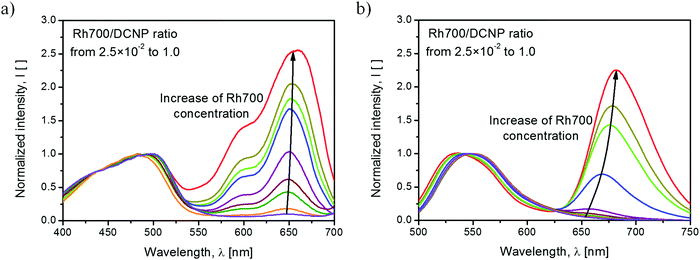
The excitation and emission spectra of the studied polymer films are shown in Fig. 1. In both cases, the excitation and emission intensities were normalized to the maximum intensity of DCNP dye bands. The relatively weak intensity of excitation light (at an excitation wavelength of λexc = 466 nm) provided by the spectrofluorometer resulted in significant molecular emission of DCNP, with hardly noticeable contribution from its aggregates or crystals.18 In the excitation spectra (emission monitored at λem = 720 nm), we can distinguish the band positioned at about 495 nm originated from the molecular form of the DCNP dye, and a few bands associated with the presence of the Rh700 dye, with maxima at about 650 nm, 595 nm and 550 nm (overlapped with the DCNP band tail). It is possible to induce emission from the Rh700 dye by indirect excitation via DCNP molecules, which testifies the radiative and/or nonradiative energy transfer between these two compounds. However, it is worth noting that direct pumping of Rh700 by the second harmonic of the Nd:YAG (λpump = 532 nm) pulsed laser light is also feasible due to the extended Rh700 absorption toward the shorter wavelengths.22 The emission spectra consist of well-distinguishable broadbands associated with the fluorescence of DCNP molecules with the maximum at about 540 nm, and the fluorescence of Rh700 molecules with the maximum at about 670 nm. The occurrence of intermolecular energy transfer is confirmed, as the emission of Rh700 is induced via DCNP excitation. With an increase in the rhodamine acceptor concentration, the DCNP fluorescence band shifts by 11 nm toward shorter wavelengths. We speculate that this might be linked with reabsorption of fluorescence within the layer, as well as due to an increase in the spectral overlap of the emitting pyrazoline (donor) and absorbing rhodamine (acceptor) states, resulting in an even more efficient energy transfer process.7 Simultaneously, the Rh700 emission maximum shifts by about 25 nm to longer wavelengths, which may be connected with reabsorption of its luminescence (the process observed for concentrated luminescent compounds) and partially with the formation of emissive rhodamine dye aggregates, e.g. J-type dimers.23The qualitative difference in the emission profile can be seen after the material excitation at λpump(LD) = 516 nm with the cw laser diode light. The corresponding spectra are shown in Fig. 2. The use of a stronger pumping light source than that provided by a spectrofluorometer lamp results in easily distinguishable emission bands originating from DCNP molecules (blue color), DCNP crystals (yellow color), Rh700 molecules (green color) and, for the higher acceptor dye concentrations, Rh700 aggregates (red color).
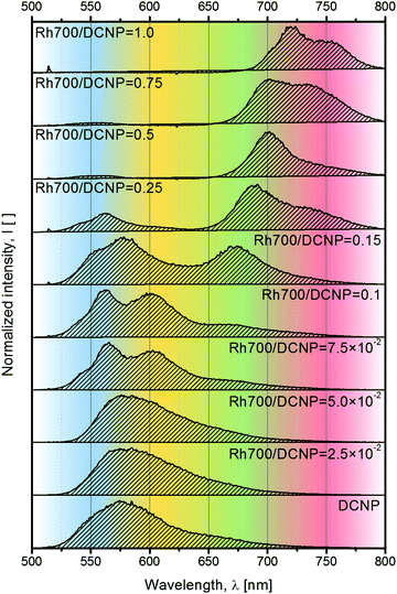 | ||
| Fig. 2 Emission spectra of the studied samples obtained after excitation at λpump(LD) = 516 nm with cw laser diode light. | ||
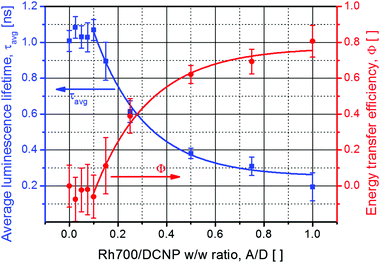
The abovementioned possibility to effectively pump DCNP crystals and to observe their emission allowed us to measure the evolution of their luminescence decays, monitored at λem = 600 nm, for a variable Rh700 dye concentration in the host environment. A few selected luminescence decay curves are shown in Fig. S1 of the ESI.† Relying on the paper concerning the complex origin of DCNP crystal luminescence,17 emission decays were fitted using bi-exponential decay functions. The average luminescence lifetime values were then used for the estimation of energy transfer (resulting in nonradiative DCNP luminescence quenching) efficiencies Φ(A/D) as a function of the A/D ratio, according to the relevant equation taken from FRET theory:24
 | (3) |
The next step in characterization of the gain media concerned studies of the light amplification process upon excitation at λpump = 532 nm with the Nd:YAG nanosecond pulsed laser light. The observed changes in the spectral range and shapes of the luminescence gain profiles with an increase in the acceptor dye content are shown in Fig. 4a. An acceptor-free DCNP/PMMA sample exhibits STE spectra consisting of two maxima, positioned at around 590 nm and 630 nm (blue-shifted band with a smaller intensity due to its origin from the shorter-living trap state17), characteristic uniquely for the pyrazoline dye crystals13 (cf.Fig. 1 showing the DCNP molecular emission). Doping of the gain media with Rh700 results in a gradual spectral broadening of the STE profile. An additional STE band appears on the longer-wavelength side at about 670 nm. The maximum width of the gain profile was recorded for the sample with an A/D ratio equal to 0.15. Therefore, for this material composition, the broadest tuning of the DFB lasing wavelength is expected, despite a noticeable quenching effect (an energy transfer efficiency of about Φ(0.15) = 0.1). A further increase in the A/D ratio causes sudden diminishing of the DCNP STE band intensities as a result of the growing energy transfer influence (with an efficiency of about Φ(0.25) = 0.4) and unavoidable light reabsorption. Simultaneously, a substantial redshift of the Rh700 emission (with the maximum at about 720 nm) can be clearly observed. Such a several dozen nanometer spectral shift is surely connected with the formation of Rh700 aggregates, presumably of the J-type.14 Further addition of the rhodamine dye results in even greater STE band spectral shift toward the infrared, probably due to the formation of higher order J-aggregates, emitting finally at about 750 nm. However, more advanced spectroscopic research supported by quantum-chemical calculations is necessary to unveil their real nature.
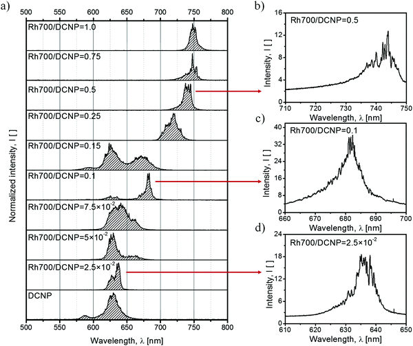 | ||
| Fig. 4 STE spectra reproducing the gain profile for the laser action achieved via 5 ns pulsed laser beam excitation with a stripe-like geometry and at a wavelength of λpump = 532 nm, for samples differing in the relative dye concentration (a). STE along the whole range takes the form of RL (lasing spikes), due to the scattering supported by the DCNP crystals (b–d). Energy densities of the pumping source for the corresponding spectra are listed in Table S2 in the ESI.† | ||
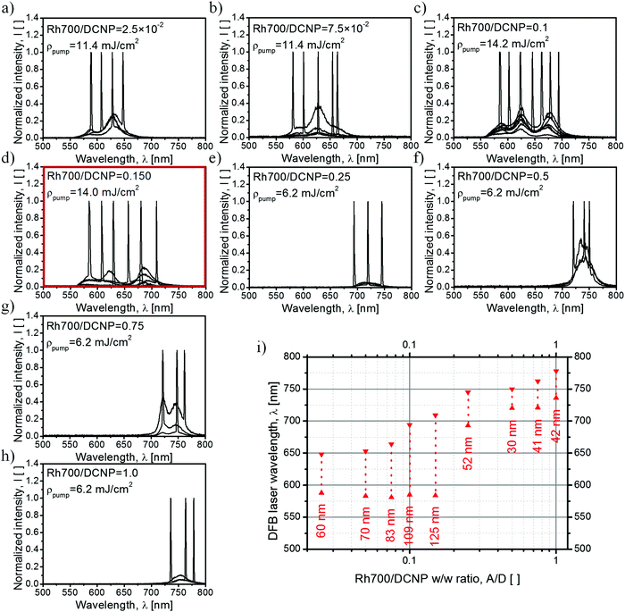
The use of a stripe-like geometry of an excitation area facilitates the observation of the RL phenomenon, if feasible.25 In the case of samples containing DCNP, noticeable irregular shapes of the STE spectra (appearance of spikes) were expected due to the presence of the dye crystals forming resonators or introducing multiple photon scattering within the gain medium and supporting random feedback. In our previous study,13 such crystals a few tens of micrometers in size were responsible for light localization, which was confirmed by comparing sample micrographs below and above the threshold of RL. The exemplary RL spectra measured with a higher spectral resolution are shown in Fig. 4b–d. The bottom spectrum (Fig. 4d) shows the RL occurring within the pyrazoline dye crystal emission band. In the middle part (Fig. 4c), the RL spectrum is attributed to light amplification of the fluorescence of the Rh700 molecules. Because for the sample with an A/D ratio equal to 0.1 there is lack of evident higher order Rh700 aggregates, we can deduce that the DCNP crystals are also responsible for random feedback for the acceptor molecules. In the upper spectrum (Fig. 4b), we can see the RL occurring within the Rh700 bands related to its higher aggregates. In that spectral range, we could expect an additional contribution to the scattering coming from the possible formation of Rh700 nanocrystals, thus influencing the random feedback conditions.26
The studies of DFB lasing wavelength tunability in dye-doped polymeric media were performed with the utilization of a holographic technique enabling simultaneous excitation and temporary resonator formation.27 In order to reduce the possibility of coherent RL occurrence, we have changed the quasi one-dimensional stripe-shaped area of excitation into a circular one. Chosen DFB lasing spectra are presented in Fig. 5a–h. The summary of the DFB lasing experiment is assembled as a dye laser “tuning map” as shown in Fig. 5i. For the lowest Rh700 concentration, tuning is limited to the DCNP STE bands only (Fig. 5a). An increase in the rhodamine dye content results in gradual broadening of the tuning range by an additional band appearing on longer wavelengths, due to the rising contribution of that dye to the overall STE process (Fig. 5b). Further doping with the Rh700 dye enables DFB laser operation within three well-distinguishable STE bands (Fig. 5c), and for an A/D ratio of 0.15 the lasing tuning range reaches the maximum value equal to 125 nm (Fig. 5d), i.e. from λlas = 584 nm to λlas = 709 nm, which is about twice as much as compared to the single dye DCNP/PMMA material.13 Subsequent increase of the rhodamine concentration results in sudden quenching of the DCNP STE bands and further redshift of the Rh700 STE bands (Fig. 5e). Above an A/D ratio of 0.25, the DFB lasing tuning range narrows and becomes dependent on the type and relative contribution of the rhodamine aggregates (Fig. 5e–h). Although in most cases, the presence of the multiband structure is hidden, the spectra for the sample with an A/D ratio of 0.75 (Fig. 5g) exhibit two well-distinguishable bands. Finally, for the sample containing the highest amount of the acceptor dye (Fig. 5h), the gain profile and thus the wavelength tuning range become reduced to only one band at around 750 nm. It can be seen that, detrimental to DFB lasing, light scattering revealed as RL spikes and identified in a previous experiment was successfully suppressed by the superposition of the DFB resonator produced by holographic-type pumping.
The results are in accordance with luminescence lifetime and STE/RL measurements. The acceptor dye content threshold for the occurrence of the energy transfer process designates the limit of undisturbed DCNP crystal utilization in light amplification, while the obtained gain profile range reflects the capability of these materials to improve the lasing tuning performance. For the samples presenting DFB wavelength tunability within the spectral range of the DCNP STE bands, major optical loses encountered for the pyrazoline emitted light could be associated with light reabsorption within the material. We think that randomly distributed Rh700 molecules, at relatively low concentration, are unable to quench fluorescence inside the DCNP crystals. However, an increase in the Rh700 content results in the shortening of the average distance between the absorbing Rh700 molecules and the DCNP crystals. Therefore, above some critical quencher dye concentration, a decrease in DCNP dye luminescence lifetime is observed. In such cases, both processes, i.e. restricted to the DCNP crystal surface resonance energy transfer, as well as reabsorption of emitted photons, are responsible for exclusion of the DCNP contribution to the STE process. Incidentally, taking into consideration the distance range for the occurrence of resonant quenching processes,7 we can intuitively deduce that the larger DCNP crystals should be less susceptible to resonant quenching processes than their smaller versions. However, this statement should be evidenced in the future by further experiments regarding the utilization of higher concentrations of the DCNP compound. On the other hand, the appearance of J-type dimers for higher concentrations of the rhodamine may be connected with accompanying formation of its blue-shifted (in absorption) non-emissive H-type dimers.28,29 H-type aggregates are supposed to quench DCNP crystal emission even more effectively than Rh700 molecules. Finally, the rhodamine dye at a high concentration may absorb the vast part of the pumping light, making efficient excitation of the pyrazoline crystals impossible. However, such comprehensive studies go beyond the scope of this article leaving room for further research.
Conclusions
The detailed spectroscopic studies concerning the DFB lasing tuning ability of polymeric planar waveguides, containing two spectrally separated in terms of emission luminescent dyes with different relative ratios, were performed. It has been shown that utilization of molecular crowding conditions, resulting in the formation of emissive crystals and aggregates of the dyes, can extend the DFB lasing tuning range. The use of DCNP crystals turned out to be especially beneficial for the broadening of the gain profile spectral range. We discovered that a nonradiative energy transfer process, resulting in dye luminescence quenching, plays an important role only after reaching some critical concentration of the Rh700 quencher dye. Therefore, for a certain concentration range of rhodamine, both dyes can be directly excited with the same pumping laser to their population inversion states, which enabled an extremely wide DFB lasing tuning spectral range of 125 nm to be reached. Inherent for the studied materials, the RL phenomenon was suppressed upon coupling of random resonators with the well-defined DFB one. The presented results highlight the advantageous usage of organic gain media for lasing, i.e. their broad range wavelength tuning ability and ease of parameter tailoring, thus showing high application potential. There is still a lot of room for the optimization of the fabrication routes of the subjected lasing system, in order to gain better control over the formation of DCNP crystals and Rh700 aggregates. Finally, in this paper, it was discussed the photophysics of dye-doped materials which should be valuable for the design of any new organic materials for light amplification purposes.Acknowledgements
We would like to thank the Wroclaw University of Science and Technology for the administration support and sharing facilities (Statutory Funds) and the Polish National Science Centre for financial support (grant numbers: 2013/09/D/ST4/03780 and 2016/21/B/ST8/00468).References
- B. B. Snavely, Proc. IEEE, 1969, 57(8), 1374–1390 CrossRef CAS.
- A. J. C. Kuehne and M. C. Gather, Chem. Rev., 2016, 116(21), 12823–12864 CrossRef CAS PubMed.
- I. D. W. Samuel and G. A. Turnbull, Chem. Rev., 2007, 107(4), 1272–1295 CrossRef CAS PubMed.
- S. Chenais and S. Forget, Polym. Int., 2012, 61(3), 390–406 CrossRef CAS.
- O. Mhibik, T. Leang, A. Siove, S. Forget and S. Chenais, Appl. Phys. Lett., 2013, 102(041112), 1–4 Search PubMed.
- Y. Oki, K. Aso, D. Zuo, N. J. Vasa and M. Maeda, Jpn. J. Appl. Phys., Part 1, 2002, 41(11A), 6370–6374 CrossRef CAS.
- Th. Förster, Discuss. Faraday Soc., 1959, 27, 7–17, 10.1039/DF9592700007.
- K. Sonoyama, Y. Takanishi, K. Ishikawa and H. Takezoe, Jpn. J. Appl. Phys., Part 2, 2007, 46(36–40), L874–L876 CrossRef CAS.
- D. Schneider, T. Rabe, T. Riedl, T. Dobbertin, M. Kroger, E. Becker, H. H. Johannes, W. Kowalsky, T. Weimann, J. Wang and P. Hinze, Appl. Phys. Lett., 2004, 85(11), 1886–1888 CrossRef CAS.
- Z. Y. Li, Z. Y. Zhang, A. Scherer and D. Psaltis, Opt. Express, 2006, 14(22), 10494–10499 CrossRef CAS PubMed.
- Z. H. Diao, L. Xuan, L. J. Liu, M. L. Xia, L. F. Hu, Y. G. Liu and J. Ma, J. Mater. Chem. C, 2014, 2(30), 6177–6182 RSC.
- T. R. Zhai, Y. L. Wang, L. Chen, X. F. Wu, S. T. Li and X. P. Zhang, Nanoscale, 2015, 7(47), 19935–19939 RSC.
- K. Parafiniuk, L. Sznitko and J. Mysliwiec, Opt. Lett., 2015, 40(7), 1552–1555 CrossRef CAS PubMed.
- K. Parafiniuk, L. Sznitko, M. Zelechowska and J. Mysliwiec, Org. Electron., 2016, 33, 121–127 CrossRef CAS.
- J. Mysliwiec, L. Sznitko, A. Szukalski, K. Parafiniuk, S. Bartkiewicz, A. Miniewicz, B. Sahraoui, I. Rau and F. Kajzar, Opt. Mater., 2012, 34(10), 1725–1728 CrossRef CAS.
- O. Morawski, B. Kozankiewicz, A. Miniewicz and A. L. Sobolewski, ChemPhysChem, 2015, 16(16), 3500–3510 CrossRef CAS PubMed.
- O. Morawski, A. L. Sobolewski, B. Kozankiewicz, L. Sznitko and A. Miniewicz, Phys. Chem. Chem. Phys., 2014, 16(48), 26887–26892 RSC.
- K. Cyprych, L. Sznitko, O. Morawski, A. Miniewicz, I. Rau and J. Mysliwiec, J. Phys. D: Appl. Phys., 2015, 48(195101), 1–8 CAS.
- M. Fukuda and K. Mito, Jpn. J. Appl. Phys., Part 1, 2000, 39(10), 5859–5863 CrossRef CAS.
- L. Sznitko, J. Mysliwiec, P. Karpinski, K. Palewska, K. Parafiniuk, S. Bartkiewicz, I. Rau, F. Kajzar and A. Miniewicz, Appl. Phys. Lett., 2011, 99(3), 1–3 CrossRef.
- H. Kogelnik and C. V. Shank, Appl. Phys. Lett., 1971, 18(4), 152–154 CrossRef CAS.
- X. M. Guo, Y. Wan, A. D. Xia, S. F. Wang, J. Y. Liu and K. L. Han, Chin. Phys. B, 2009, 18(1), 142–148 CrossRef CAS.
- V. M. Martinez, F. L. Arbeloa, J. B. Prieto and I. L. Arbeloa, J. Phys. Chem. B, 2005, 109(15), 7443–7450 CrossRef CAS PubMed.
- M. Lunz, A. L. Bradley, V. A. Gerard, S. J. Byrne, Y. K. Gun'ko, V. Lesnyak and N. Gaponik, Phys. Rev. B: Condens. Matter Mater. Phys., 2011, 83(115423), 1–10 Search PubMed.
- H. Cao, Y. G. Zhao, S. T. Ho, E. W. Seelig, Q. H. Wang and R. P. H. Chang, Phys. Rev. Lett., 1999, 82(11), 2278–2281 CrossRef CAS.
- P. Hanczyc, L. Sznitko, C. M. Zhong and A. J. Heeger, ACS Photonics, 2015, 2(12), 1755–1762 CrossRef CAS.
- C. V. Shank, J. E. Bjorkholm and H. Kogelnik, Appl. Phys. Lett., 1971, 18(9), 395–396 CrossRef CAS.
- V. M. Martinez, F. L. Arbeloa, J. B. Prieto, T. A. Lopez and I. L. Arbeloa, J. Phys. Chem. B, 2004, 108(52), 20030–20037 CrossRef CAS.
- A. Czimerova, J. Bujdak and N. Iyi, J. Photochem. Photobiol., A, 2007, 187(2–3), 160–166 CrossRef CAS.
Footnote |
| † Electronic supplementary information (ESI) available: Graph of luminescence decay curves of DCNP crystals for selected dye-doped polymers measured at room temperature, a plot presenting deconvolution of biexponential DCNP crystal luminescence decay into two components as a function of relative A/D weight ratios in the samples, a table with relative amplitudes of biexponential DCNP crystal luminescence decay time constants for studied samples, and a table containing pumping light energy densities for the STE spectra shown in Fig. 4 of the main article. See DOI: 10.1039/c7cp02249b |
| This journal is © the Owner Societies 2017 |

