Rational composition and structural design of in situ grown nickel-based electrocatalysts for efficient water electrolysis†
Xiangye
Liu
a,
Xin
Wang
a,
Xiaotao
Yuan
a,
Wujie
Dong
a and
Fuqiang
Huang
*ab
aBeijing National Laboratory for Molecular Sciences and State Key Laboratory of Rare Earth Materials Chemistry and Applications, College of Chemistry and Molecular Engineering, Peking University, Beijing 100871, P. R. China. E-mail: huangfq@pku.edu.cn
bCAS Key Laboratory of Materials for Energy Conversion and State Key Laboratory of High Performance Ceramics and Superfine Microstructures, Shanghai Institute of Ceramics, Chinese Academy of Sciences, Shanghai 200050, P. R. China
First published on 18th November 2015
Abstract
Earth-abundant and highly efficient electrocatalysts for the hydrogen evolution reaction (HER) and oxygen evolution reaction (OER) are desired for water-splitting to produce hydrogen. Some nickel-based materials are usually used in water-alkaline electrolysis, but their composition and structure are still not optimized. In this work, porous aligned flake arrays of Ni-embedded NiO (Ni/NiO) and single-crystalline NiFe layered double hydroxide (LDH) are proposed to be HER and OER electrocatalysts to produce H2 and O2, respectively. The former catalyst, fabricated by non-contact Al-reduction of nickel hydroxide precursors, showed high HER activity, approaching that of commercial Pt/C. The latter catalyst, prepared by the fluorinion-assisted hydrothermal method, possessed higher activity for the OER than the well-known RuO2. The water-alkaline electrolyser assembled by the arrays of Ni/NiO and NiFe LDH in 1 M NaOH exhibits an ultra-small cell voltage of 1.52 V at a current density of 20 mA cm−2 at room temperature, as well as good long-term stabilities. These high performances of our nickel-based arrays result from their improved charge transfer and mass transport, and faster kinetics of catalytic reactions. So the arrays of Ni/NiO and NiFe LDH are promising in the application of water-splitting devices.
Introduction
Hydrogen is one of the most promising alternative energies for the diminishing fossil fuels. Electrolysis of water is a simple and beautiful method for high-purity hydrogen production. Although the supply of water is virtually inexhaustible, water electrolysis has always been economically limited by its high energy consumption (4.5–5 kW h/mn3 H2 for most of the industrial electrolysers).1 Except for the resistance loss through the external circuit and the electrolyte, the large overpotentials of gas evolution on the electrodes are directly responsible for the high cost of water electrolysis.2 Noble metal based materials have been the state-of-art electrocatalysts for their low overpotentials, including Pt, Ru and their alloys for the hydrogen evolution reaction (HER), and IrO2 or RuO2 for the oxygen evolution reaction (OER).3–9 But the scarcity and high cost of those materials limit their large-scale application.Although many earth-abundant HER catalysts (transition metal chalcogenides,10–13 phosphides,14–17 carbides18–20 and nitrides18,20,21) have exhibited high activities in acid solutions approaching Pt, all of them cannot operate satisfactorily in alkaline electrolytes.22 Alkaline HER electrocatalysts are more significant for industrial water-alkali and chlor-alkali electrolyzers. Ni metals and their alloys are typical alkaline electrocatalysts, but they still cannot achieve enough low HER overpotentials and Tafel slopes.2,23–26 Previous research studies have demonstrated that the HER activity of Ni metal can be significantly enhanced by surface modification by NiO or Ni(OH)2, owing to a synergistic effect that HO–H bonds are first efficiently cleaved by nickel oxide species and the derived hydrogen intermediates (Had) are then proficiently converted to H2 by the nearby metallic nickels.9,27,28 However, the coverage and structure of modified oxide species should be elaborately controlled by complicated deposition methods or the carbon nanotube (CNT) assisted reduction method, which are still difficult for the practical application.9,27,28 In contrast, a homogeneous porous nanoscale Ni/NiO array may be an optimal structure for the water-alkaline HER, because it affords a large Ni/NiO interfacial area and excellent bubble management, as well as long-term stability. But it is a challenge to prepare such a homogeneous porous nanoscale array.
For the OER in alkaline media, a great many materials have been tested as promising non-precious electrocatalysts, including 3d oxides, perovskites, spinels, chalcogenides, phosphates.29–34 Among them, Fe-doped nickel oxides and hydroxides have attracted especially intense interest owing to their superior OER activity comparable to RuO2 and IrO2.34–39 In particular, the amorphous binder-free NiFe layered double hydroxide (LDH) on Ni foam has the advantages of long-term stability and larger surface area.40 The previously-reported samples are randomly-stacked NiFe LDH films on a certain 3D substrate, whose microstructure is not optimal for charge and mass transfer.40–42 Furthermore, the amorphous structure of very poor electric conductors is especially bad for carbon-free oxide electrodes. Crystalline NiFe LDH has been evidenced to outperform amorphous NiFe oxides.37 Therefore, single-crystalline NiFe LDH porous aligned arrays in situ grown on 3D substrates should be better for charge transfer and bubble management to afford an enhanced OER activity.
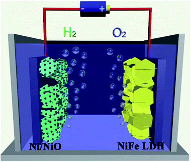
Here, we report porous aligned flake arrays of Ni-embedded NiO (Ni/NiO) and single-crystalline NiFe LDH as two electrocatalysts in a water-alkaline electrolyzer, as illustrated in Fig. 1. The aims of this design are listed as follows: (i) the uniformly distributed Ni nanoparticles with the neighboring NiO species can exert good synergetic effects to efficiently convert water molecules to H2; (ii) the porous arrays are in good contact with the current collector, which is very beneficial to the charge transfer and mass transport (inward diffusion of the electrolyte and outwards diffusion of gas bubbles), as well as long-term stability; (iii) Ni metal particles and single-crystalline NiFe LDH further improve the electric conductivity of the electrodes. Electrochemical measurements showed that the flake arrays exhibited high catalytic abilities for the HER and OER, and low voltages for water electrolysis with excellent long-term stabilities. So they are promising materials for large-scale hydrogen production from water-splitting.
Results and discussion
Porous Ni/NiO nanocomposite array on Ni foam for HER
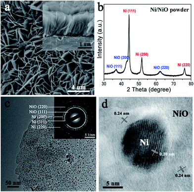
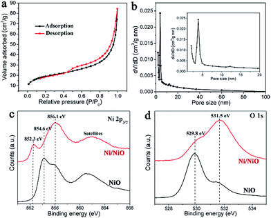
Oriented Ni(OH)2·0.75H2O nanoflake arrays on nickel foam were first prepared by a hydrothermal method, confirmed by the X-ray diffraction (XRD) and scanning electron microscopy (SEM) results (Fig. S1†).43 Then they were treated by a non-contact Al-reduction process in a vacuum two-zone tube furnace, in order to obtain the desired nanoscale Ni/NiO flake arrays.44 The SEM image and the cross-sectional analysis (Fig. 2a) indicate that the Ni/NiO on Ni foam remains the aligned array structures and each Ni/NiO flake unit is in vertical contact with the substrate. The XRD result of the corresponding Ni/NiO powder reveals the co-existence of the cubic Ni and NiO, with the same indices of (111), (200) and (220), as shown in Fig. 2b. The intense peaks of Ni indicate a good crystallinity, with the average crystalline size of ∼10 nm calculated from the Scherrer equation. By contrast, NiO is formed with a low crystallinity, seen from the weak and widened XRD signals, indicating a defective crystal structure. The transmission electron microscopy (TEM) image (Fig. 2c) shows that the Ni/NiO sample has a thin layered nanosheet structure, composed of opaque nanodots that are uniformly connected by the light fine plates. The high-resolution transmission electron microscopy (HRTEM) image of the opaque particles (Fig. 2d) reveals an interplanar spacing of 0.20 nm that is consistent with the d-spacing of (111) planes of cubic Ni. And the surrounding plates exhibit little random lattice fringes with an interplanar spacing of about 0.24 nm, which correspond to the (111) planes of a cubic-phase NiO. The corresponding SAED patterns (inset of Fig. 2c) indicate that the metallic Ni is highly crystallized whereas the oxide species have a poor crystallinity, consistent with the XRD results. Moreover, numerous inter-particle mesopores with sizes ranging from 2 to 5 nm in these flakes can be clearly seen (Fig. 2c). These pores are probably originated from the release of water and oxygen molecules during the reduction process that converts Ni(OH)2 to Ni/NiO nanoparticles.The pore structures of mesoporous Ni/NiO were examined by N2 adsorption–desorption measurements. The isotherms with H3 hysteresis loops were observed for our Ni/NiO (Fig. 3a), which are commonly observed for plate-like particles with slit-shaped pores.43,45 The pore size distributions calculated from the desorption isotherms by the BJH method are shown as a plot of the relative pore filling versus pore size in Fig. 3b. It indicates that mesopores with a size of 2–50 nm are in the Ni/NiO flakes, with the main peak at 3.8 nm. This is in accordance with the TEM results. It is well known that the nanoporous structures are important to facilitate mass transport of electrolytes and gas bubbles, and will also provide a large electroactive area for the electrochemical reaction.46
X-ray photoelectron spectroscopy (XPS) was performed in order to study the defective NiO species in the Ni/NiO hybrids. Compared to the Ar-annealed NiO sample of three typical NiII peaks, respectively, at 854.6 eV (main peak), 856.1 eV (shoulder peak) and 861.5 eV (satellites), the spectrum of the Ni/NiO sample shows an extremely intense shoulder peak at 856.1 eV, with an additional metallic Ni peak at 852.3 eV, as displayed in Fig. 3c. It is evidenced that the shoulder peak at 856.1 eV for NiO is attributed to a non-local screening effect, where Ni atoms are screened by the non-local coordinated O atoms, consistent with the literature oxygen-defective structures.47–49 Thus, it is rational to point out that the Ni/NiO sample is dominated by oxygen-defective NiOx species, consistent with the low-crystallinity feature seen from XRD and SAED. Apparently, these oxygen deficiencies result from the Al reduction to afford active centers to efficiently cleave water molecules.50,51 Additionally, the oxygen vacancies in Ni/NiO cause large amounts of surface hydroxyl groups,51 seen from its extremely stronger peak at 531.5 eV than that of Ar–NiO in the O 1s XPS (Fig. 3d). These surface hydroxyl groups make a more hydrophilic electrode surface, facilitating the electrolyte to infiltrate into the nanopores of the electrode. Furthermore, surface hydroxyl groups could participate in the catalytic reactions of water cleavage.52
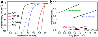
The HER catalytic property of the Ni/NiO array was measured in a three-electrode configuration in 1 M NaOH with a scan rate of 1 mV s−1. Ni metal, NiO and commercial Pt/C were also investigated under the same conditions for comparison. The Ni metal electrode and NiO electrode were obtained from the same precursor Ni(OH)2·0.75H2O/Ni foam annealed in a H2/Ar or Ar atmosphere, respectively. The corresponding XRD of the powder sample is shown in Fig. S2.†Fig. 4a shows the electropolarization curves. The Ni/NiO array exhibits excellent HER activity with a near-zero onset overpotential as the same as the Pt/C, much better than that of the Ni electrode (onset overpotential of 120 mV) and NiO electrode (onset overpotential of 290 mV). The Ni/NiO array requires overpotentials of 46, 92 and 137 mV to afford current densities of 20, 50 and 100 mA cm2, which are just 29, 54 and 65 mV larger than the Pt/C electrode, respectively. These overpotentials are smaller than those of other reported HER electrodes at the same current density measured in alkaline media, including Raney Ni,25 Ni–Mo alloy,23 Ni(OH)2 modified Ni metal,28 and comparable to the CNT-Ni/NiO.27 Our Ni/NiO array electrode even exhibited smaller HER overpotentials than those star catalysts measured in acid electrolytes, such as FeP,16 NiP,15,53 CoP,54 CuP,17 CoSe2,13 MoS2,55 WS2,56 Mo2N18 and Mo2C.19 Furthermore, the Ni/NiO array exhibits an extremely small Tafel slope of 65 mV per dec in the overpotential region of 0–56 mV, which is much smaller than that of the Ni electrode (115 mV per dec) and NiO electrode (151 mV per dec), as shown in Fig. 4b.
It is well known that the mechanism of the HER in alkaline media is a combination of three elementary steps: the Volmer step, where water dissociation and formation of a reactive intermediate Had (2H2O + M + 2e− ⇆ 2M–Had + 2OH−), followed by either the Heyrovsky step (H2O + Had–M + e− ⇆ M + H2 + OH−) or the Tafel recombination step (2M–Had ⇆ 2M + H2). The first Volmer step is the rate-determining step.9 Water dissociation on the pure Ni surface and Had absorption on the NiO surface are all kinetically difficult, which accounts for the comparably larger Tafel slopes of the Ni and NiO electrodes. For the Ni/NiO array electrode, water adsorption requires concerted interaction of O atoms with NiO and H atoms with Ni at their boundaries. Water adsorption is then followed by HO–H cleavage and Had formation at the nearby Ni site. Finally, two Had atoms on the Ni surface recombine to form H2 and OH− desorbs from the NiO domains, followed by adsorption of another water molecule at the same site.9 Thus the rate-determining Volmer step was hugely accelerated in the Ni/NiO electrode, which accounts for its extremely small Tafel slope. Therefore, the superior HER activity of the Ni/NiO array electrode is attributed to: (i) the porous arrays that are in good contact with the current collector, benefitting the mass transport and charge transfer; (ii) metallic Ni nanoparticles further improving the electric conductivity of the electrodes; and (iii) the synergistic effect at the Ni/NiO interface facilitating HER kinetics.
Single-crystalline NiFe LDH array on Ni foam for OER
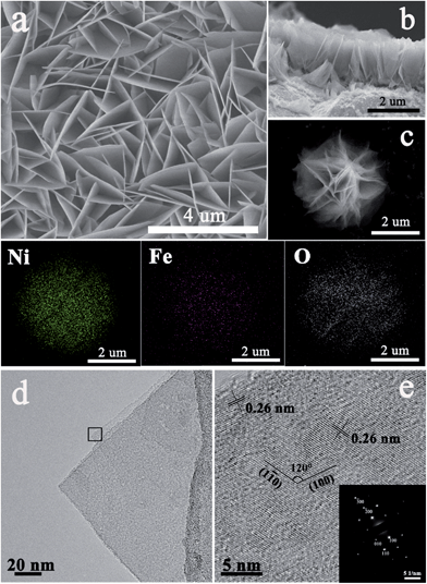
The single-crystalline NiFe LDH array on a Ni foam was prepared by a facile hydrothermal growth method with assistance of a direction agent of NH4F.43,57 The as-grown NiFe LDH array shows the XRD diffraction peaks at 11.4°, 22.9°, 33.5°, 34.4°, 39.0°, 60.0° and 61.2°, as shown in Fig. S3,† which are well indexed to the (003), (006), (101), (012), (015), (110) and (113) reflections of a trigonal NiFe LDH structure (JCPDS card no. 38-0715). Both the SEM (Fig. 5a) and cross-sectional images of the NiFe LDH array (Fig. 5b) reveal a highly oriented flake array structure that are in vertical contact with the substrate with macropores existing between the connected flakes. Each flake has an edge length of 1–3 μm and a uniform thickness of less than 20 nm. The corresponding elemental mapping of the flower-like NiFe LDH powder (Fig. 5c) displays a very uniform intensity distribution of Ni and Fe with a mole ratio of Ni![[thin space (1/6-em)]](https://www.rsc.org/images/entities/char_2009.gif) :
:![[thin space (1/6-em)]](https://www.rsc.org/images/entities/char_2009.gif) Fe ∼ 9 (Fig. S4†), revealing a homogeneous chemical composition of the NiFe LDH layer. The TEM image in Fig. 5d shows a NiFe LDH flake stacked by 3–5 atomic layers. Each NiFe LDH layer is a single crystal with the symmetry of theR
Fe ∼ 9 (Fig. S4†), revealing a homogeneous chemical composition of the NiFe LDH layer. The TEM image in Fig. 5d shows a NiFe LDH flake stacked by 3–5 atomic layers. Each NiFe LDH layer is a single crystal with the symmetry of theR![[3 with combining macron]](https://www.rsc.org/images/entities/char_0033_0304.gif) m space group, as derived from the SAED patterns (inset of Fig. 5e). The HRTEM image of the NiFe LDH layer shows an interplanar distance of 0.26 nm, consistent with the (100) and (1
m space group, as derived from the SAED patterns (inset of Fig. 5e). The HRTEM image of the NiFe LDH layer shows an interplanar distance of 0.26 nm, consistent with the (100) and (1![[1 with combining macron]](https://www.rsc.org/images/entities/char_0031_0304.gif) 0) planes which are parallel to the c axis with an interfacial angle of 120° (Fig. 5e).
0) planes which are parallel to the c axis with an interfacial angle of 120° (Fig. 5e).
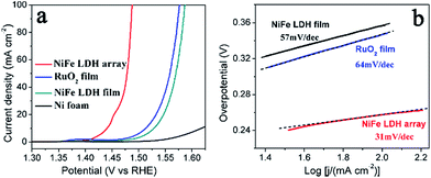
The OER catalytic properties of the NiFe LDH array were evaluated in a three-electrode configuration in 1 M NaOH with a scan rate of 1 mV s−1, as shown in Fig. 6a. The NiFe LDH film and RuO2 film coated on Ni foams as two references were also investigated for comparison. The NiFe LDH array exhibits outstanding OER activity, achieving the overpotentials of 210 mV, 240 mV and 260 mV at the current densities of 10, 50 and 100 mA cm2, respectively. These overpotentials are much smaller than those of the coated NiFe LDH film, indicating the advantage of the in situ grown NiFe LDH array. The NiFe LDH array also outperforms the RuO2 film electrode (280 mV at 10 mA cm2, 320 mV at 50 mA cm2 and 350 mV at 100 mA cm2). Our single-crystalline NiFe LDH arrays exhibit smaller overpotentials than the reported results from amorphous NiFe materials34,40 and other analogous LDH-based materials.36–38,58–60 Additionally, an impressively small Tafel slope of the NiFe LDH array was observed to be 31 mV per dec in the overpotential region of 240–260 mV, which is smaller than those of NiFe LDH film (57 mV per dec) and RuO2 film (64 mV per dec), as shown in Fig. 6b. A smaller Tafel slope implies a faster OER kinetics and a large catalytic current density at low overpotentials.
Similar to the Ni/NiO array for the HER, the superior OER activity of the NiFe LDH array electrode is attributed to (i) its porous aligned array structure in favour of efficient mass transport and (ii) the fact that each NiFe LDH single-crystal flake is in good contact with the current collector efficiently facilitating charge transfer during OER and thus improving the OER kinetics. These two factors account for the significantly enhanced OER activity of the NiFe LDH array compared to the coated NiFe LDH film.
Water electrolysis by arrays of Ni/NiO and NiFe LDH
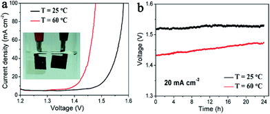
An electrolyzer is assembled using the Ni/NiO array as the cathode and the NiFe LDH array as the anode in the electrolyte of 1 M NaOH, and the photograph is shown in the inset of Fig. 7a. For water electrolysis at room temperature (25 °C), current densities of 20 mA cm−2 at 1.52 V and 100 mA cm−2 at 1.58 V were observed. This performance is comparable to the previously reported CNT-Ni/NiO–NiFe LDH cell and extremely outstanding for the non-precious electrocatalysts such as Ni-based alloy cells2,19 and the recent Co–CoOx/N-doped carbon cells.61 The kinetics and thermodynamics were further improved at a higher temperature. Lower voltages of 1.43 V at 20 mA cm−2 and 1.48 V at 100 mA cm−2 are achieved at 60 °C, seen from Fig. 7a. Long-term stability is another essential quality for a practical electrolyzer. So the durability of our electrolyzer was measured at 20 mA cm−2 at different temperatures. After running for 24 h, the water electrolysis voltage remains the same as the initial value at 25 °C, and slightly increases by 3.2% for the 60 °C measurement, shown in Fig. 7b. These results suggest good stability of our array electrodes, which is better than the reported bindered CNT-Ni/NiO/Ni foam and NiFe LDH/Ni foam electrodes. And the increase in the cell voltage for the measurement at 60 °C is mainly resulted from the loss of electrolyte and the existence of lots of bubbles at the electrolyte surface after long-term water electrolysis. The well-aligned arrays of Ni/NiO and NiFe LDH match the benchmark precious catalysts, and pave a new pathway for designing cost-effective water-splitting devices.Conclusions
In summary, we prepared porous well-aligned nanoscale Ni/NiO flake arrays and single crystalline NiFe LDH flake arrays in situ grown on Ni foam, as highly efficient electrocatalysts for the HER and OER, respectively. By rational composition and structural design, our nickel-based electrodes were improved in the properties of charge transfer, mass transport and kinetics of catalytic reactions. The water-alkaline electrolyzer assembled by the arrays of Ni/NiO and NiFe LDH in 1 M NaOH achieved 20 mA cm−2 with an ultra-small cell voltage of 1.52 V at 25 °C and 1.43 V at 60 °C, respectively, as well as good durability. To our knowledge, this is scarcely-reported outstanding performance for water electrolysis based on non-precious electrocatalysts. These highly active nickel-based electrocatalysts are much promising for the application of low-cost water-splitting devices.Acknowledgements
This work was financially supported from NSF of China (Grant no. 61376056, 51125006, and 91122034), and Science and Technology Commission of Shanghai (Grant no. 13JC1405700, and 14520722000).Notes and references
- D. L. Stojić, M. P. Marčeta, S. P. Sovilj and Š. S. Miljanić, J. Power Sources, 2003, 118, 315–319 CrossRef.
- K. Zeng and D. Zhang, Prog. Energy Combust. Sci., 2010, 36, 307–326 CrossRef CAS.
- M. G. Walter, E. L. Warren, J. R. McKone, S. W. Boettcher, Q. Mi, E. A. Santori and N. S. Lewis, Chem. Rev., 2010, 110, 6446–6473 CrossRef CAS PubMed.
- Y. Zheng, Y. Jiao, M. Jaroniec and S. Z. Qiao, Angew. Chem., Int. Ed., 2015, 54, 52–65 CrossRef CAS PubMed.
- V. I. Birss and A. Damjanovic, J. Electrochem. Soc., 1987, 134, 113–117 CrossRef CAS.
- Y. Lee, J. Suntivich, K. J. May, E. E. Perry and Y. Shao-Horn, J. Phys. Chem. Lett., 2012, 3, 399–404 CrossRef CAS PubMed.
- E. J. O'Sullivan and L. D. Burke, J. Electrochem. Soc., 1990, 137, 466–471 CrossRef.
- J. D. Blakemore, N. D. Schley, G. W. Olack, C. D. Incarvito, G. W. Brudvig and R. H. Crabtree, Chem. Sci., 2011, 2, 94–98 RSC.
- R. Subbaraman, D. Tripkovic, D. Strmcnik, K.-C. Chang, M. Uchimura, A. P. Paulikas, V. Stamenkovic and N. M. Markovic, Science, 2011, 334, 1256–1260 CrossRef CAS PubMed.
- S. Peng, L. Li, X. Han, W. Sun, M. Srinivasan, S. G. Mhaisalkar, F. Cheng, Q. Yan, J. Chen and S. Ramakrishna, Angew. Chem., Int. Ed., 2014, 53, 12594–12599 CAS.
- J. Kibsgaard, T. F. Jaramillo and F. Besenbacher, Nat. Chem., 2014, 6, 248–253 CrossRef CAS PubMed.
- Y. H. Chang, C. T. Lin, T. Y. Chen, C. L. Hsu, Y. H. Lee, W. Zhang, K. H. Wei and L. J. Li, Adv. Mater., 2013, 25, 756–760 CrossRef CAS PubMed.
- D. Kong, H. Wang, Z. Lu and Y. Cui, J. Am. Chem. Soc., 2014, 136, 4897–4900 CrossRef CAS PubMed.
- E. J. Popczun, C. G. Read, C. W. Roske, N. S. Lewis and R. E. Schaak, Angew. Chem., 2014, 126, 5531–5534 CrossRef.
- E. J. Popczun, J. R. McKone, C. G. Read, A. J. Biacchi, A. M. Wiltrout, N. S. Lewis and R. E. Schaak, J. Am. Chem. Soc., 2013, 135, 9267–9270 CrossRef CAS PubMed.
- P. Jiang, Q. Liu, Y. Liang, J. Tian, A. M. Asiri and X. Sun, Angew. Chem., Int. Ed., 2014, 53, 12855–12859 CrossRef CAS PubMed.
- J. Tian, Q. Liu, N. Cheng, A. M. Asiri and X. Sun, Angew. Chem., Int. Ed., 2014, 53, 9577–9581 CrossRef CAS PubMed.
- D. H. Youn, S. Han, J. Y. Kim, J. Y. Kim, H. Park, S. H. Choi and J. S. Lee, ACS Nano, 2014, 8, 5164–5173 CrossRef CAS PubMed.
- W.-F. Chen, C.-H. Wang, K. Sasaki, N. Marinkovic, W. Xu, J. Muckerman, Y. Zhu and R. Adzic, Energy Environ. Sci., 2013, 6, 943–951 CAS.
- W.-F. Chen, J. T. Muckerman and E. Fujita, Chem. Commun., 2013, 49, 8896–8909 RSC.
- W. F. Chen, K. Sasaki, C. Ma, A. I. Frenkel, N. Marinkovic, J. T. Muckerman, Y. Zhu and R. R. Adzic, Angew. Chem., Int. Ed., 2012, 51, 6131–6135 CrossRef CAS PubMed.
- M. S. Faber and S. Jin, Energy Environ. Sci., 2014, 7, 3519–3542 CAS.
- J. R. McKone, B. F. Sadtler, C. A. Werlang, N. S. Lewis and H. B. Gray, ACS Catal., 2013, 3, 166–169 CrossRef CAS.
- N. Krstajić, V. Jović, L. Gajić-Krstajić, B. Jović, A. Antozzi and G. Martelli, Int. J. Hydrogen Energy, 2008, 33, 3676–3687 CrossRef.
- E. Endoh, H. Otouma, T. Morimoto and Y. Oda, Int. J. Hydrogen Energy, 1987, 12, 473–479 CrossRef CAS.
- B. Tilak, A. Ramamurthy and B. Conway, Proceedings of the Indian Academy of Sciences-Chemical Sciences, 1986, 97, 359–393 CAS.
- M. Gong, W. Zhou, M. C. Tsai, J. Zhou, M. Guan, M. C. Lin, B. Zhang, Y. Hu, D. Y. Wang, J. Yang, S. J. Pennycook, B. J. Hwang and H. Dai, Nat. Commun., 2014, 5, 4695 CrossRef CAS PubMed.
- N. Danilovic, R. Subbaraman, D. Strmcnik, K. C. Chang, A. Paulikas, V. Stamenkovic and N. M. Markovic, Angew. Chem., 2012, 124, 12663–12666 CrossRef.
- I. Katsounaros, S. Cherevko, A. R. Zeradjanin and K. J. Mayrhofer, Angew. Chem., Int. Ed., 2014, 53, 102–121 CrossRef CAS PubMed.
- M. Gong and H. Dai, Nano Res., 2015, 8, 23–39 CrossRef CAS.
- R. Subbaraman, D. Tripkovic, K.-C. Chang, D. Strmcnik, A. P. Paulikas, P. Hirunsit, M. Chan, J. Greeley, V. Stamenkovic and N. M. Markovic, Nat. Mater., 2012, 11, 550–557 CrossRef CAS PubMed.
- M. W. Kanan and D. G. Nocera, Science, 2008, 321, 1072–1075 CrossRef CAS PubMed.
- J. Suntivich, K. J. May, H. A. Gasteiger, J. B. Goodenough and Y. Shao-Horn, Science, 2011, 334, 1383–1385 CrossRef CAS PubMed.
- R. D. Smith, M. S. Prévot, R. D. Fagan, Z. Zhang, P. A. Sedach, M. K. J. Siu, S. Trudel and C. P. Berlinguette, Science, 2013, 340, 60–63 CrossRef CAS PubMed.
- K. Fominykh, P. Chernev, I. Zaharieva, J. Sicklinger, G. Stefanic, M. Döblinger, A. Müller, A. Pokharel, S. Böcklein and C. Scheu, ACS Nano, 2015, 9, 5180–5188 CrossRef CAS PubMed.
- F. Song and X. Hu, Nat. Commun., 2014, 5, 1–9 Search PubMed.
- M. Gong, Y. Li, H. Wang, Y. Liang, J. Z. Wu, J. Zhou, J. Wang, T. Regier, F. Wei and H. Dai, J. Am. Chem. Soc., 2013, 135, 8452–8455 CrossRef CAS PubMed.
- D. Tang, J. Liu, X. Wu, R. Liu, X. Han, Y. Han, H. Huang, Y. Liu and Z. Kang, ACS Appl. Mater. Interfaces, 2014, 6, 7918–7925 CAS.
- X. Long, J. Li, S. Xiao, K. Yan, Z. Wang, H. Chen and S. Yang, Angew. Chem., 2014, 126, 7714–7718 CrossRef.
- X. Lu and C. Zhao, Nat. Commun., 2015, 6, 1–7 Search PubMed.
- J. Luo, J.-H. Im, M. T. Mayer, M. Schreier, M. K. Nazeeruddin, N.-G. Park, S. D. Tilley, H. J. Fan and M. Grätzel, Science, 2014, 345, 1593–1596 CrossRef CAS PubMed.
- Z. Lu, W. Xu, W. Zhu, Q. Yang, X. Lei, J. Liu, Y. Li, X. Sun and X. Duan, Chem. Commun., 2014, 50, 6479–6482 RSC.
- H. Wu, M. Xu, H. Wu, J. Xu, Y. Wang, Z. Peng and G. Zheng, J. Mater. Chem., 2012, 22, 19821–19825 RSC.
- Z. Wang, C. Yang, T. Lin, H. Yin, P. Chen, D. Wan, F. Xu, F. Huang, J. Lin and X. Xie, Energy Environ. Sci., 2013, 6, 3007–3014 CAS.
- X. Zhang, W. Shi, J. Zhu, W. Zhao, J. Ma, S. Mhaisalkar, T. L. Maria, Y. Yang, H. Zhang and H. H. Hng, Nano Res., 2010, 3, 643–652 CrossRef CAS.
- X. Lu and C. Zhao, Nat. Commun., 2015, 6, 6616 CrossRef CAS PubMed.
- L. Soriano, I. Preda, A. Gutiérrez, S. Palacín, M. Abbate and A. Vollmer, Phys. Rev. B: Condens. Matter Mater. Phys., 2007, 75, 233417 CrossRef.
- D. Alders, F. Voogt, T. Hibma and G. Sawatzky, Phys. Rev. B: Condens. Matter Mater. Phys., 1996, 54, 7716 CrossRef CAS.
- M. Van Veenendaal and G. Sawatzky, Phys. Rev. Lett., 1993, 70, 2459 CrossRef CAS PubMed.
- Y. Wang, T. Zhou, K. Jiang, P. Da, Z. Peng, J. Tang, B. Kong, W. B. Cai, Z. Yang and G. Zheng, Adv. Energy Mater., 2014, 4, 1–7 Search PubMed.
- J. M. McKay and V. E. Henrich, Phys. Rev. B: Condens. Matter Mater. Phys., 1985, 32, 6764 CrossRef CAS.
- Y.-F. Li and A. Selloni, ACS Catal., 2014, 4, 1148–1153 CrossRef CAS.
- Z. Pu, Q. Liu, C. Tang, A. M. Asiri and X. Sun, Nanoscale, 2014, 6, 11031–11034 RSC.
- J. Tian, Q. Liu, A. M. Asiri and X. Sun, J. Am. Chem. Soc., 2014, 136, 7587–7590 CrossRef CAS PubMed.
- M. A. Lukowski, A. S. Daniel, F. Meng, A. Forticaux, L. Li and S. Jin, J. Am. Chem. Soc., 2013, 135, 10274–10277 CrossRef CAS PubMed.
- D. Voiry, H. Yamaguchi, J. Li, R. Silva, D. C. Alves, T. Fujita, M. Chen, T. Asefa, V. B. Shenoy and G. Eda, Nat. Mater., 2013, 12, 850–855 CrossRef CAS PubMed.
- J. Jiang, J. P. Liu, X. T. Huang, Y. Y. Li, R. M. Ding, X. X. Ji, Y. Y. Hu, Q. B. Chi and Z. H. Zhu, Cryst. Growth Des., 2010, 10, 70–75 CAS.
- S. Chen, J. Duan, M. Jaroniec and S. Z. Qiao, Angew. Chem., Int. Ed., 2013, 52, 13567–13570 CrossRef CAS PubMed.
- J. Nai, H. Yin, T. You, L. Zheng, J. Zhang, P. Wang, Z. Jin, Y. Tian, J. Liu and Z. Tang, Adv. Energy Mater., 2015, 5, 1–7 Search PubMed.
- F. Song and X. Hu, J. Am. Chem. Soc., 2014, 136, 16481–16484 CrossRef CAS PubMed.
- H. Jin, J. Wang, D. Su, Z. Wei, Z. Pang and Y. Wang, J. Am. Chem. Soc., 2015, 137, 2688–2694 CrossRef CAS PubMed.
Footnote |
| † Electronic supplementary information (ESI) available: The experimental section, the SEM image of Ni(OH)2·0.75H2O nanoflake arrays on Ni foam, the XRD patterns of Ni(OH)2·0.75H2O nanoflake arrays on Ni foam, Ni and NiO powder, and the single-crystalline NiFe LDH flake arrays on Ni foam, and the energy dispersive X-ray spectrum of NiFe LDH powder. See DOI: 10.1039/c5ta07047c |
| This journal is © The Royal Society of Chemistry 2016 |

