DOI:
10.1039/C5TA06962A
(Review Article)
J. Mater. Chem. A, 2016,
4, 32-50
Strategies to succeed in improving the lithium-ion storage properties of silicon nanomaterials
Received
2nd September 2015
, Accepted 19th November 2015
First published on 19th November 2015
Abstract
Silicon is of scientific and practical interest in lithium-ion batteries (LIBs) due to its natural abundance, low toxicity, moderate working potential, and high theoretical capacity. However, its huge volume variation during lithiation and delithiation processes leads to the pulverization of silicon particles and subsequently results in fast capacity fade of the electrodes. Furthermore, the intrinsic electric conductivity of Si is relatively low and lithium diffusion in Si is rather slow. These issues hinder the practical application of Si in LIBs. In the past decade, significant improvements in the anode's cycleability and rate capability have been achieved by the control of the nanostructure and morphology of the Si electrode and incorporation of conductive species. In this review, the preparation methods and electrochemical performance of these Si electrode nanomaterials are summarised. The mechanisms behind the performance enhancement are illustrated. Moreover, factors that affect the performance of Si anodes, such as electrolyte additives, binders, and current collectors, are also discussed. We aim to shed some light on some emerging directions for future research on Si anodes in LIBs.
 Fei-Hu Du | Fei-Hu Du received his BS degree (2008) and MS degree (2011) in inorganic chemistry from the Jiangsu University. He obtained his PhD degree from the School of Chemistry and Chemical Engineering at Shanghai Jiao Tong University in 2015. His research interest is primarily focused on inorganic materials, particularly on silicon-based electrode materials for Li ion batteries. |
 Kai-Xue Wang | Prof. Kai-Xue Wang obtained his PhD degree in inorganic chemistry from the Jilin University in 2002. He worked as a postdoctoral researcher at the University College Cork, Ireland and then JSPS research fellow at the National Institute of Advanced Industrial Science and Technology, Japan from 2003 to 2009. Since 2009, he has been a professor in the School of Chemistry and Chemical Engineering, Shanghai Jiao Tong University. His research mainly focuses on the design and preparation of functional materials for energy storage and conversion. |
 Jie-Sheng Chen | Prof. Jie-Sheng Chen received his PhD degree from the Jilin University in 1989 and worked as a postdoctoral fellow in the Royal Institution of Great Britain, the United Kingdom, from 1990 to 1994, and as a professor in the Department of Chemistry, Jilin University from 1994 to 2008. He has been a professor in the School of Chemistry and Chemical Engineering, Shanghai Jiao Tong University from 2008. His research interest is the synthesis of solid compounds and composite materials with new structures and functions. |
1. Introduction
The increasing depletion of non-renewable fossil fuels and the greenhouse gas emissions have aroused intense interest in exploring environmentally friendly energy resources (EERs).1,2 However, most EERs, such as wind and solar energy, are intermittent, and hence highly efficient energy storage devices are required.3 In this regard, lithium-ion batteries (LIBs) with relatively high energy and power densities can play a critically important role in the practical utilization of such EERs. LIBs have also been regarded as ideal power sources for electric vehicles (EVs) and hybrid electric vehicles (HEVs).4 As a key component, electrode materials play an important role in the electrochemical performance of LIBs. Currently, graphite with a theoretical capacity of only 372 mA h g−1 is used as the anode material in commercial LIBs.5 To satisfy the demand of EERs, EVs and HEVs for LIBs with high energy and power densities, considerable efforts have been devoted to alloy-type anodes with high theoretical capacity, including silicon,5 phosphorus,6–8 germanium,9,10 and tin.11–16
Among all alloy-type anodes, Si has a large theoretical capacity (4200 mA h g−1 by forming Li22Si5) and low discharge potential (∼370 mV vs. Li/Li+), leading to high energy densities of batteries.17 Si is the second-most abundant element in the earth's crust and also environmentally benign. In addition, the semiconductor industry has a mature technology for large-scale production of Si. Because of these advantages, Si has been regarded as one of the most promising candidates for LIB anodes. Unfortunately, its large volume change (>300%) during cycling induces severe cracking of Si, electrical disconnection of the active materials from the current collector, as well as formation of an unstable solid electrolyte interphase (SEI) on the Si surface, consequently leading to fast capacity fade of the electrodes. Moreover, the slow lithium diffusion kinetics in Si (diffusion coefficient between 10−14 and 10−13 cm2 s−1) and the low intrinsic electric conductivity of Si (∼10−3 S cm−1) significantly affect the rate capability and the full capacity utilization of Si electrodes.18 These issues have to be addressed before the practical application of Si electrodes.
Recently, strategies such as the generation of nanostructures, surface modification, addition of electrolyte additives, development of novel polymer binders, and selection of appropriate current collectors have been developed and proved to be efficient in improving the electrochemical performance of Si electrodes. Considerable efforts have been devoted to the generation of a variety of Si nanostructures, such as thin films, nanosheets, nanorods, nanotubes, and porous structures. Nanostructures have several advantages over bulk ones. (1) Nanostructures can relax the mechanical strain and effectively accommodate the volume variation during lithiation and delithation processes, maintaining high specific capacity with a significantly improved cycle life. (2) Nanostructures can provide a much higher active surface area, permitting rapid interfacial Li+ diffusion. (3) Nanostructures may shorten the diffusion distance for Li+, ensuring reduced polarization and improved rate capability.18,19 The incorporation of conductive species, such as carbonaceous materials, metals, and conductive polymers, has also been frequently employed to improve the electric conductivity, rate capability and cycling stability of Si electrode materials. In order to improve the performance of Si electrodes, electrolyte additives, binders, and current collectors involved in the electrode generation should also be considered. The addition of appropriate additives would control the formation of thin and stable SEI layers, reducing the consumption of extra electrolyte upon cycling and consequently leading to better cycling stability. Polymer binders are usually mixed with active materials and conductive additives to form slurries and help to form relatively homogeneous and stable coatings on current collectors. The selection of appropriate polymer binders would enhance the integrity of Si electrodes. In addition, current collectors with porous structures and rough surfaces are also essential to ensure good electric contact between active materials and current collectors.
In this review, we summarize the strategies developed recently for improving the electrochemical performance of these Si materials. The focus of this review is the recent progress in the controlled preparation of Si nanostructures with a variety of morphologies, including solid nanostructures, hollow nanostructures, and porous structures. Surface modification based on the incorporation of electronically conductive agents, such as carbonaceous materials, metals, and conductive polymers, into Si nanostructures to improve the electrochemical performance is also discussed. Other factors that affect the performance of Si anodes, such as electrolyte additives, binders, and current collectors, are also presented. The opportunities and perspectives for future research on Si anodes in LIBs are outlined.
2. Fabrication of Si nanostructures
Silicon nanostructures have many attractive properties, such as large specific surface area, high damage tolerance, fast electron transportation rate, and shortened Li+ diffusion distance, demonstrating much improved electrochemical performance as anodes in LIBs. In this section, three types of Si nanostructures, including solid nanostructures, hollow nanostructures, and porous structures, are discussed.
2.1 Solid Si nanostructures
Thin films.
Thin films can significantly shorten the Li+ diffusion distance and effectively alleviate the pulverization caused by volume expansion. In the last decade, great success has been made in the fabrication of Si thin film anodes with large specific capacity, good cycling stability, and high rate capability.20–29 Generally, Si thin films are mainly fabricated by two traditional techniques, namely chemical vapour deposition (CVD) and physical vapour deposition (PVD). For example, amorphous Si (a-Si) thin film was prepared by the CVD technique using Si2H6 as the source gas.20 The maximum capacity of the film was more than 4000 mA h g−1 at a constant current of 100 μA cm−2. Moreover, cycling durability reached as high as 1500 cycles when the amount of inserted charge was 430 mA h g−1. Graetz et al.22 fabricated a-Si thin films with a thickness of approximately 100 nm by a PVD method. The films delivered a high initial discharge capacity of 3500 mA h g−1 at a rate of 0.25C and retained more than 1700 mA h g−1 after 50 cycles, much better than crystalline Si nanoparticles.
Nanowires (NWs).
NWs with high aspect ratios have many desired electrochemical features. (1) The small diameter of NWs makes them more resistant to cracking than bulk Si structures. (2) Direct one-dimensional electronic pathways in NWs allow for efficient charge transport. (3) The aggregation of NWs provides void space to accommodate the volume expansion during cycling. In 2008, Chan et al.30 reported the direct growth of Si NWs onto stainless steel current collectors by a vapour–liquid–solid (VLS) synthesis method (Fig. 1a). When these Si NWs were used as anode materials, an exceptionally high initial lithiation capacity of 4277 mA h g−1 was delivered at a rate of 0.05C, and a constant capacity of over 3500 mA h g−1 was retained up to 10 cycles (Fig. 1b). Recently, various Si NW anodes with further enhanced electrochemical performance have been developed.31–39Fig. 1c shows the typical cross-section SEM image of Si NWs prepared by metal-catalyzed electroless etching (MCEE).31 The MCEE Si NWs have good conductivity, ensuring efficient electron transport during charge/discharge processes. Furthermore, their rough surface allows for much better accommodation of huge volume change than the VLS Si NWs. The MCEE Si NWs exhibited a lithiation capacity of approximately 0.5 mA h cm−2 and excellent cycling stability (Fig. 1d and e).
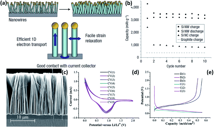 |
| | Fig. 1 (a) Schematic of Si NWs grown directly on the current collector. (b) Capacity versus cycle number for the Si NWs at a rate of C/20. Reprinted with permission from ref. 30. Copyright 2008 Nature Publishing Group. (c) Typical cross-sectional SEM image of Si NW arrays prepared by MCEE. (d) Typical cyclic voltammograms (CVs) of the MCEE Si NWs. (e) Charge–discharge profiles of the MCEE Si NWs. Reprinted with permission from ref. 31. Copyright 2008 American Institute of Physics. | |
Nanorods (NRs).
The application of Si NRs in LIB anodes has received extensive consideration.40–45 For example, Si thin films were prepared on Cu foil substrates by CVD and modified by MCEE for the fabrication of Si NRs.40,41 The Si NRs showed considerably better electrochemical performance than the pristine Si thin film. Moreover, Si NRs prepared by oblique-angle deposition (OAD) on Cu foils delivered a high initial reversible capacity of approximately 1500 mA h g−1, and good capacity retention was achieved for 25 charge–discharge cycles.42 The good electrochemical performance of these Si NRs is attributed to the nanostructure, which provides free vacancies to contain the volume variation and absorb the stress caused by the Li intercalation. However, special devices, harsh reaction conditions and multi-step procedures are usually involved in the above-mentioned synthesis methods for Si NRs. In 2007, Bao et al.46 reported the fabrication of microporous Si by reducing microporous silica via a magnesiothermic reduction process. Using the same method, Si NRs composed of small nanocrystals were successfully prepared by reducing SiO2 nanotubes.43 In addition to the eco-friendly and facile synthesis route, these Si NRs displayed significantly improved electrochemical performance compared to the bulk silicon and porous silicon networks. Discharged/charged at a current density of 0.2 A g−1 for 170 cycles, a reversible capacity of approximately 1038 mA h g−1 was still maintained.
Nanosheets (NSs).
NSs are also of great interest in LIB anodes due to their low dimensional features. First, the ultrathin Si NSs permit the fast kinetics of charge carriers and Li+ diffusion. Second, the nanosheet structures may effectively buffer the strain generated during the lithiation/delithiation processes. Third, the large specific surface area allows effective contact between the electrolyte and the electrode, contributing to the high specific capacities. For instance, Lu et al.47 reported the preparation of ultrathin Si NSs by using graphene oxide (GO) as the template. These Si NSs retained a discharge capacity of approximately 600 mA h g−1 with a coulombic efficiency of 96.2% after discharge/charge at a current density of 0.1C for 100 cycles, demonstrating their good lithium storage properties. However, the fabrication of these Si NSs is quite complicated and the yield is very low. Recently, ultrathin Si NSs have been prepared by a scalable DC arc-discharge plasma method.48 The thickness of the Si NSs was less than 2.5 nm and the average size was about 20 nm. The NSs exhibited superior cycling stability and high rate capability.
2.2 Hollow Si nanostructures
Nanotubes (NTs).
Si NTs are regarded as promising anode materials for LIBs. The axial tubes provide accessible channels for electrolyte transportation and additional space for volume expansion during cycling. Furthermore, both inner and outer walls of NTs are exposed to the electrolyte, shortening the lithium diffusion length. Park et al.49 fabricated Si NTs by the reductive decomposition of a Si precursor in a porous Al template. At a rate of 1C, these NTs showed high reversible charge capacities of approximately 3200 mA h g−1 with excellent capacity retention of 89% after 200 cycles. Yoo et al.50 prepared Si NTs using electrospun polyacrylonitrile nanowires as templates. The electrochemical performance of the Si NTs was proved to be much better than those of commercial Si nanoparticles and Si NWs. At a current density of 0.4 mA g−1, an initial discharge capacity of approximately 1900 mA h g−1 was achieved and good capacity retention was also demonstrated. It is supposed that the pulverization issue can be addressed by introducing the above-mentioned nanotubular structures. However, the formation of the unstable SEI is still quite serious. Wu et al.51 recently proposed novel double-walled Si–SiOx nanotubes (DWSi NTs) to prevent the formation of the unstable SEI. Continuous Si NTs with an oxide coating layer on the outer surface were prepared by using an electrospun nanofiber templating method (schematically illustrated in Fig. 2a). The DWSi NTs showed much better electrochemical performance than Si NTs without oxide and Si NWs. In addition, high specific charge capacities (∼2970 mA h g−1 at C/5, 1000 mA h g−1 at 12C), long cycle life (6000 cycles with 88% capacity retention at 12C), and high rate capability (up to 20C) have been realized in the DWSi NTs. These highly desirable electrochemical parameters are attributed to the unique structure of these DWSi NTs. The outside SiOx coating layer is mechanically rigid and can prevent Si from expanding outward while still permitting Li+ to pass through. Furthermore, the electrolyte does not wet inside the NTs due to the high aspect ratio of the continuous NTs. Thus, the outer surface of the NTs interfaced with the electrolyte is static, allowing for the generation of a stable SEI on the outer surface. The formation of the stable SEI is confirmed by the SEM image of NTs after 2000 cycles and impedance measurements for NTs after different number of cycles (Fig. 2b and c).
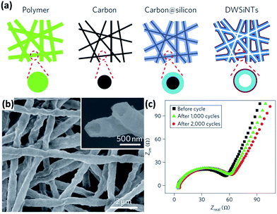 |
| | Fig. 2 (a) Schematic of the preparation process for DWSi NTs. (b) SEM image of DWSi NTs after 2000 cycles, showing the NTs coated with a uniform thin SEI layer. (c) Impedance measurements for DWSi NTs after different number of cycles, indicating no significant growth of SEI during cycling. Reprinted with permission from ref. 51. Copyright 2012 Nature Publishing Group. | |
Hollow spheres (HSs).
Si HSs have a large inner void space, which can well accommodate the volume expansion and relieve the diffusion-induced stress during cycling. In addition, the thin shell of Si HSs can significantly shorten the diffusion distance for the Li+ and electrolyte. Yao et al.52 reported interconnected Si HSs prepared by the CVD method by using SiO2 spheres as hard templates (Fig. 3a). The Si HSs with an inner radius of approximately 175 nm and an outer radius of about 200 nm (Fig. 3b and c) show excellent electrochemical performance. An initial reversible capacity of as high as 2725 mA h g−1 was achieved at a rate of 0.1C and a discharge capacity of 1420 mA h g−1 was obtained at 0.5C for 700 cycles. Unfortunately, the whole CVD process, which involves toxic SiH4 and SiO2 spheres, is not feasible for mass production. Chen et al.53 reported a scalable and simple method for the preparation of uniform Si HSs through the magnesiothermic reduction of mesoporous silica HSs (Fig. 3d). The Si HSs have an average diameter and shell thickness of approximately 120 and 20 nm, respectively (Fig. 3e and f). The Si HSs displayed improved electrochemical performance compared to commercial Si nanoparticles.
 |
| | Fig. 3 (a) Schematic illustration of the preparation of Si HSs. (b and c) SEM and TEM images of Si HSs prepared by a CVD method. Reprinted with permission from ref. 52. Copyright 2011 American Chemical Society. (d) Schematic diagram of the procedure to prepare Si HSs. (e and f) SEM and TEM images of Si HSs prepared by a magnesiothermic reduction method. Reprinted with permission from ref. 53. Copyright 2012 WILEY-VCH Verlag GmbH & Co. KGaA, Weinheim. | |
2.3 Porous Si structures
The introduction of a porous structure to the Si anode has been proven to be a highly efficient strategy to improve the electrochemical performance of Si materials.54–68 The pores of these Si materials can effectively buffer the large volume expansion upon lithiation, contributing to better cycling performance. In addition, the porous structure can facilitate the transport of Li+ and electrolyte, benefiting the rate performance. Roughly, there are two types of methods for the fabrication of porous Si materials, the non-template approach and template-assisted approach.69
Non-template approach.
Electroless etching via a galvanic displacement between Si and metal particles is an effective way to produce porous Si. For example, Ge et al.54 fabricated porous Si nanoparticles by a two-step approach combining boron doping and Ag-assisted chemical etching (Fig. 4a). The porosity of these porous Si nanoparticles can be controlled by adjusting the ratio of Si and boric acid during the doping procedure (Fig. 4b–d). Bang et al.55 reported the preparation of porous Si by a similar etching method (Fig. 4e). The Si had a three-dimensional (3D) porous structure with a pore size of hundreds of nanometres, and an average particle size of approximately 7 μm (Fig. 4f–h). Ge et al.56 prepared porous Si particles from bulk metallurgical Si by a two-step approach combining ball milling and Fe-assisted chemical etching (Fig. 4i). The pores with a size of around 3 nm were uniformly distributed over the surface of bulk Si (Fig. 4j and k). The electrochemical performance of the porous Si was much superior to that of the non-porous bulk Si substrate.
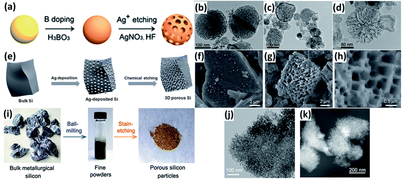 |
| | Fig. 4 (a) Schematic illustration of the preparation of porous Si nanoparticles. TEM images of porous Si nanoparticles prepared with initial H3BO3![[thin space (1/6-em)]](https://www.rsc.org/images/entities/char_2009.gif) : :![[thin space (1/6-em)]](https://www.rsc.org/images/entities/char_2009.gif) Si mass ratios of 2 Si mass ratios of 2![[thin space (1/6-em)]](https://www.rsc.org/images/entities/char_2009.gif) : :![[thin space (1/6-em)]](https://www.rsc.org/images/entities/char_2009.gif) 5 (b), 4 5 (b), 4![[thin space (1/6-em)]](https://www.rsc.org/images/entities/char_2009.gif) : :![[thin space (1/6-em)]](https://www.rsc.org/images/entities/char_2009.gif) 5 (c), and 8 5 (c), and 8![[thin space (1/6-em)]](https://www.rsc.org/images/entities/char_2009.gif) : :![[thin space (1/6-em)]](https://www.rsc.org/images/entities/char_2009.gif) 5 (d), respectively. Reprinted with permission from ref. 54. Copyright 2013 Springer. (e) Schematic diagram of the procedure to prepare porous bulk Si. (f) SEM image of Ag-deposited Si. (g and h) SEM images of chemically etched Si. Reprinted with permission from ref. 55. Copyright 2012 WILEY-VCH Verlag GmbH & Co. KGaA, Weinheim. (i) Synthesis route of porous Si from metallurgical Si by a two-step approach combining ball milling and Fe-assisted chemical etching. (j) TEM image of porous Si particles. (K) STEM image of porous particles. Reprinted with permission from ref. 56. Copyright 2013 American Chemical Society. 5 (d), respectively. Reprinted with permission from ref. 54. Copyright 2013 Springer. (e) Schematic diagram of the procedure to prepare porous bulk Si. (f) SEM image of Ag-deposited Si. (g and h) SEM images of chemically etched Si. Reprinted with permission from ref. 55. Copyright 2012 WILEY-VCH Verlag GmbH & Co. KGaA, Weinheim. (i) Synthesis route of porous Si from metallurgical Si by a two-step approach combining ball milling and Fe-assisted chemical etching. (j) TEM image of porous Si particles. (K) STEM image of porous particles. Reprinted with permission from ref. 56. Copyright 2013 American Chemical Society. | |
Template-assisted approach.
Monodispersed SiO2 nanospheres with a tunable particle size are widely used as sacrificial hard templates to form porous Si structures. For example, Esmanski et al.57 reported a porous Si prepared by CVD with SiO2 hard templates. Typically, monodispersed SiO2 spheres with a diameter of 890 nm were first prepared by a modified Stöber method, and then deposited onto a substrate via an evaporation-induced self-assembly method. Hydrogenated amorphous Si was then deposited in the interstices of SiO2 spheres by dynamic cold-wall low-pressure CVD by using Si2H6 as a Si source. The porous Si was finally obtained by dissolving SiO2 in HF solution (Fig. 5a and b). In another example, a SiO2 sphere template was mixed with Si gel formed by reducing SiCl4 with sodium naphthalide and annealed at elevated temperature. A porous Si material was obtained after HF treatment (Fig. 5c and d).58 This Si material with a 3D interconnected porous structure had good capacity retention of 90% up to 100 cycles at a rate of 1C.
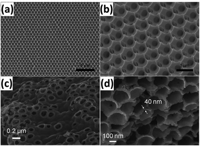 |
| | Fig. 5 (a and b) SEM images of porous Si templated from 890 nm pre-sintered SiO2 spheres. Reprinted with permission from ref. 57. Copyright 2009 WILEY-VCH Verlag GmbH & Co. KGaA, Weinheim. (c and d) SEM images of 3D porous Si prepared by reduction of SiCl4 with a SiO2 template. Reprinted with permission from ref. 58. Copyright 2008 WILEY-VCH Verlag GmbH & Co. KGaA, Weinheim. | |
In addition to the sacrificial template method, self-templating is also an efficient approach to generate porous Si structures. Mesoporous SiO2 materials can serve as both templates and silicon sources. Many porous Si materials have been generated through the magnesiothermic reduction of mesoporous SiO2. Typically, SiO2 powder is mixed with magnesium powder and then heated in a tube furnace. When the temperature reaches 650 °C, molten magnesium is imbibed into the pores and reacts with SiO2 to form a MgO–Si nanocomposite. Porous Si materials are acquired by the removal of MgO and residual SiO2 by an acid. For instance, Yu et al.59 reported the preparation of porous Si via reduction of mesoporous SiO2 with a pore diameter of approximately 10 nm. The obtained Si particles have a coherent macroscopic porous network with pores of about 200 nm diameter and wall thickness ranging from 150 to 250 nm (Fig. 6a and b). Since then, highly ordered mesoporous SiO2 materials, such as SBA-1560 and KIT-6,61 were also used as precursors to prepare porous Si by this magnesiothermic reduction method. The Si particles with the original morphology of mesoporous SiO2 have porous structures composed of homogeneously distributed primary Si crystallites with the size of 20–30 nm (Fig. 6c–f). Moreover, the high specific surface areas of these porous Si particles are favourable for the fast electrode kinetics. More recently, natural reservoirs with high contents of SiO2 and large number of pores, such as rice husk62–64 and diatomite,65,66 have also been used as raw materials for the preparation of porous Si. As revealed by the charge/discharge test, the porous Si showed much better electrochemical performance than commercial Si nanoparticles due to the presence of the porous structures. Table 1 summarizes the most recent electrochemical data on Si nanostructures for LIB anodes reported in the literature.
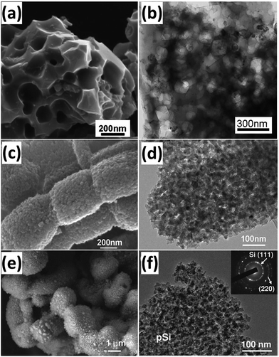 |
| | Fig. 6 (a and b) SEM and TEM images of porous Si templated from mesoporous SiO2 powder. Reprinted with permission from ref. 59. Copyright 2010 WILEY-VCH Verlag GmbH & Co. KGaA, Weinheim. (c and d) SEM and TEM images of porous Si templated from SBA-15. Reprinted with permission from ref. 60. Copyright 2011 WILEY-VCH Verlag GmbH & Co. KGaA, Weinheim. (e and f) SEM and TEM images of porous Si templated from KIT-6. Reprinted with permission from ref. 61. Copyright 2011 Royal Society of Chemistry. | |
Table 1 Synthesis strategies and electrochemical properties of Si nanostructure anode materials in LIBs
| Sample |
Methods |
Initial reversible capacity (mA h g−1) |
Initial coulombic efficiency (%) |
Capacity (mA h g−1) |
References |
| Si thin films |
Electrodepositing |
2550 at 0.36 A g−1 |
53 |
2800 after 80 cycles |
23
|
| Si thin films |
PECVD |
2875 at 1C |
50 |
2100 after 100 cycles |
25
|
| Si thin films |
Magnetron sputtering |
3134 at 0.025C |
87 |
1317 at 0.5C after 500 cycles |
27
|
| Si NWs |
VLS-CVD |
3124 at 0.05C |
73 |
3250 after 10 cycles |
30
|
| Si NWs |
HF-CVD |
3720 at 0.1C |
65 |
2670 at 1.3C after 50 cycles |
34
|
| Si NWs |
CVD |
1640 at 0.2C |
79 |
1300 after 100 cycles |
35
|
| Si NWs |
VLS-CVD |
2836 at 0.1C |
93.7 |
2600 after 20 cycles |
38
|
| Si NWs |
PECVD |
3500 at 0.05C |
96 |
2930 at 0.5C after 50 cycles |
39
|
| Si NRs |
ECR-CVD/MCEE |
2911 at 0.25 mA cm−2 |
95 |
2445 after 25 cycles |
40
|
| Si NRs |
ECR-MOCVD/MCEE |
2990 at 0.15C |
92 |
1420 after 100 cycles |
41
|
| Si NRs |
Magnesiothermic reduction |
1586 at 0.2 A g−1 |
48.3 |
1038 after 170 cycles |
43
|
| Si NRs |
RF-PECVD/DRIE |
2348 at 1.2C |
60 |
1244 after 25 cycles |
45
|
| Si NSs |
Magnesiothermic reduction |
— |
— |
600 at 0.1C after 100 cycles |
47
|
| Si NSs |
DC arc-discharge plasma |
1242 at 0.1 A g−1 |
49 |
442 after 40 cycles |
48
|
| Si NTs |
Electrospinning/CVD |
650 at 12C |
76 |
570 after 6000 cycles |
51
|
| Si HSs |
CVD |
2725 at 0.1C |
77 |
1420 at 0.5C after 700 cycles |
52
|
| Si HSs |
Magnesiothermic reduction |
— |
— |
1750 at 0.5 A g−1 after 50 cycles |
53
|
| Porous Si |
MCEE of Si powders |
1780 at 0.1C |
69.3 |
125 after 30 cycles |
55
|
| Porous Si |
MCEE of bulk metallurgical Si |
— |
— |
>1400 at 0.2C after 160 cycles |
56
|
| Porous Si |
CVD with SiO2 hard templates |
2698 at 0.1C |
87.2 |
2000 after 145 cycles |
57
|
| Porous Si |
Magnesiothermic reduction of mesoporous SiO2 |
2416 at 0.1 A g−1 |
73.7 |
1600 after 100 cycles |
59
|
| Porous Si |
Magnesiothermic reduction of rice husk |
2790 at 84 mA g−1 |
70 |
1500 at 2.1 A g−1 after 300 cycles |
63
|
| Porous Si |
Magnesiothermic reduction of diatomite |
1826 at 50 mA g−1 |
68.5 |
240 after 30 cycles |
65
|
3. Formation of Si composites
Introducing hollow and porous structures has been proved to be efficient in addressing the issues of Si electrodes, such as volume expansion upon lithiation, diffusion distance of lithium ions, and diffusion-induced stress. However, due to the high porosity and specific surface area, these structures usually have very low tap densities and consequently result in low volumetric energy density. Given this fact, Si NPs with high tap densities are regarded as practically applicable anode materials for LIBs. In addition, Si NPs are commercially available and compatible with the current slurry coating manufacturing process for LIB electrodes. However, unlike other Si nanostructures described in Section 2, Si NPs are prone to pulverization during cycling, leading to rapid capacity loss. Thus, Si NPs cannot be directly used for a LIB electrode. To address these issues, many conductive agents, such as carbonaceous materials, metals, and polymers, have been incorporated into Si NPs.
3.1 Incorporation of carbonaceous materials
Carbon coatings.
The formation of carbon coatings has been widely exploited and considered as an efficient method to enhance the electrochemical performance of Si NPs. The carbon coating improves the electric conductivity and restricts the volume change of Si upon cycling. In addition, such coating also allows for the formation of a stable SEI upon cycling and prevents the deterioration of the electrode performance. Various methods, such as CVD by using toluene or propylene gas70–72 and pyrolysis of carbonaceous precursors,73–90 have been employed to fabricate carbon coatings on the surface of Si NPs. Magasinski et al.70 prepared Si NPs/carbon composite granules through hierarchical bottom-up assembly. As illustrated in Fig. 7a, carbon-black nanoparticles were branched into short chains by high-temperature pre-annealing. Si NPs were then deposited onto the annealed carbon-black by a CVD method employing SiH4 as a Si source. The multibranched nanocomposite was finally self-assembled into large porous spherical granules during the following carbon deposition. The produced spheres have particle sizes ranging from 15 to 30 μm (Fig. 7b and c) and pore sizes of 30–100 nm in diameter (Fig. 7d and e). The incorporation of carbon and the presence of the porous structure endow the Si NPs/carbon composite granules with high electrochemical performance. A high reversible capacity of 1950 mA h g−1 is achieved at C/20 and a capacity close to 82% of this maximum is maintained at 1C over 100 cycles (Fig. 7f). Recently, yolk–shell structures have been widely investigated for further improving the performance of Si NPs/carbon composites. Liu et al.73 reported the preparation of a pomegranate-like Si NPs/C composite by a polymer-pyrolysis method. As illustrated in Fig. 7g, commercial Si NPs coated with a SiO2 layer were mixed with an emulsifier to form water-in-oil emulsions. A resorcinol-formaldehyde (RF) resin layer was generated on the surface of assembled Si@SiO2 nanoparticle clusters, and then converted into a carbon coating by a carbonization process. After the removal of SiO2 with HF solution, a pomegranate-like Si NPs/C composite with plenty of void space between the Si NPs and carbon coating was generated (Fig. 7h–j). Due to the carbon coating and yolk–shell structure, the composite showed much better electrochemical performance than raw Si and Si cluster@C (Fig. 7k). A reversible capacity of 2350 mA h g−1 was achieved at a rate of C/20. From the second to 1000th cycle at a rate of C/2, the capacity retention was more than 97%. Su et al.89 also fabricated yolk–shell Si@void@C nanocomposites via a facile RF coating and subsequent LiOH etching. The nanocomposites showed much better electrochemical behaviors than raw Si and Si@C.
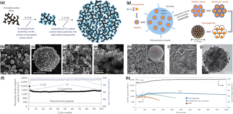 |
| | Fig. 7 (a) Schematic of Si NPs/carbon composite granules formation via hierarchical bottom-up assembly. (b–e) SEM images of the Si NPs/carbon composite granules recorded at different magnifications. (f) Coulombic efficiency and reversible Li deintercalation capacity of the Si NPs/carbon composite granules versus cycle number. Reprinted with permission from ref. 70. Copyright 2010 Nature Publishing Group. (g) Schematic of the fabrication process for silicon pomegranates. (h and i) SEM images of the Si pomegranates recorded at different magnifications. (j) TEM image of one Si pomegranate particle. (k) Cycling performance of Si pomegranates, Si cluster@C, and Si NPs under the same conditions. Coulombic efficiency is plotted for the Si pomegranates only. Reprinted with permission from ref. 73. Copyright 2014 Nature Publishing Group. | |
Carbon nanofibers.
Encapsulation into carbon nanofibers (CNFs) has also been regarded as an efficient approach to improve the electrochemical performance of Si NPs.91–101 Electrospinning is the most common way to prepare Si NPs/CNFs composites. Hwang et al.91 developed an electrospinning process to produce a Si NPs/CNFs composite using a dual nozzle (Fig. 8a). Si NPs and poly(methyl methacrylate) in N,N-dimethylformamide (DMF) and acetone were injected into the core channel of the nozzle. Polyacrylonitrile (PAN) dissolved in DMF was injected into the shell channel of the nozzle. After carbonization following the electrospinning process, the Si NPs/CNFs composite with a diameter of about 1 μm was generated (Fig. 8b and c). The Si NPs were completely wrapped by a carbon shell, forming a core–shell structure (Fig. 8d and e). The carbon shell not only alleviates the large volume expansion of Si NPs but also promotes the electronic transportation of the electrode through the formation of a conductive network. In addition, the carbon shell can reduce the surface contact of NPs with the electrolyte and prevent the pulverization of Si NPs during cycling. The Si NPs/CNFs composite exhibited excellent cycling and rate performance. Cycled at a rate of 3C, only 1% of the initial capacity was lost after 300 cycles (Fig. 8f). Increasing the rate from C/10 to 12C, 52.2% of the original capacity was still maintained (Fig. 8g).
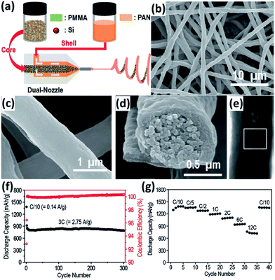 |
| | Fig. 8 (a) Schematic illustration of the electrospinning process. SEM images of the Si NPs/CNFs composite at (b) low and (c) high magnifications. (d) A cross-sectional SEM view of a single Si NPs/CNF. (e) A TEM image of a single Si NPs/CNF. (f) Cycling performance of the Si NPs/CNFs composite measured at a 3C rate (2.748 A g−1). (g) Rate capability test for the Si NPs/CNFs composite. Reprinted with permission from ref. 91. Copyright 2011 American Chemical Society. | |
Carbon nanotubes.
Carbon nanotubes (CNTs) with properties of high electric conductivity, large accessible surface area, good mechanical properties, and chemical stability are a promising electrode material. The incorporation of CNTs can improve the electric conductivity of an electrode and prevent the aggregation of Si during cycling, leading to improved performance for the Si NPs/CNTs composites.102–113 For example, Wang et al.102 prepared a Si NPs/CNTs composite by a simple two-step CVD. As illustrated in Fig. 9a, the CNTs with an average diameter of 40–50 nm were first grown on quartz slides in a liquid injection based CVD reactor with xylene as the carbon source and ferrocene as the catalyst. Si NPs were then deposited onto CNTs by using SiH4 as a Si source (Fig. 9b and c). The Si NPs/CNTs composite maintained a capacity of over 2000 mA h g−1 at a current density of 100 mA g−1 after 25 cycles (Fig. 9d). Increasing the current rate to 2.5C, a capacity of approximately 1000 mA h g−1 was achieved, demonstrating high rate capability (Fig. 9e). Si NPs/CNTs composites can also be prepared by mixing pretreated Si NPs and aminophenyl-grafted CNTs in acetonitrile and the subsequent addition of tert-butylnitrite, resulting in the close binding of Si NPs and CNTs (Fig. 9f and g).103 After grafting with CNTs, a capacity of 1000 mA h g−1 was achieved for these Si NPs at a current density of 0.5 A g−1 after 35 cycles (Fig. 9h).
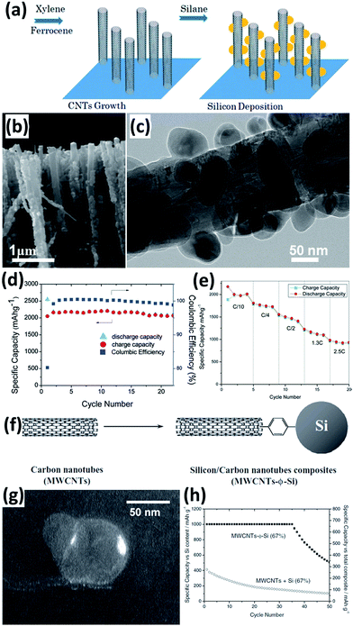 |
| | Fig. 9 (a) Schematic diagram showing the preparation of the Si NPs/CNTs composite. (b) SEM image of the Si NPs/CNTs composite. (c) TEM image of a single Si NPs/CNT. (d) Cycling performance of the Si NPs/CNTs composite at a current density of 100 mA g−1. (e) Rate capability of the Si NPs/CNTs composite. Reprinted with permission from ref. 102. Copyright 2010 American Chemical Society. (f) Preparation of Si NPs/CNTs composite via a phenyl bridge. (g) Dark-field image of Si NPs showing that the particles are not only attached to the edge of CNTs but also by the walls. (h) Cycling performance of the Si NPs/CNTs composite at a current density of 0.5 A g−1. Reprinted with permission from ref. 103. Copyright 2011 WILEY-VCH Verlag GmbH & Co. KGaA, Weinheim. | |
Graphene nanosheets.
Graphene (G) itself shows a low reversible capacity as an insertion host of LIBs. If used as a conducting and buffering matrix, G can greatly improve the electrochemical performance of Si NPs.114–134 G can reduce the surface contact of NPs with the electrolyte and improve the electric conductivity of the electrode. Furthermore, the void space between the Si NPs and G can accommodate the volume variation during cycling, maintaining the integrity of the electrode. Researchers have developed several approaches to fabricate Si NPs/G composites for LIBs. For instance, Chabot et al.114 reported the preparation of a Si NPs/G composite by simply combining freeze-drying and thermal reduction processes (Fig. 10a). Si NPs were mixed with GO aqueous dispersion and sonicated for five hours. After lyophilization and subsequent treatment in a tube furnace at 700 °C for 3 h under an Ar atmosphere containing 10 vol% H2, the Si NPs/G composite was obtained. SEM image shows that well-distributed Si NPs are wrapped by G (Fig. 10b). The composite achieved an initial discharge capacity of 2312 mA h g−1 with 78.7% capacity retention after 100 cycles. A Si NPs/G composite has also been fabricated through an in situ pyrolysis and metal-catalyzed graphitization reaction (Fig. 10c).115 Si NPs were first coated by an Ag sacrificial layer via a modified silver mirror reaction. The uniformly mixed Si@Ag composite, glucose and FeSO4 were transferred into a tube furnace and heated up to 750 °C for 6 h under an Ar/H2 atmosphere. After etching away the Ag layer in acid, the Si NPs/G composite was obtained. Voids ranging from 35 to 43 nm between the Si NP core and G shell are clearly observed (Fig. 10d). A high capacity of 1410 mA h g−1 was retained even after 600 cycles, indicating high cycling stability of this composite.
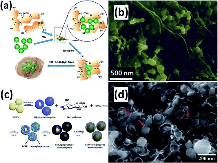 |
| | Fig. 10 (a) Schematic view for preparation of the Si NPs/G composite. (b) SEM image of the Si NPs/G composite. Reprinted with permission from ref. 114. Copyright 2014 Elsevier. (c) Schematic diagram of the synthesis process of the Si NPs/G composite. (d) SEM image of the Si NPs/G composite. Reprinted with permission from ref. 115. Copyright 2015 Royal Society of Chemistry. | |
3.2 Incorporation of metal nanoparticles
Surface modification by metal nanoparticles such as Cu and Ag has been frequently adopted to improve the electrochemical performance, particularly coulombic efficiency and rate capability of Si NPs.135–138 The metal nanoparticle coating layers can enhance the surface electrical conductivity of Si, offering electron percolation paths from the current collector to the whole surface area of each individual Si nanoparticle. These coating layers can also prevent the aggregation of Si NPs and reduce the surface contact of NPs with the electrolyte, forming a stable SEI layer. Employing butylamine as a reducing agent and AgNO3 as an Ag precursor, Ag nanoparticles with an average diameter of 13 nm are uniformly anchored on the surface of Si NPs (Fig. 11a and b).135 Due to the modification of Ag nanoparticles, the electrochemical properties of the Si NPs/Ag composite are much superior to that of the Si NPs alone. The initial coulombic efficiency increased from 76.9% to 80%. A charge capacity of 1320 mA g h−1 was still maintained at a rate of 0.2C for 100 cycles, corresponding to nearly 100% capacity retention against that the second cycle (Fig. 11c). The composite also showed high rate capability. At a high rate of 5C, capacity retention of 46.4% could be achieved (Fig. 11d).
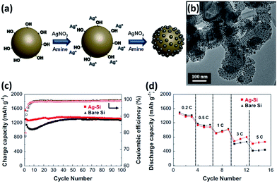 |
| | Fig. 11 (a) Schematic illustration showing the preparation of the Si NPs/Ag composite. (b) TEM image of the Si NP s/Ag composite. (c) Cycling performance and (d) rate capability (0.2–10C rates) of bare Si and Si NPs/Ag composite. Reprinted with permission from ref. 135. Copyright 2014 Elsevier. | |
3.3 Conductive polymers
Conductive polymers have many attractive features, including good electrical conductivity, high structural flexibility and superior chemical stability. Conductive polymers, such as polypyrrole (PPy) and polyaniline (PANi) have been widely employed to improve the electrochemical performance of Si NPs.139–147 In 2005, PPy was incorporated into Si NPs via a high-energy mechanical milling process by Guo et al.139 The obtained Si NPs/PPy composite showed enhanced electrochemical performance. However, it is hard to form uniform PPy coating on the surface of Si NPs by simple mechanical milling, impacting on the formation of a continuous electronic transport pathway. Recently, Wu et al.140 reported the incorporation of PANi hydrogel into Si NPs by an in situ chemical polymerization technique. The Si NPs encapsulated by a conformal PANi layer are well distributed inside the highly porous PANi matrix (Fig. 12a–c). Moreover, the obtained Si NPs/PANi gel could be directly bladed onto a current collector without using any binder and conducting particles. A capacity of approximately 550 mA h g−1 was achieved at a current density of as high as 6.0 A g−1 for 5000 cycles, corresponding to 91% capacity retention (Fig. 12d). In addition, the capacity varied from 2500 to 1100 mA h−1 at a charge/discharge rate from 0.3 to 3.0 A g−1, demonstrating excellent rate capability (Fig. 12e). The exceptional electrochemical performance of the Si NPs/PANi composite is attributed to its unique structure. First, the porous hydrogel matrix has empty space to allow for the huge volume expansion of the Si NPs during cycling. Second, the incorporation of PANi prevents the aggregation of Si NPs and reduces the surface contact of Si NPs with the electrolyte, facilitating the formation of a stable SEI layer. Third, the conformal PANi coating surrounding each Si NP, as well as the conductive and continuous 3D framework, helps provide good electrical connection to the nanoparticles.
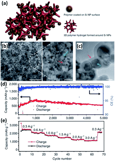 |
| | Fig. 12 (a) Schematic illustration of the 3D porous Si NP/PANi hydrogel composite. (b) SEM image of the Si NPs/PANi composite at low (left) and high (right) magnification. Scale bar, 1 μm (left) and 200 nm (right). (c) TEM image of the Si NPs/PANi composite. Scale bar, 50 nm. (d) Cycling performance of the Si NPs/PANi composite at a current density of 6.0 A g−1 for 5000 cycles. (e) Rate capability of the Si NPs/PANi composite. Reprinted with permission from ref. 140. Copyright 2013 Nature Publishing Group. | |
Table 2 presents a summary of the synthesis strategies and electrochemical characteristics of Si NPs-based composites reported in the literature recently. As described in Section 3 and listed in Table 2, the incorporation of conductive materials can effectively improve the electrochemical performance of Si NPs. It is interesting to combine the nanostructures such as solid nanostructures, hollow nanostructures and porous structures described in Section 2 with conductive material modification to enhance the performance of Si anodes.148 For instance, Zhang et al.149 prepared SiOx microparticles with homogeneously-embedded Si nanocrystals and nanopores via magnesiothermic reduction of SiO2. The SiOx microparticles were further modified by a PANi–Ag shell through in situ polymerization. The obtained composite exhibited excellent cycling performance with a reversible capacity of 1149 mA h g−1 after 100 cycles. The enhanced performance is mainly attributed to the combination of the porous structure and high-electronic-conductivity PANi–Ag layers. Recently, porous Si was prepared in our group via the magnesiothermic reduction of MCM-41, followed by dual surface modification of Ag NPs and G.150 The obtained composite showed a distinctly high reversible capacity, good cycling stability and super rate capability. An initial discharge capacity as high as 3531 mA h g−1 was achieved at 0.1 A g−1. A capacity of 1241 mA h g−1 was still retained at a high current density of 32 A g−1 for 50 cycles. The exceptional electrochemical performance of the composite is attributed to a synergistic effect, stemming from the combination of the porous Si structure and dual surface modification. More recently, uniform porous Si hollow nanospheres (PHSi) were fabricated by our group through the magnesiothermic reduction of mesoporous SiO2 hollow nanospheres (MHSiO2). These hollow nanospheres were surface modified by subsequent in situ chemical polymerization of PPy.151 The as-prepared PPy@PHSi nanocomposite delivered a high initial discharge capacity of 2603 mA h g−1 and showed an excellent cycling stability with 88% capacity retention against that at the 2nd cycle after 250 cycles. SEM and TEM observations showed that the spherical morphology and hollow structure of the nanocomposite are well maintained after cycling for 250 cycles (Fig. 13). Although volume expansion from 700 to over 900 nm is observed, no distinct fractures of Si and exfoliation of PPy coating are detected, indicating the high structural stability of the nanocomposite. The combination of the porous hollow Si structure and PPy coating can synergistically improve the electrochemical performance of the nanocomposite.
Table 2 Synthesis strategies and electrochemical characteristics of Si NPs-based composites in LIBs
| Sample |
Methods |
Si content (wt%) |
Initial reversible capacity (mA h g−1) |
Initial coulombic efficiency (%) |
Capacity (mA h g−1) |
References |
| Si NPs/C |
CVD |
70.4 |
1850 at 0.1 A g−1 |
80.1 |
1600 at 0.3 A g−1 after 70 cycles |
71
|
| Si NPs/C |
CVD |
37 |
783 at 0.1 A g−1 |
57.1 |
767 after 100 cycles |
72
|
| Si NPs/C |
Pyrolysis |
77 |
2350 at C/20 |
75 |
1160 at 0.5C after 1000 cycles |
73
|
| Si NPs/C |
Pyrolysis |
42 |
902 at 0.1 A g−1 |
57 |
678 at 0.1 A g−1 after 50 cycles |
74
|
| Si NPs/C |
Pyrolysis |
58.9 |
759 at 0.1 A g−1 |
41 |
1000 after 100 cycles |
78
|
| Si NPs/C |
Pyrolysis |
71 |
2833 at 0.1C |
60 |
1110 at 1C after 1000 cycles |
88
|
| Si NPs/CNFs |
Electrospinning |
50 |
1305 at 0.1C |
87.5 |
750 at 3C after 300 cycles |
91
|
| Si NPs/CNFs |
Electrospinning |
50.2 |
1598 at 0.5 A g−1 |
60.5 |
1104 after 100 cycles |
92
|
| Si NPs/CNFs |
Electrospinning |
26.3 |
962 at 0.05 A g−1 |
77.1 |
647 after 50 cycles |
100
|
| Si NPs/CNFs |
Electrospinning |
— |
886 at 0.05 A g−1 |
76.3 |
452 after 50 cycles |
101
|
| Si NPs/CNFs |
CVD |
32 |
1448 at 0.1 A g−1 |
71 |
1042 after 20 cycles |
96
|
| Si NPs/CNTs |
CVD |
— |
2049 at 0.1 A g−1 |
80.3 |
2000 after 25 cycles |
102
|
| Si NPs/CNTs |
CVD |
59.6 |
860 at 0.05C |
63 |
602 after 140 cycles |
113
|
| Si NPs/CNTs |
Ball milling |
50 |
1601 at 0.2 A g−1 |
66 |
757 after 30 cycles |
110
|
| Si NPs/G |
Metal-catalyzed graphitization |
89.5 |
2411 at 0.05C |
65 |
1410 at 0.5C after 600 cycles |
115
|
| Si NPs/G |
Aerosol spraying |
72 |
1800 at 1C |
60 |
1500 after 120 cycles |
117
|
| Si NPs/G |
Thermal reduction |
45 |
1143 at 0.3 A g−1 |
63 |
800 after 30 cycles |
119
|
| Si NPs/G |
Spray drying/thermal reduction |
80.9 |
1525 at 0.1 A g−1 |
70 |
1500 at 0.2 A g−1 after 30 cycles |
120
|
| Si NPs/G |
Freeze drying/thermal reduction |
82.1 |
1866 at 0.2 A g−1 |
60.8 |
1153 after 100 cycles |
122
|
| Si NPs/G |
Microwave drying/thermal reduction |
31 |
984 at 0.5 A g−1 |
61 |
815 after 100 cycles |
124
|
| Si NPs/G |
Freeze drying/thermal reduction |
65 |
1218 at 0.1 A g−1 |
89.9 |
850 after 100 cycles |
128
|
| Si NPs/G |
Freeze drying/thermal reduction |
91.7 |
1079 at 0.3 A g−1 |
59.9 |
828 after 50 cycles |
131
|
| Si NPs/G |
Freeze drying/thermal reduction |
80 |
2535 at 0.15 A g−1 |
73.6 |
1984 after 40 cycles |
133
|
| Si NPs/G |
Steam etching |
50 |
1536 at 0.05 A g−1 |
48.8 |
1004 after 100 cycles |
125
|
| Si NPs/Ag |
Chemical reduction using butylamine |
97 |
1550 at 0.1C |
80 |
1320 at 0.2C after 100 cycles |
135
|
| Si NPs/Ag |
Mechanical milling |
90 |
2050 at 0.1 mA cm−2 |
83.4 |
800 after 30 cycles |
138
|
| Si NPs/PANi |
In situ polymerization |
75 |
1300 at 1.5 A g−1 |
70 |
550 at 6.0 A g−1 after 5000 cycles |
140
|
| Si NPs/PANi |
In situ polymerization |
87.7 |
2794 at 0.4 A g−1 |
77.6 |
1546 after 50 cycles |
142
|
| Si NPs/PPy |
Mechanical milling |
90 |
1919 at 0.126 A g−1 |
53.4 |
100 after 40 cycles |
143
|
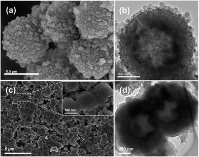 |
| | Fig. 13 (a and b) SEM and TEM images of the PPy@PHSi nanocomposite. (c) SEM image of the PPy@PHSi nanocomposite on a current collector after 250 cycles. (d) TEM image of the PPy@PHSi nanocomposite after 250 cycles. Reprinted with permission from ref. 151. Copyright 2014 WILEY-VCH Verlag GmbH & Co. KGaA, Weinheim. | |
4. Other factors affecting the performance
In addition to the structure, surface and interface impact, other factors such as electrolyte additives, binders, and current collectors also have a significant influence on the capacity and cycle life of Si nanostructures and their composites.
4.1 Electrolyte additives
The SEI generated on the Si surface is usually unstable due to the formation of cracks caused by the large volume expansion of Si during the lithiation process. Fresh Si surfaces exposed would consume the electrolyte constantly, leading to the growth of a thick SEI layer, and ultimately poor electrochemical performance of the electrodes. In order to form a thin and stable SEI layer, chemicals including vinylene carbonate,152–159 tris(pentafluorophenyl)borane,160 succinic anhydride,161,162 and fluoroethylene carbonate (FEC)157–159,163–166 have been added into the electrolytes to improve the performance of Si anodes. Particularly, FEC has been proved to be effective in enhancing the coulombic efficiency and capacity retention of Si anodes. Utilizing an FEC-containing electrolyte (FEC, 10 wt%), only 5% capacity (referring to 1200 mA h g−1) was lost for Si NPs with a particle size of ∼50 nm and coulombic efficiency of approximately 99% was retained after 80 cycles. In contrast, only 70% capacity was preserved without the addition of FEC and the coulombic efficiency dropped to ∼97% after 80 cycles.163 It was also reported that the introduction of FEC into the electrolyte (50 v/v%) increased the discharge capacity of Si thin film from approximately 2750 mA h g−1 to above 3200 mA h g−1, and also enhanced the coulombic efficiency from about 98% to more than 99.5% after 30 cycles.166 The improvement in the electrochemical performance of Si anodes by the FEC additive is well investigated and attributed to the formation of stable FEC-derived SEI film.163,164 The reduction products of FEC mainly consist of –CHF–OCO2 type compounds and LiF. These compounds form an initial SEI which covers the Si surface evenly. This SEI film is mechanically strong enough to prevent the formation of large amounts of cracks, while the LiF contributes the Li+ conductivity in the SEI film. In addition, the initially formed SEI can alleviate the constant decomposition of the electrolyte and thus prevent the continuous generation of a non-uniform SEI layer.
4.2 Binders
Polymers are usually employed to bind conducting particles and active materials together onto the current collector. The properties of binders play a critical role in the LIB performance, especially in the initial coulombic efficiency and cycle stability. Poly(vinylidene fluoride) (PVDF) is commercially used as a binder in the fabrication of LIBs. However, it was found that the weak van der Waals interactions are not sufficient to sustain the electrode integrity during the huge volume change of Si between the fully lithiated and delithiated states.167 Recently, considerable progress has been made in the utilization of functional binders that can enhance the integrity of Si electrodes.167–189 For instance, polymer binders containing carboxyl groups and their derivatives, such as polyacrylic acid (PAA),168 carboxymethyl cellulose (CMC) based polymers,169–171 and alginate (Alg) based polymers,172–175 are employed as binders for Si materials. Compared with PVDF and styrene-butadiene rubber (SBR), these polymer binders show much high binding ability with Si, benefiting from the formation of hydrogen bonding and/or covalent chemical bonds. Recently, Kovalenko et al.172 found that a Si anode fabricated by using alginate as a binder showed better electrochemical performance than that by CMC. As shown in Fig. 14a, the reversible capacity of an Alg-based Si anode is over 1700 mA h g−1 after 100 cycles at a current density of 4200 mA g−1, while that of CMC-based Si is below 1000 mA h g−1 after 40 cycles. In Alg, carboxyl groups are naturally present and evenly distributed in the polymer chain, whereas in CMC they are synthetically induced and their distribution is random. Multi-functional polymer binders have also been developed.176,177 For example, Ryou et al.176 conjugated adhesive catechol functional groups stemming from dopamine hydrochloride to PAA and Alg backbones. As shown in Fig. 14b and c, Si–Alg–C and Si–PAA–C showed better cycling stability than their counterparts without catechol groups. Although the introduction of such functional groups to the polymer chain exhibited higher adhesion associated with better performance of the Si anode, the linear chain nature of these polymer binders is prone to sliding upon the continuous volume variation of Si during cycling. To address this issue, 3D polymer networks, in which the polymer chain was anchored by a cross-linking technique, were sequentially prepared for the Si anodes.173–175,178–183 Koo et al.178 reported a 3D cross-linked polymeric binder prepared by a condensation reaction of PAA and CMC. The c-PAA–CMC binder with Si NPs showed better cycling stability than CMC, PAA and PVDF (Fig. 14d). More recently, self-healing polymers (SHPs) containing abundant hydrogen bonds were used as binders to stabilize Si anodes.184,185 SHPs have both mechanical and electrical healing capabilities, allowing fractures and damages of Si to repeatedly heal during battery cycling. As shown in Fig. 14e, the Si–SHP/carbon black (Si–SHP/CB) electrode with a high mass loading of 1.13 mgsi cm−2 delivered an initial areal capacity of approximately 3.22 mA h cm−2 at a current of 0.1 mA cm−2, and maintained a high areal capacity of 2.72 mA h cm−2 at a current of 0.3 mA cm−2 after about 120 cycles. In comparison, Si electrodes with the same Si and similar mass loadings using CMC or PVDF as the binder exhibited rapid capacity fade after a few cycles.184
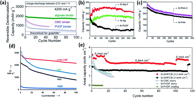 |
| | Fig. 14 (a) The cycling performance of the Si NP electrodes with PVDF, CMC, and Alg binders measured at a current density of 4200 mA g−1. Reprinted with permission from ref. 172. Copyright 2011 American Association for the Advancement of Science. (b and c) The cycling performance of the Si electrodes based on the Alg–C, Alg, PVDF, PAA–C, and PAA binders measured at a current density of 2100 mA g−1. Reprinted with permission from ref. 176. Copyright 2013 WILEY-VCH Verlag GmbH & Co. KGaA, Weinheim. (d) The cycling performance of the Si electrodes employing the c-PAA–CMC, CMC, PAA, and PVDF binders measured at a current density of 300 mA g−1. Reprinted with permission from ref. 178. Copyright 2012 WILEY-VCH Verlag GmbH & Co. KGaA, Weinheim. (e) The cycling performance of the Si–SHP/CB (1.13 mgSi cm−2), Si–SHP/CB (0.72 mgSi cm−2), Si–CMC slurry, Si–PVDF slurry, and Si–PVDF coating electrodes. Reprinted with permission from ref. 184. Copyright 2015 WILEY-VCH Verlag GmbH & Co. KGaA, Weinheim. | |
4.3 Current collectors
Current collectors, offering good electrical connection between the active materials and the external circuit, are essential for the high performance of electrodes. In order to improve the electrical contact between the active Si material and the current collector, porous or rough substrates were produced by sand-papering,190–192 electrochemical etching193–195 and electrodeposition.195,196 Si-based thin film can firmly attach to such modified substrates, lowering the electrical contact resistance and prolonging the cycle life of the electrodes. Recently, 3D porous metal foams have been used as negative current collectors for LIBs197–200 Compared with traditional Cu foil, 3D porous metal foams have large specific surface areas, increasing the mass loading of active materials and consequently the energy density of LIBs. Moreover, the open-porous framework of metal foams can provide a fast transport pathway for the electrolyte and Li+, leading to a better rate performance. Si/RGO (RGO: reduced graphene oxide) nanostructures were coated onto a 3D porous Ni foam electrode by a dip-coating method (Fig. 15a).197 This electrode showed exceptionally good electrochemical performance, particularly in rate capability. The average discharge capacities were 2198, 2115, 1779, 1552, 975, and 700 mA h g−1 at rates of 0.05, 0.1, 0.5, 1, 5, and 10C, respectively. Moreover, capacity retention of 87% could be achieved at a high rate of 10C from cycle 48 to 200 (Fig. 15b). Mazouzi et al.198 reported a Cu-foam/Si/C/CMC electrode prepared by loading the slurry of Si/C/CMC into the Cu foam by successive steps of impregnation. The electrode with an impressive Si loading of 10 mg cm−2 exhibited a good cycleability of more than 400 cycles when cycled with a limited capacity of 1200 mA h g−1. More recently, non-metal current collectors, such as ultrathin-graphite foam (UGF),201 CNF fabric,99 G films202,203 and CNT film,204 were prepared and employed as current collectors for LIBs. Carbonaceous current collectors are lighter than metal current collectors, further improving the energy density of LIBs. For instance, Ji et al.201 reported the preparation of a Si/G/UGF 3D electrode by drop-casting a composite of graphene-coated Si NPs on a UGF. The electrode has a 3D interconnected porous structure and the Si NPs are well dispersed on the UGF (Fig. 15c–e). Reversible capacities of 309 and 370 mA h g−1 were achieved at a current density of 0.4 A g−1 after 100 cycles for the electrodes with Si loading of 0.4 and 1.5 mg cm−2, respectively (Fig. 15f), much higher than that of Si loaded on a metal foil.
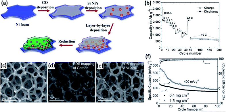 |
| | Fig. 15 (a) Schematic preparation process for multilayered Si/RGO electrode. (b) Rate capability of the multilayered Si/RGO electrode at various current rates as marked. Reprinted with permission from ref. 197. Copyright 2013 WILEY-VCH Verlag GmbH & Co. KGaA, Weinheim. (c) SEM image of the structure of Si/G dropped on UGF. EDS element mapping images of (d) C and (e) Si acquired at the same region as in (c). (f) Cycling performance and Coulombic efficiency of the Si/G/UGF electrodes at a current density of 0.4 A g−1. Reprinted with permission from ref. 201. Copyright 2013 WILEY-VCH Verlag GmbH & Co. KGaA, Weinheim. | |
5. Summary and future perspectives
Silicon with a large gravimetric capacity and low lithium alloying potential has been regarded as one of the most promising anode materials for the development of LIBs with high energy densities and attracted considerable attention. However, silicon materials with low intrinsic electric and ionic conductivity suffer from large volume expansion during cycling, leading to rapid capacity decay. In the past decade, a variety of strategies, such as structure and morphology control, surface and interface modification, electrolyte additive incorporation, novel polymer binder development, and appropriate current collector selection, have been developed and successfully improved the electrochemical performance of Si electrodes. Si nanostructures with controlled morphologies, such as thin films, nanosheets, nanorods, nanowires, nanotubes, hollow spheres, and hierarchically porous structures provide adequate void space to accommodate the huge volume change of Si during the lithiation and delithiation processes, enhancing the cycling stability. Moreover, these nanostructures facilitate electron transportation and Li+ diffusion, improving the rate capability. However, most of the research is focused on the gravimetric capacities of Si nanostructured electrodes. Given the high porosity and large specific surface area, the volumetric capacities of Si nanostructures are usually not as promising as their gravimetric capacities. The volumetric energy density of LIBs is critical for some particular applications, such as portable electronics.
Si nanoparticles with controlled particle size have relatively high tap densities, and consequently ensure the volumetric energy density of LIBs. To suppress the volume variation and modify the physicochemical property of the particle surface, many conductive species, including carbon coatings, carbon nanotubes and nanofibers, graphene nanosheets, metals, and conductive polymers, have been incorporated into Si nanoparticles to form a variety of composites. The introduction of conductive components to the Si nanoparticles can improve the electrical conductivity of the electrode, ensuring the high rate capability. The conductive components can alleviate the serious aggregation of Si nanoparticles, and suppress the large volume expansion of Si nanoparticles upon alloying with lithium. The formation of surface coating would prevent the direct contact of Si nanoparticles with the electrolyte, ensuring the generation of a stable SEI layer and consequently superior cycling stability. However, the content of the conductive components should be well controlled and optimized to achieve high volumetric energy density of LIBs.
The control of the structure and morphology, and incorporation of conductive components during the material design and preparation process are effective strategies in improving the electrochemical performance of Si electrodes. Parameters involved in the electrode and battery fabrication processes are also critical for the battery performance. The binders have an impact on the adhesion between current collectors and active materials and the integrity of the electrode upon cycling. Appropriate polymer binders and conductive additives involved in the electrode fabrication will decrease the inner resistance of the electrode, resulting in good rate and cycling performance. In addition, the addition of appropriate electrolyte additives can facilitate the formation of a thin and stable SEI layer, contributing to the cycling stability. The morphology and surface property of current collectors should also be well designed to ensure the firm attachment of the electrode layers with the current collector and reduce the electrical contact resistance.
Although the above-mentioned approaches can improve the performance of Si anodes effectively, low-cost, reliable, and large-scale preparation of Si materials with controlled nanostructure and morphology is still challenging, impacting on their practical and commercial application as anodes in LIBs. Further work is required to understand and optimize the lithium ion transport kinetics within the Si electrode and the interface between the electrode and electrolyte. In the consideration of full cell application, the gravimetric and volumetric capacities of Si electrodes and the content of conductive components during the formation of Si composites should be further optimized. Novel polymer binders and electrolyte additives should be developed. It is highly desirable that the cross-linking of these polymers can also provide sufficient pathways for electrons. The research on Si electrode materials is a hot topic in the energy storage field. It is believed that with the fast development in this field of science and technology, the issues that hinder the practical application of Si electrodes will be well addressed and LIBs with high energy density will be produced to meet the demand of stationary energy storage of renewable energy resources and electric vehicles.
Acknowledgements
This work was financially supported by the National Basic Research Program of China (2013CB934102 and 2014CB932102) and the National Natural Science Foundation of China (21271128, 21331004, 51472158).
Notes and references
- K. X. Wang, X. H. Li and J. S. Chen, Adv. Mater., 2015, 27, 527–545 CrossRef CAS PubMed.
- P. Roy and S. K. Srivastava, J. Mater. Chem. A, 2015, 3, 2454–2484 CAS.
- X. L. Wu, Y. G. Guo and L. J. Wan, Chem.–Asian J., 2013, 8, 1948–1958 CrossRef CAS PubMed.
- M. T. McDowell, S. W. Lee, W. D. Nix and Y. Cui, Adv. Mater., 2013, 25, 4966–4985 CrossRef CAS PubMed.
- M. R. Zamfir, H. T. Nguyen, E. Moyen, Y. H. Lee and D. Pribat, J. Mater. Chem. A, 2013, 1, 9566–9586 CAS.
- C. M. Park and H. J. Sohn, Adv. Mater., 2007, 19, 2465–2468 CrossRef CAS.
- L. Wang, X. He, J. Li, W. Sun, J. Gao, J. Guo and C. Jiang, Angew. Chem., Int. Ed., 2012, 51, 9034–9037 CrossRef CAS PubMed.
- Y. Wang, L. Tian, Z. Yao, F. Li, S. Li and S. Ye, Electrochim. Acta, 2015, 163, 71–76 CrossRef CAS.
- H. Jia, R. Kloepsch, X. He, J. P. Badillo, P. Gao, O. Fromm, T. Placke and M. Winter, Chem. Mater., 2014, 26, 5683–5688 CrossRef CAS.
- D. J. Xue, S. Xin, Y. Yan, K. C. Jiang, Y. X. Yin, Y. G. Guo and L. J. Wan, J. Am. Chem. Soc., 2012, 134, 2512–2515 CrossRef CAS PubMed.
- F. H. Du, Y. S. Liu, J. Long, Q. C. Zhu, K. X. Wang, X. Wei and J. S. Chen, Chem. Commun., 2014, 50, 9961–9964 RSC.
- J. Qin, C. He, N. Zhao, Z. Wang, C. Shi, E. Z. Liu and J. Li, ACS Nano, 2014, 8, 1728–1738 CrossRef CAS PubMed.
- Z. Wen, S. Cui, H. Kim, S. Mao, K. Yu, G. Lu, H. Pu, O. Mao and J. Chen, J. Mater. Chem., 2012, 22, 3300–3306 RSC.
- H. Hou, X. Tang, M. Guo, Y. Shi, P. Dou and X. Xu, Mater. Lett., 2014, 128, 408–411 CrossRef CAS.
- S. L. Chou, X. W. Gao, J. Z. Wang, D. Wexler, Z. X. Wang, L. Q. Chen and H. K. Liu, Dalton Trans., 2011, 40, 12801–12807 RSC.
- G. Zhang, J. Zhu, W. Zeng, S. Hou, F. Gong, F. Li, C. C. Li and H. Duan, Nano Energy, 2014, 9, 61–70 CrossRef CAS.
- H. Wu and Y. Cui, Nano Today, 2012, 7, 414–429 CrossRef CAS.
- X. Su, Q. Wu, J. Li, X. Xiao, A. Lott, W. Lu, B. W. Sheldon and J. Wu, Adv. Energy Mater., 2014, 4, 1300882 Search PubMed.
- X. Chen, C. Li, M. Gratzel, R. Kostecki and S. S. Mao, Chem. Soc. Rev., 2012, 41, 7909–7937 RSC.
- H. Jung, M. Park, S. H. Han, H. Lim and S. K. Joo, Solid State Commun., 2003, 125, 387–390 CrossRef CAS.
- H. Jung, M. Park, Y. G. Yoon, G. B. Kim and S. K. Joo, J. Power Sources, 2003, 115, 346–351 CrossRef CAS.
- J. Graetz, C. C. Ahn, R. Yazami and B. Fultz, Electrochem. Solid-State Lett., 2003, 6, A194–A197 CrossRef CAS.
- G. Zhao, Y. Meng, N. Zhang and K. Sun, Mater. Lett., 2012, 76, 55–58 CrossRef CAS.
- H. Xia, S. Tang and L. Lu, Mater. Res. Bull., 2007, 42, 1301–1309 CrossRef CAS.
- C. Pereira-Nabais, J. Swiatowska, M. Rosso, F. Ozanam, A. Seyeux, A. Gohier, P. Tran-Van, M. Cassir and P. Marcus, ACS Appl. Mater. Interfaces, 2014, 6, 13023–13033 CAS.
- M. S. Park, G. X. Wang, H. K. Liu and S. X. Dou, Electrochim. Acta, 2006, 51, 5246–5249 CrossRef CAS.
- L. B. Chen, J. Y. Xie, H. C. Yu and T. H. Wang, J. Appl. Electrochem., 2009, 39, 1157–1162 CrossRef CAS.
- T. Takamura, S. Ohara, M. Uehara, J. Suzuki and K. Sekine, J. Power Sources, 2004, 129, 96–100 CrossRef CAS.
- J. Yin, M. Wada, K. Yamamoto, Y. Kitano, S. Tanase and T. Sakai, J. Electrochem. Soc., 2006, 153, A472–A477 CrossRef CAS.
- C. K. Chan, H. Peng, G. Liu, K. Mcllwrath, X. F. Zhang, R. A. Huggins and Y. Cui, Nat. Nanotechnol., 2008, 3, 31–35 CrossRef CAS PubMed.
- K. Peng, J. Jie, W. Zhang and S. T. Lee, Appl. Phys. Lett., 2008, 93, 033105 CrossRef.
- P. P. Prosini, C. Cento, F. Alessandrini, P. Gislon, A. Mancini, A. Rufoloni, F. Rondino and A. Santoni, Solid State Ionics, 2014, 260, 49–54 CrossRef CAS.
- K. Q. Peng, X. Wang, L. Li, Y. Hu and S. T. Lee, Nano Today, 2013, 8, 75–97 CrossRef CAS.
- A. Gohier, B. Laïk, J. P. Pereira-Ramos, C. S. Cojocaru and P. Tran Van, J. Power Sources, 2012, 203, 135–139 CrossRef CAS.
- Y. Xiao, D. Hao, H. Chen, Z. Gong and Y. Yang, ACS Appl. Mater. Interfaces, 2013, 5, 1681–1687 CAS.
- Z. Wen, Z. Zhang and G. Wang, RSC Adv., 2014, 4, 57430–57435 RSC.
- A. M. Chockla, K. C. Klavetter, C. B. Mullins and B. A. Korgel, Chem. Mater., 2012, 24, 3738–3745 CrossRef CAS.
- Z. Wen, J. Stark, R. Saha, J. Parker and P. A. Kohl, J. Phys. Chem. C, 2013, 117, 8604–8610 CAS.
- H. T. Nguyen, F. Yao, M. R. Zamfir, C. Biswas, K. P. So, Y. H. Lee, S. M. Kim, S. N. Cha, J. M. Kim and D. Pribat, Adv. Energy Mater., 2011, 1, 1154–1161 CrossRef CAS.
- N. S. Hieu, J. C. Lim and J. K. Lee, Microelectron.
Eng., 2012, 89, 138–140 CrossRef CAS.
- S. H. Nguyen, J. C. Lim and J. K. Lee, Electrochim. Acta, 2012, 74, 53–58 CrossRef CAS.
- R. Teki, M. K. Datta, R. Krishnan, T. C. Parker, T. M. Lu, P. N. Kumta and N. Koratkar, Small, 2009, 5, 2236–2242 CrossRef CAS PubMed.
- Y. Zhou, X. Jiang, L. Chen, J. Yue, H. Xu, J. Yang and Y. Qian, Electrochim. Acta, 2014, 127, 252–258 CrossRef CAS.
- H. Ghassemi, M. Au, N. Chen, P. A. Heiden and R. S. Yassar, ACS Nano, 2011, 5, 7805–7811 CrossRef CAS PubMed.
- S. Soleimani-Amiri, S. A. S. Tali, S. Azimi, Z. Sanaee and S. Mohajerzadeh, Appl. Phys. Lett., 2014, 105, 193903 CrossRef.
- Z. Bao, M. R. Weatherspoon, S. Shian, Y. Cai, P. D. Graham, S. M. Allan, G. Ahmad, M. B. Dickerson, B. C. Church, Z. Kang, H. W. Abernathy III, C. J. Summers, M. Liu and K. H. Sandhage, Nature, 2007, 446, 172–175 CrossRef CAS PubMed.
- Z. Lu, J. Zhu, D. Sim, W. Zhou, W. Shi, H. H. Hng and Q. Yan, Chem. Mater., 2011, 23, 5293–5295 CrossRef CAS.
- X. Yu, F. Xue, H. Huang, C. Liu, J. Yu, Y. Sun, X. Dong, G. Cao and Y. Jung, Nanoscale, 2014, 6, 6860–6865 RSC.
- M. H. Park, M. G. Kim, J. Joo, K. Kim, J. Kim, S. Ahn, Y. Cui and J. Cho, Nano Lett., 2009, 9, 3844–3847 CrossRef CAS PubMed.
- J. K. Yoo, J. Kim, Y. S. Jung and K. Kang, Adv. Mater., 2012, 24, 5452–5456 CrossRef CAS PubMed.
- H. Wu, G. Chan, J. W. Choi, I. Ryu, Y. Yao, M. T. McDowell, S. W. Lee, A. Jackson, Y. Yang, L. Hu and Y. Cui, Nat. Nanotechnol., 2012, 7, 310–315 CrossRef CAS PubMed.
- Y. Yao, M. T. McDowell, I. Ryu, H. Wu, N. Liu, L. Hu, W. D. Nix and Y. Cui, Nano Lett., 2011, 11, 2949–2954 CrossRef CAS PubMed.
- D. Chen, X. Mei, G. Ji, M. Lu, J. Xie, J. Lu and J. Y. Lee, Angew. Chem., Int. Ed., 2012, 51, 2409–2413 CrossRef CAS PubMed.
- M. Ge, J. Rong, X. Fang, A. Zhang, Y. Lu and C. Zhou, Nano Res., 2013, 6, 174–181 CrossRef CAS.
- B. M. Bang, J. I. Lee, H. Kim, J. Cho and S. Park, Adv. Energy Mater., 2012, 2, 878–883 CrossRef CAS.
- M. Ge, Y. Lu, P. Ercius, J. Rong, X. Fang, M. Mecklenburg and C. Zhou, Nano Lett., 2014, 14, 261–268 CrossRef CAS PubMed.
- A. Esmanski and G. A. Ozin, Adv. Funct. Mater., 2009, 19, 1999–2010 CrossRef CAS.
- H. Kim, B. Han, J. Choo and J. Cho, Angew. Chem., Int. Ed., 2008, 47, 10151–10154 CrossRef CAS PubMed.
- Y. Yu, L. Gu, C. Zhu, S. Tsukimoto, P. A. van Aken and J. Maier, Adv. Mater., 2010, 22, 2247–2250 CrossRef CAS PubMed.
- H. Jia, P. Gao, J. Yang, J. Wang, Y. Nuli and Z. Yang, Adv. Energy Mater., 2011, 1, 1036–1039 CrossRef CAS.
- P. Gao, H. Jia, J. Yang, Y. Nuli, J. Wang and J. Chen, Phys. Chem. Chem. Phys., 2011, 13, 20108–20111 RSC.
- D. P. Wong, R. Suriyaprabha, R. Yuvakumar, V. Rajendran, Y. T. Chen, B. J. Hwang, L. C. Chen and K. H. Chen, J. Mater. Chem. A, 2014, 2, 13437–13441 CAS.
- N. Liu, K. Huo, M. T. McDowell, J. Zhao and Y. Cui, Sci. Rep., 2013, 3, 1919 Search PubMed.
- A. Xing, S. Tian, H. Tang, D. Losic and Z. Bao, RSC Adv., 2013, 3, 10145–10149 RSC.
- M. S. Wang, L. Z. Fan, M. Huang, J. Li and X. Qu, J. Power Sources, 2012, 219, 29–35 CrossRef CAS.
- L. Shen, X. Guo, X. Fang, Z. Wang and L. Chen, J. Power Sources, 2012, 213, 229–232 CrossRef CAS.
- Y. Zhao, X. Liu, H. Li, T. Zhai and H. Zhou, Chem. Commun., 2012, 48, 5079–5081 RSC.
- Y. Liu, B. Chen, F. Cao, H. L. W. Chan, X. Zhao and J. Yuan, J. Mater. Chem., 2011, 21, 17083–17086 RSC.
- M. Ge, X. Fang, J. Rong and C. Zhou, Nanotechnology, 2013, 24, 422001 CrossRef CAS PubMed.
- A. Magasinski, P. Dixon, B. Hertzberg, A. Kvit, J. Ayala and G. Yushin, Nat. Mater., 2010, 9, 353–358 CrossRef CAS PubMed.
- J. Yu, J. Yang, X. Feng, H. Jia, J. Wang and W. Lu, Ind. Eng. Chem. Res., 2014, 53, 12697–12704 CrossRef CAS.
- H. Tao, L. Z. Fan, W. L. Song, M. Wu, X. He and X. Qu, Nanoscale, 2014, 6, 3138–3142 RSC.
- N. Liu, Z. Lu, J. Zhao, M. T. McDowell, H. W. Lee, W. Zhao and Y. Cui, Nat. Nanotechnol., 2014, 9, 187–192 CrossRef CAS PubMed.
- M. S. Wang and L. Z. Fan, J. Power Sources, 2013, 244, 570–574 CrossRef CAS.
- H. H. Li, J. W. Wang, X. L. Wu, H. Z. Sun, F. M. Yang, K. Wang, L. L. Zhang, C. Y. Fan and J. P. Zhang, RSC Adv., 2014, 4, 36218–36225 RSC.
- Y. Park, N. S. Choi, S. Park, S. H. Woo, S. Sim, B. Y. Jang, S. M. Oh, S. Park, J. Cho and K. T. Lee, Adv. Energy Mater., 2013, 3, 206–212 CrossRef CAS.
- L. Pan, H. Wang, D. Gao, S. Chen, L. Tan and L. Li, Chem. Commun., 2014, 50, 5878–5880 RSC.
- M. S. Wang, Y. Song, W. L. Song and L. Z. Fan, ChemElectroChem, 2014, 1, 2124–2130 CrossRef CAS.
- J. Park, G. P. Kim, I. Nam, S. Park and J. Yi, Nanotechnology, 2013, 24, 025602 CrossRef PubMed.
- W. H. Lee, D. Y. Kang, J. S. Kim, J. K. Lee and J. H. Moon, RSC Adv., 2015, 5, 17424–17428 RSC.
- X. Li, P. Meduri, X. Chen, W. Qi, M. H. Engelhard, W. Xu, F. Ding, J. Xiao, W. Wang, C. Wang, J. G. Zhang and J. Liu, J. Mater. Chem., 2012, 22, 11014–11017 RSC.
- S. Chen, M. L. Gordin, R. Yi, G. Howlett, H. Sohn and D. Wang, Phys. Chem. Chem. Phys., 2012, 14, 12741–12745 RSC.
- P. Gao, J. Fu, J. Yang, R. Lv, J. Wang, Y. Nuli and X. Tang, Phys. Chem. Chem. Phys., 2009, 11, 11101–11105 RSC.
- R. D. Cakan, M. M. Titirici, M. Antonietti, G. Cui, J. Maier and Y. S. Hu, Chem. Commun., 2008, 3759–3761 RSC.
- J. Bae, Colloid Polym. Sci., 2011, 289, 1233–1241 CAS.
- S. H. Ng, J. Wang, D. Wexler, K. Konstantinov, Z. P. Guo and H. K. Liu, Angew. Chem., Int. Ed., 2006, 45, 6896–6899 CrossRef CAS PubMed.
- X. Y. Zhou, J. J. Tang, J. Yang, J. Xie and L. L. Ma, Electrochim. Acta, 2013, 87, 663–668 CrossRef CAS.
- N. Liu, H. Wu, M. T. McDowell, Y. Yao, C. Wang and Y. Cui, Nano Lett., 2012, 12, 3315–3321 CrossRef CAS PubMed.
- L. Su, J. Xie, Y. Xu, L. Wang, Y. Wang and M. Ren, Phys. Chem. Chem. Phys., 2015, 17, 17562–17565 RSC.
- L. Su, Z. Zhou and M. Ren, Chem. Commun., 2010, 46, 2590–2592 RSC.
- T. H. Hwang, Y. M. Lee, B. S. Kong, J. S. Seo and J. W. Choi, Nano Lett., 2012, 12, 802–807 CrossRef CAS PubMed.
- X. Zhou, L. J. Wan and Y. G. Guo, Small, 2013, 9, 2684–2688 CrossRef CAS PubMed.
- D. Nan, Z. H. Huang, R. Lv, Y. Lin, L. Yang, X. Yu, L. Ye, W. Shen, H. Sun and F. Kang, J. Nanomater., 2014, 139639 Search PubMed.
- Y. Li, Z. Lin, G. Xu, Y. Yao, S. Zhang, O. Toprakci, M. Alcoutlabi and X. Zhang, ECS Electrochem. Lett., 2012, 1, A31–A33 CrossRef CAS.
- Z. L. Xu, B. Zhang, S. Abouali, M. A. Garakani, J. Huang, J. Q. Huang, E. K. Heidari and J. K. Kim, J. Mater. Chem. A, 2014, 2, 17944–17951 CAS.
- H. P. Liu, W. M. Qiao, L. Zhan and L. C. Ling, New Carbon Mater., 2009, 24, 124–130 CrossRef CAS.
- L. Ji and X. Zhang, Electrochem. Commun., 2009, 11, 1146–1149 CrossRef CAS.
- B. S. Lee, S. B. Son, K. M. Park, J. H. Seo, S. H. Lee, I. S. Choi, K. H. Oh and W. R. Yu, J. Power Sources, 2012, 206, 267–273 CrossRef CAS.
- Y. Liu, K. Huang, Y. Fan, Q. Zhang, F. Sun, T. Gao, Z. Wang and J. Zhong, Electrochim. Acta, 2013, 102, 246–251 CrossRef CAS.
- Y. Li, B. Guo, L. Ji, Z. Lin, G. Xu, Y. Liang, S. Zhang, O. Toprakci, Y. Hu, M. Alcoutlabi and X. Zhang, Carbon, 2013, 51, 185–194 CrossRef CAS.
- L. Ji and X. Zhang, Carbon, 2009, 47, 3219–3226 CrossRef CAS.
- W. Wang and P. N. Kumta, ACS Nano, 2010, 4, 2233–2241 CrossRef CAS PubMed.
- C. Martin, O. Crosnier, R. Retoux, D. Belanger, D. M. Schleich and T. Brousse, Adv. Funct. Mater., 2011, 21, 3524–3530 CrossRef CAS.
- A. Gohier, B. Laik, K. H. Kim, J. L. Maurice, J. P. Pereira-Ramos, C. S. Cojocaru and P. T. Van, Adv. Mater., 2012, 24, 2592–2597 CrossRef CAS PubMed.
- Y. S. Na, S. Choi and D. W. Park, Phys. Status Solidi A, 2014, 211, 2749–2755 CrossRef CAS.
- Y. Fan, Q. Zhang, Q. Xiao, X. Wang and K. Huang, Carbon, 2013, 59, 264–269 CrossRef CAS.
- L. Yue, H. Zhong and L. Zhang, Electrochim. Acta, 2012, 76, 326–332 CrossRef CAS.
- R. Epur, M. K. Datta and P. N. Kumta, Electrochim. Acta, 2012, 85, 680–684 CrossRef CAS.
- Y. S. Na, H. Yoo, T. H. Kim, J. Choi, W. I. Lee, S. Choi and D. W. Park, Thin Solid Films, 2015, 587, 14–19 CrossRef CAS.
- T. Cetinkaya, M. O. Guler and H. Akbulut, Microelectron. Eng., 2013, 108, 169–176 CrossRef CAS.
- W. J. Yu, C. Liu, P. X. Hou, L. Zhang, X. Y. Shan, F. Li and H. M. Cheng, ACS Nano, 2015, 9, 5063–5071 CrossRef CAS PubMed.
- N. Coppey, L. Noe, M. Monthioux and B. Caussat, Chem. Eng. Res. Des., 2013, 91, 2491–2496 CrossRef CAS.
- B. G. Kim, W. H. Shin, S. Y. Lim, B. S. Kong and J. W. Choi, J. Electrochem. Sci. Technol., 2012, 3, 116–122 CrossRef CAS.
- V. Chabot, K. Feng, H. W. Park, F. M. Hassan, A. R. Elsayed, A. Yu, X. Xiao and Z. Chen, Electrochim. Acta, 2014, 130, 127–134 CrossRef CAS.
- J. Zhang, L. Zhang, P. Xue, L. Zhang, X. Zhang, W. Hao, J. Tian, M. Shen and H. Zheng, J. Mater. Chem. A, 2015, 3, 7810–7821 CAS.
- J. G. Ren, Q. H. Wu, G. Hong, W. J. Zhang, H. Wu, K. Amine, J. Yang and S. T. Lee, Energy Technol., 2013, 1, 77–84 CrossRef CAS.
- Y. Wen, Y. Zhu, A. Langrock, A. Manivannan, S. H. Ehrman and C. Wang, Small, 2013, 9, 2810–2816 CrossRef CAS PubMed.
- X. Zhou, Y. X. Yin, L. J. Wan and Y. G. Guo, Adv. Energy Mater., 2012, 2, 1086–1090 CrossRef CAS.
- H. Xiang, K. Zhang, G. Ji, J. Y. Lee, C. Zou, X. Chen and J. Wu, Carbon, 2011, 49, 1787–1796 CrossRef CAS.
- Y. S. He, P. Gao, J. Chen, X. Yang, X. Z. Liao, J. Yang and Z. F. Ma, RSC Adv., 2011, 1, 958–960 RSC.
- J. Luo, X. Zhao, J. Wu, H. D. Jang, H. H. Kung and J. Huang, J. Phys. Chem. Lett., 2012, 3, 1824–1829 CrossRef CAS PubMed.
- X. Zhou, Y. X. Yin, L. J. Wan and Y. G. Guo, Chem. Commun., 2012, 48, 2198–2200 RSC.
- G. Zhao, L. Zhang, Y. Meng, N. Zhang and K. Sun, J. Power Sources, 2013, 240, 212–218 CrossRef CAS.
- F. Maroni, R. Raccichini, A. Birrozzi, G. Carbonari, R. Tossici, F. Croce, R. Marassi and F. Nobili, J. Power Sources, 2014, 269, 873–882 CrossRef CAS.
- H. Tang, J. Zhang, Y. J. Zhang, Q. Q. Xiong, Y. Y. Tong, Y. Li, X. L. Wang, C. D. Gu and J. P. Tu, J. Power Sources, 2015, 286, 431–437 CrossRef CAS.
- S. L. Chou, J. Z. Wang, M. Choucair, H. K. Liu, J. A. Stride and S. X. Dou, Electrochem. Commun., 2010, 12, 303–306 CrossRef CAS.
- X. Zhao, C. M. Hayner, M. C. Kung and H. H. Kung, Adv. Energy Mater., 2011, 1, 1079–1084 CrossRef CAS.
- Y. Chen, X. Zhang, Y. Tian and X. Zhao, J. Nanomater., 2014, 734751 Search PubMed.
- D. P. Wong, H. P. Tseng, Y. T. Chen, B. J. Hwang, L. C. Chen and K. H. Chen, Carbon, 2013, 63, 397–403 CrossRef CAS.
- Y. S. Ye, X. L. Xie, J. Rick, F. C. Chang and B. J. Hwang, J. Power Sources, 2014, 247, 991–998 CrossRef CAS.
- S. Yang, G. Li, Q. Zhu and Q. Pan, J. Mater. Chem., 2012, 22, 3420–3425 RSC.
- N. Lin, J. Zhou, Y. Zhu and Y. Qian, J. Mater. Chem. A, 2014, 2, 19604–19608 CAS.
- B. Xu, H. Wu, C. X. Lin, B. Wang, Z. Zhang and X. S. Zhao, RSC Adv., 2015, 5, 30624–30630 RSC.
- R. C. de Guzman, J. Yang, M. M. C. Cheng, S. O. Salley and K. Y. S. Ng, J. Mater. Sci., 2013, 48, 4823–4833 CrossRef CAS.
- S. Yoo, J. I. Lee, S. Ko and S. Park, Nano Energy, 2013, 2, 1271–1278 CrossRef CAS.
- S. Murugesan, J. T. Harris, B. A. Korgel and K. J. Stevenson, Chem. Mater., 2012, 24, 1306–1315 CrossRef CAS.
- S. Yang and Q. Pan, Electrochem. Solid-State Lett., 2011, 14, A180–A184 CrossRef CAS.
- X. Yang, Z. Wen, S. Huang, X. Zhu and X. Zhang, Solid State Ionics, 2006, 177, 2807–2810 CrossRef CAS.
- Z. P. Guo, J. Z. Wang, H. K. Liu and S. X. Dou, J. Power Sources, 2005, 146, 448–451 CrossRef CAS.
- H. Wu, G. Yu, L. Pan, N. Liu, M. T. McDowell, Z. Bao and Y. Cui, Nat. Commun., 2013, 4, 1943 Search PubMed.
- M. Kummer, J. P. Badillo, A. Schmitz, H. G. Bremes, M. Winter, C. Schulz and H. Wiggers, J. Electrochem. Soc., 2014, 161, A40–A45 CrossRef CAS.
- M. Feng, J. Tian, H. Xie, Y. Kang and Z. Shan, J. Solid State Electrochem., 2015, 19, 1773–1782 CrossRef CAS.
- X. Y. Zhou, J. J. Tang, J. Yang, Y. L. Zou, S. C. Wang, J. Xie and L. L. Ma, Electrochim. Acta, 2012, 70, 296–303 CrossRef CAS.
- S. Y. Chew, Z. P. Guo, J. Z. Wang, J. Chen, P. Munroe, S. H. Ng, L. Zhao and H. K. Liu, Electrochem. Commun., 2007, 9, 941–946 CrossRef CAS.
- H. S. La, K. S. Park, K. S. Nahm, K. K. Jeong and Y. S. Lee, Colloids Surf., A, 2006, 272, 22–26 CrossRef CAS.
- H. C. Tao, X. L. Yang, L. L. Zhang and S. B. Ni, J. Solid State Electrochem., 2014, 18, 1989–1994 CrossRef CAS.
- M. Gu, X. C. Xiao, G. Liu, S. Thevuthasan, D. R. Baer, J. G. Zhang, J. Liu, N. D. Browning and C. M. Wang, Sci. Rep., 2014, 4, 3684 Search PubMed.
- L. Su, Y. Jing and Z. Zhou, Nanoscale, 2011, 3, 3967–3983 RSC.
- P. Zhang, L. Wang, J. Xie, L. Su and C. A. Ma, J. Mater. Chem. A, 2014, 2, 3776–3782 CAS.
- F. H. Du, K. X. Wang, W. Fu, P. F. Gao, J. F. Wang, J. Yang and J. S. Chen, J. Mater. Chem. A, 2013, 1, 13648–13654 CAS.
- F. H. Du, B. Li, W. Fu, Y. J. Xiong, K. X. Wang and J. S. Chen, Adv. Mater., 2014, 26, 6145–6150 CrossRef CAS PubMed.
- M. Q. Li, M. Z. Qu, X. Y. He and Z. L. Yu, Electrochim. Acta, 2009, 54, 4506–4513 CrossRef CAS.
- L. Chen, K. Wang, X. Xie and J. Xie, J. Power Sources, 2007, 174, 538–543 CrossRef CAS.
- M. Ulldemolins, F. Le Cras, B. Pecquenard, V. P. Phan, L. Martin and H. Martinez, J. Power Sources, 2012, 206, 245–252 CrossRef CAS.
- Y. Xiao, D. Hao, H. Chen, Z. Gong and Y. Yang, ACS Appl. Mater. Interfaces, 2013, 5, 1681–1687 CAS.
- L. Chen, K. Wang, X. Xie and J. Xie, Electrochem. Solid-State Lett., 2006, 9, A512–A515 CrossRef CAS.
- S. Dalavi, P. Guduru and B. L. Lucht, J. Electrochem. Soc., 2012, 159, A642–A646 CrossRef CAS.
- I. A. Profatilova, C. Stock, A. Schmitz, S. Passerini and M. Winter, J. Power Sources, 2013, 222, 140–149 CrossRef CAS.
- C. C. Nguyen and B. L. Lucht, J. Electrochem. Soc., 2014, 161, A1933–A1938 CrossRef.
- G. B. Han, J. N. Lee, J. W. Choi and J. K. Park, Electrochim. Acta, 2011, 56, 8997–9003 CrossRef CAS.
- G. B. Han, M. H. Ryou, K. Y. Cho, Y. M. Lee and J. K. Park, J. Power Sources, 2010, 195, 3709–3714 CrossRef CAS.
- Y. Li, G. Xu, Y. Yao, L. Xue, S. Zhang, Y. Lu, O. Toprakci and X. Zhang, J. Solid State Electrochem., 2013, 17, 1393–1399 CrossRef CAS.
- C. Xu, F. Lindgren, B. Philippe, M. Gorgoi, F. Bjorefors, K. Edstrom and T. Gustafsson, Chem. Mater., 2015, 27, 2591–2599 CrossRef CAS.
- X. Chen, X. Li, D. Mei, J. Feng, M. Y. Hu, J. Hu, M. Engelhard, J. Zheng, W. Xu, J. Xiao, J. Liu and J. G. Zhang, ChemSusChem, 2014, 7, 549–554 CrossRef CAS PubMed.
- K. Leung, S. B. Rempe, M. E. Foster, Y. Ma, J. M. Martinez del la Hoz, N. Sai and P. B. Balbuena, J. Electrochem. Soc., 2014, 161, A213–A221 CrossRef CAS.
- H. Nakai, T. Kubota, A. Kita and A. Kawashima, J. Electrochem. Soc., 2011, 158, A798–A801 CrossRef CAS.
- Y. K. Jeong, T. W. Kwon, I. Lee, T. S. Kim, A. Coskun and J. W. Choi, Energy Environ. Sci., 2015, 8, 1224–1230 CAS.
- A. Magasinski, B. Zdyrko, I. Kovalenko, B. Hertzberg, R. Burtovyy, C. F. Huebner, T. F. Fuller, I. Luzinov and G. Yushin, ACS Appl. Mater. Interfaces, 2010, 2, 3004–3010 CAS.
- B. Lestriez, S. Bahri, I. Sandu, L. Roue and D. Guyomard, Electrochem. Commun., 2007, 9, 2801–2806 CrossRef CAS.
- D. Shao, H. Zhong and L. Zhang, ChemElectroChem, 2014, 1, 1679–1687 CrossRef CAS.
- J. Guo and C. Wang, Chem. Commun., 2010, 46, 1428–1430 RSC.
- I. Kovalenko, B. Zdyrko, A. Magasinski, B. Hertzberg, Z. Milicev, R. Burtovyy, I. Luzinov and G. Yushin, Science, 2011, 334, 75–79 CrossRef CAS PubMed.
- J. Liu, Q. Zhang, Z. Y. Wu, J. H. Wu, J. T. Li, L. Huang and S. G. Sun, Chem. Commun., 2014, 50, 6386–6389 RSC.
- J. Yoon, D. X. Oh, C. Jo, J. Lee and D. S. Hwang, Phys. Chem. Chem. Phys., 2014, 16, 25628–25635 RSC.
- L. Zhang, L. Zhang, L. Chai, P. Xue, W. Hao and H. Zheng, J. Mater. Chem. A, 2014, 2, 19036–19045 CAS.
- M. H. Ryou, J. Kim, I. Lee, S. Kim, Y. K. Jeong, S. Hong, J. H. Ryu, T. S. Kim, J. K. Park, H. Lee and J. W. Choi, Adv. Mater., 2013, 25, 1571–1576 CrossRef CAS PubMed.
- M. Wu, X. Xiao, N. Vukmirovic, S. Xun, P. K. Das, X. Song, P. Olalde-Velasco, D. Wang, A. Z. Weber, L. W. Wang, V. S. Battaglia, W. Yang and G. Liu, J. Am. Chem. Soc., 2013, 135, 12048–12056 CrossRef CAS PubMed.
- B. Koo, H. Kim, Y. Cho, K. T. Lee, N. S. Choi and J. Cho, Angew. Chem., Int. Ed., 2012, 51, 8762–8767 CrossRef CAS PubMed.
- J. Song, M. Zhou, R. Yi, T. Xu, M. L. Gordin, D. Tang, Z. Yu, M. Regula and D. Wang, Adv. Funct. Mater., 2014, 24, 5904–5910 CrossRef CAS.
- L. Shen, L. Shen, Z. Wang and L. Chen, ChemSusChem, 2014, 7, 1951–1956 CrossRef CAS PubMed.
- Y. Park, S. Lee, S. H. Kim, B. Y. Jang, J. S. Kim, S. M. Oh, J. Y. Kim, N. S. Choi, K. T. Lee and B. S. Kim, RSC Adv., 2013, 3, 12625–12630 RSC.
- Z. J. Han, N. Yabuuchi, S. Hashimoto, T. Sasaki and S. Komaba, ECS Electrochem. Lett., 2013, 2, A17–A20 CrossRef CAS.
- T. Yim, S. J. Choi, J. H. Park, W. Cho, Y. N. Jo, T. H. Kim and Y. J. Kim, Phys. Chem. Chem. Phys., 2015, 17, 2388–2393 RSC.
- Z. Chen, C. Wang, J. Lopez, Z. Lu, Y. Cui and Z. Bao, Adv. Energy Mater., 2015, 5, 1401826 Search PubMed.
- C. Wang, H. Wu, Z. Chen, M. T. McDowell, Y. Cui and Z. Bao, Nat. Chem., 2013, 5, 1042–1048 CrossRef CAS PubMed.
- L. Yue, L. Zhang and H. Zhong, J. Power Sources, 2014, 247, 327–331 CrossRef CAS.
- T. W. Kwon, Y. K. Jeong, I. Lee, T. S. Kim, J. W. Choi and A. Coskun, Adv. Mater., 2014, 26, 7979–7985 CrossRef CAS PubMed.
- S. J. Park, H. Zhao, G. Ai, C. Wang, X. Song, N. Yuca, V. S. Battaglia, W. Yang and G. Liu, J. Am. Chem. Soc., 2015, 137, 2565–2571 CrossRef CAS PubMed.
- M. Ling, Y. Xu, H. Zhao, X. Gu, J. Qiu, S. Li, M. Wu, X. Song, C. Yan, G. Liu and S. Zhang, Nano Energy, 2015, 12, 178–185 CrossRef CAS.
- Y. E. Roginskaya, T. L. Kulova, A. M. Skundin, M. A. Bruk, E. N. Zhikharev and V. A. Kal'nov, Russ. J. Electrochem., 2008, 44, 992–1001 CrossRef CAS.
- H. Guo, H. Zhao, C. Yin and W. Qiu, Mater. Sci. Eng., B, 2006, 131, 173–176 CrossRef CAS.
- K. L. Lee, J. Y. Jung, S. W. Lee, H. S. Moon and J. W. Park, J. Power Sources, 2004, 129, 270–274 CrossRef CAS.
- T. Takamura, M. Uehara, J. Suzuki, K. Sekine and K. Tamura, J. Power Sources, 2006, 158, 1401–1404 CrossRef CAS.
- C. C. Nguyen and S. W. Song, Electrochim. Acta, 2010, 55, 3026–3033 CrossRef CAS.
- D. Reyter, S. Rousselot, D. Mazouzi, M. Gauthier, P. Moreau, B. Lestriez, D. Guyomard and L. Roue, J. Power Sources, 2013, 239, 308–314 CrossRef CAS.
- T. Zhang, H. P. Zhang, L. C. Yang, B. Wang, Y. P. Wu and T. Takamura, Electrochim. Acta, 2008, 53, 5660–5664 CrossRef CAS.
- J. Chang, X. Huang, G. Zhou, S. Cui, P. B. Hallac, J. Jiang, P. T. Hurley and J. Chen, Adv. Mater., 2014, 26, 758–764 CrossRef CAS PubMed.
- D. Mazouzi, D. Reyter, M. Gauthier, P. Moreau, D. Guyomard, L. Roue and B. Lestriez, Adv. Energy Mater., 2014, 4, 1301718 Search PubMed.
- C. Gao, H. Zhao, P. Lv, T. Zhang, Q. Xia and J. Wang, ACS Appl. Mater. Interfaces, 2015, 7, 1693–1698 CAS.
- X. Huang, H. Yu, J. Chen, Z. Lu, R. Yazami and H. H. Hng, Adv. Mater., 2014, 26, 1296–1303 CrossRef CAS PubMed.
- J. Ji, H. Ji, L. L. Zhang, X. Zhao, X. Bai, X. Fan, F. Zhang and R. S. Ruoff, Adv. Mater., 2013, 25, 4673–4677 CrossRef CAS PubMed.
- J. Z. Wang, C. Zhong, S. L. Chou and H. K. Liu, Electrochem. Commun., 2010, 12, 1467–1470 CrossRef CAS.
- H. C. Tao, L. Z. Fan, Y. Mei and X. Qu, Electrochem. Commun., 2011, 13, 1332–1335 CrossRef CAS.
- S. L. Chou, Y. Zhao, J. Z. Wang, Z. X. Chen, H. K. Liu and S. X. Dou, J. Phys. Chem. C, 2010, 114, 15862–15867 CAS.
|
| This journal is © The Royal Society of Chemistry 2016 |
Click here to see how this site uses Cookies. View our privacy policy here. 


![[thin space (1/6-em)]](https://www.rsc.org/images/entities/char_2009.gif) :
:![[thin space (1/6-em)]](https://www.rsc.org/images/entities/char_2009.gif) Si mass ratios of 2
Si mass ratios of 2![[thin space (1/6-em)]](https://www.rsc.org/images/entities/char_2009.gif) :
:![[thin space (1/6-em)]](https://www.rsc.org/images/entities/char_2009.gif) 5 (b), 4
5 (b), 4![[thin space (1/6-em)]](https://www.rsc.org/images/entities/char_2009.gif) :
:![[thin space (1/6-em)]](https://www.rsc.org/images/entities/char_2009.gif) 5 (c), and 8
5 (c), and 8![[thin space (1/6-em)]](https://www.rsc.org/images/entities/char_2009.gif) :
:![[thin space (1/6-em)]](https://www.rsc.org/images/entities/char_2009.gif) 5 (d), respectively. Reprinted with permission from ref. 54. Copyright 2013 Springer. (e) Schematic diagram of the procedure to prepare porous bulk Si. (f) SEM image of Ag-deposited Si. (g and h) SEM images of chemically etched Si. Reprinted with permission from ref. 55. Copyright 2012 WILEY-VCH Verlag GmbH & Co. KGaA, Weinheim. (i) Synthesis route of porous Si from metallurgical Si by a two-step approach combining ball milling and Fe-assisted chemical etching. (j) TEM image of porous Si particles. (K) STEM image of porous particles. Reprinted with permission from ref. 56. Copyright 2013 American Chemical Society.
5 (d), respectively. Reprinted with permission from ref. 54. Copyright 2013 Springer. (e) Schematic diagram of the procedure to prepare porous bulk Si. (f) SEM image of Ag-deposited Si. (g and h) SEM images of chemically etched Si. Reprinted with permission from ref. 55. Copyright 2012 WILEY-VCH Verlag GmbH & Co. KGaA, Weinheim. (i) Synthesis route of porous Si from metallurgical Si by a two-step approach combining ball milling and Fe-assisted chemical etching. (j) TEM image of porous Si particles. (K) STEM image of porous particles. Reprinted with permission from ref. 56. Copyright 2013 American Chemical Society.


