TiO2 as an active or supplemental material for lithium batteries
Taeseup
Song
a and
Ungyu
Paik
*b
aSchool of Materials Science and Engineering, Yeungnam University, Gyeongsan 712-749, Korea
bDepartment of Energy Engineering, Hanyang University, Seoul 133-791, Korea. E-mail: upaik@hanyang.ac.kr
First published on 3rd November 2015
Abstract
TiO2 has received significant research interest as an anode material for lithium ion batteries due to its robustness and safe operation. However, poor rate capabilities limit its practical use. Various strategies have been explored to address this issue by improving the electronic conductivity and enhancing the Li ion kinetics. Especially, surface facet control, doping and surface treatment of TiO2 enable significant improvement in kinetics associated with the electron and the Li ion without employing other foreign materials. Recent reports show that the unique physicochemical properties and well established technologies on engineering of TiO2 properties have opened up further possibilities in the next generation Li batteries and advanced Li ion batteries as a supplemental material. This review discusses recent scientific and technological advances in (i) the improvement in rate capabilities of TiO2 anodes from the engineering of their structural or electronic properties (ii) TiO2 as a supplemental material in Li–S and Li–O2 batteries and advanced Li ion batteries. In addition to highlighting recent progress, the limitations and challenges of TiO2 for Li ion batteries and next generation Li batteries have also been discussed.
1. Introduction
Titanium dioxide (TiO2) has been explored in various research areas, especially energy related devices.1–5 Its unique physicochemical properties are suitable for the application in energy harvesting systems including photocatalysts, water splitting devices and dye-sensitized solar cells.6–9 Significant research has been also directed toward its application as an anode material for lithium ion batteries due to its abundance, low cost and excellent structural ability associated with lithium.10,11 Furthermore, its high working voltage (more than 1.5 V vs. Li) enables stable operation without the formation of a solid electrolyte interface caused by the liquid electrolyte decomposition at low potential as well as extremely high rate operation by prohibiting lithium plating on the electrode.12 TiO2 is a typical Li+ intercalation compound. The Li ion intercalation–deintercalation reaction in anatase TiO2 could be described as follows:| TiO2 + XLi+ + Xe− = LiXTiO2, (0 ≤ X ≤ 1) | (1) |
There are three main factors dominating the rate capability of TiO2 anode materials; (1) the electronic conductivity in the electrode (film), (2) Li ion kinetics and (3) the electronic contact between the active material and metallic current collector. The electronic conductivity in the electrode (film) could be improved by morphology engineering, the enhancement of intrinsic electronic conductivity of TiO2 and (or) the introduction of highly conducting materials.2 One dimensional (1D) and three dimensional (3D) TiO2 structures have been intensively explored to improve the rate capability.4,17–19 Although these 1D and 3D structures benefit the facile electron transport along its 1D and 3D network, the improvement in electrical properties is limited due to intrinsically poor electronic conductivity of TiO2.4 The intrinsic electronic conductivity could be engineered by doping or through surface modification.12,20–24 Various carbonaceous materials, including carbon black, carbon nanotubes, graphene, and metal frames were utilized to improve the electronic conductivity in the electrode (film).25–31 Although mixing or coating of highly conducting materials with (or on) TiO2 is a facile way for the enhancement in electronic conductivity, these conducting materials are completely inactive with lithium in the operation voltage of TiO2, which results in the decrease in the volumetric capacity and gravimetric capacity of the electrode. Therefore, the enhancement in the electronic conductivity of TiO2 without the introduction of heavy metals or Li inactive functional materials is critical for its practical use. For the improvement in the Li ion kinetics, nanostructuring, exposed facet control, and mesoporous structures are generally proposed. TiO2 nanostructures from 0D to 3D have been introduced to enhance Li ion kinetics by shortening the Li ion diffusion length and enlarging Li ion flux at the interface between the active TiO2 material and the electrolyte. Although TiO2 nanostructures enable the improvement in Li ion kinetics as well as other advantages in the electrochemical behaviors, the tap density of the electrode composed of TiO2 nanostructures is significantly decreased. Low tap density is critical for the practical use of TiO2 based electrodes due to their low specific capacity and high operation voltage over 1 V. It is known that the energy barrier at the interface between the active material and the electrolyte is much higher than that for the bulk diffusion, which indicates that Li ion insertion at the surface plays a key role in enhancing the rate capabilities. In TiO2, the specific plane provides a fast interfacial charge transfer. Therefore, the Li ion kinetics could be improved by engineering the exposed surface. Mesoporous structures could significantly reduce the Li ion diffusion length and increase the Li ion flux at the interface.32 Specifically, the micro-sized mesoporous TiO2 material enables the improvement in Li ion kinetics without significant loss in the tap density. In this article, we introduce only the facet controlled TiO2 as nanostructured and mesoporous TiO2 were well summarized elsewhere.2,5,10,32 The electronic contact at the interface between the current collector and the active material in the electrode also plays an important role in the electronic conductivity of the overall electrode system.33 The electronic resistance at the interface is more critical in the micro-batteries adopting thin electrodes. In this article, we tried to provide strategies to improve the rate capability of the TiO2 based electrode by engineering the physicochemical properties of TiO2, such as doping, facet control, surface treatment and electrical contact between the current collector and TiO2, for the improvement of Li ion and electron kinetics without the introduction of heavy metals or Li inactive functional materials and modification of the geometry of TiO2 active materials as many previous review papers dealt with carbon (or metal)–TiO2 composites and geometry engineering.2,10,34,35
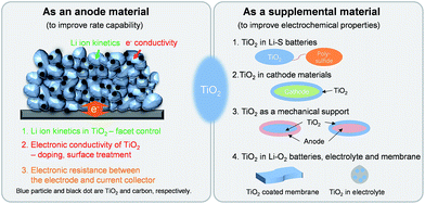
This article is mainly composed of two parts; (i) TiO2 as an anode material for Li ion batteries and (ii) TiO2 as a supplemental material in lithium batteries (Scheme 1). The unique physicochemical properties and previously developed methods for the modification of its properties could broaden the applicable fields to which TiO2 can be applied. TiO2 has been widely employed as a supplemental material in lithium batteries including Li–S,36–38 Li–O2,39–41 electrolyte,42,43 membrane44 and, cathode45,46 to improve the electrochemical properties. TiO2 show promise in the cycling improvement of Li–S batteries, in which it prevents physical polysulfide dissolution into the electrolyte and effectively adsorbs them by the strong interaction between TiO2 and sulfur. TiO2 was also employed as a coating material of the cathode for Li ion batteries to improve the structural stability and transition metal dissolution. TiO2 coating on the cathode results in improved and/or degraded electrochemical properties depending on the materials and evaluation conditions. Its excellent structural stability associated with lithium enables the utilization of TiO2 as a mechanical support against the pulverization of alloy type active materials to improve the cycle stability. TiO2 has been evaluated as a catalyst or cathode catalyst support to improve the electrochemical properties by improving the catalytic activity hindering the degradation caused by the decomposition of the carbon material and the electrolyte. Details will be discussed after the introduction of TiO2 as an anode material for Li ion batteries.
2. TiO2 as an anode material for Li ion batteries
2.1 Exposed facet control
It has been reported that anatase TiO2 crystals terminated with {001} facets show enhanced kinetics associated with Li-ion insertion/extraction, leading to improved electrochemical properties including the reversibility and rate capability.47–51 These improvements are attributed to the fast interfacial charge transfer at this surface and efficient Li ion diffusion along the [001] direction (c axis). The {001} facets of anatase TiO2 have a lower energy barrier (1.33 eV) for Li-ion insertion than that of through {101} facets (2.73 eV). These energy barriers are much higher than that for the bulk diffusion (0.35–0.65 eV),47,50,52,53 which implies that Li ion insertion at the surface plays a key role in the rate capability as it acts as a rate-determining step.47 Therefore, it is important to control the surface facets of anatase TiO2 for the improvement in the electrochemical properties by exploiting their surface properties. Generally, the anatase TiO2 crystals are terminated with {101} facets during crystal growth processes under the equilibrium condition due to their lower surface free energy (0.44 J m−2) compared to those of other low index facets including {001} (0.90 J m−2) and {100} (0.53 J m−2).50,52,53 Although TiO2 terminated with high-energy {001} facets is desirable, it is a challenge to control the surface facets of TiO2 due to the spontaneous formation of thermodynamically stable low-energy facets to minimize the total surface free energy.48,54,55 Various synthesis methods have been proposed to control the exposed facets and increase the percentage of high-energy {001} facets on the surface.55 Generally, for the synthetic processes for {001} facets, fluorine-containing species56–59 or fluorine-free species48,59,60 are usually used as a specific capping agent, which controls the growth rates to the specific crystal facets by selective adsorption of these species.Chen et al. reported on anatase TiO2 spheres self-organized from ultrathin TiO2 nanosheets (TiO2 NSHSs) with nearly 100% exposed (001) facets.48 Anatase TiO2 NSHSs were synthesized by a solvothermal method and using diethylenetriamine as a capping agent. As shown in Fig. 1(a)–(e), the TiO2 NSHSs, with an average size of ∼1 μm, are composed of randomly oriented TiO2 nanosheets of 3 nm thickness. In the given dimension and geometry, 95–99% of the exposed surfaces are {001} facets. The TiO2 NSHSs delivered a charge capacity of 204 mA h g−1 and a discharge capacity of 169 mA h g−1 in the first cycle with at a current rate of 5C (850 mA g−1), corresponding to a reversible capacity of 83%. The TiO2 NSHS electrode shows good rate capability. It exhibits specific capacities of 224, 192, 170 and 150 mA h g−1 at current rates of 0.5, 1, 5C and 10C, respectively. The improvement in the electrochemical properties are attributed to the short transport length along the [001] direction and favorable lithium insertion/extraction through {001} facets. Sun et al. prepared two types of anatase TiO2 nanocrystals with different percentages of (001)/(101) surfaces by hydrothermal processes with and without HF.61 The surface of nanosheet TiO2 synthesized with HF is mainly composed of {001} facets (∼80%) (Fig. 1(f) and (g)), and the surface of octahedral shaped TiO2 synthesized without HF is terminated with {101} facets (∼98%) (Fig. 1(h) and (i)). The nanosheet TiO2 electrode shows better reversibility in lithium insertion/extraction behavior in the cyclic voltammograms while octahedral shaped TiO2 exhibits continued shifting of the cathodic peak after the first scan (Fig. 1(j) and (k)). The nanosheet TiO2 electrode shows much improved electrochemical properties compared to those of octahedral shaped TiO2 at various current densities, which is attributed to a lower energy barrier for Li ion insertion across the {001} facets. Yang et al. synthesized two types of single-crystalline anatase TiO2 cubes terminated with both {100} and {001} facets with different sizes via a hydrothermal method in a quaternary solution containing 1-butyl-3-methylimidazolium tetrafluoroborate ([bmin][BF4]).62 The anatase TiO2 cubes terminated with {100} and {001} facets with an edge length of ∼170 nm (TOCUBE1, Fig. 2(a) and (c)) and an edge length of ∼below 100 nm (TOCUBE2, Fig. 2(b) and (d)) were prepared by controlling the amount of tetrabutyl titanate under the same synthesis conditions. Both TOCUBE1 and TOCUBE2 electrodes showed anodic peaks at 2.11 and 2.07 V and cathodic peaks at ∼1.68 V in cyclic voltammetry analysis with the scan rate of 0.1 mV s−1, indicating a weaker polarization in the anodic process for TOCUBE2. Based on the Randles–Sevcik equation,63,64 the apparent diffusion coefficients for lithium intercalation and deintercalation of TOCUBE1 and TOCUBE2 are 4.6 × 10⁻¹⁰ and 5.3 × 10⁻¹⁰ cm2 s−1, respectively. As shown in Fig. 2(e) and (f), the TOCUBE2 electrode delivered much higher specific capacities compared to those of TOCUBE1 at various C rates, which is attributed to a large surface area and shorter Li ion diffusion length. The overshooting peaks, observed at the beginning of the plateau in the anodic cycle, are attributed to the memory effect.65 The TOCUBE2 electrode shows less memory effect due to its high surface area. As shown in Fig. 2(g) and (h), TOCUBE1, TOCUBE2 and TiO2 nanoparticle (50 nm) electrodes delivered specific capacities of 121 mA h g−1, 152 mA h g−1 and 89 mA h g−1 at the charge plateau around 1.76 V, respectively, which is related to bulk lithium ion insertion.10 TOCUBE1 and TOCUBE2 electrodes showed much higher specific capacities at the discharge plateau compared to that of the TiO2 nanoparticle electrode. The single crystalline cubes terminated with {100} and {001} facets enable long charge/discharge voltage plateaus through improved bulk lithium ion insertion and extraction, which is important for power management and constant voltage output. Jiang et al. proposed a facile synthetic route towards shape-controlled TiO2 with {001} and {100} facets via the employment of 3-aminopropyltrimethoxysilane (APTMS) as a shape-tunable and capping agent.66 The TiO2 nanorods terminated with {001} and {100} facets exhibited improved rate capability due to the enhanced Li ion diffusion resulting from the exposed {001} and {100} facets.
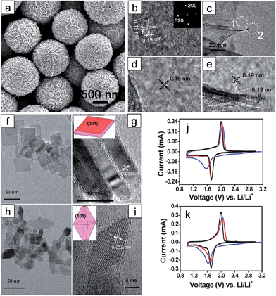 | ||
| Fig. 1 (a) SEM image of the as-synthesized TiO2 NSHSs. (b) HR-TEM image of an ultrathin TiO2 nanosheet (NS) showing two sets of perpendicular lattice fringes with a spacing of 0.19 nm. The interfringe spacing of 0.19 nm corresponds to anatase (020) and (200) planes (inset: FFT pattern indexed to the [001] zone). (c) TEM image around the edge of a TiO2 NS sphere. ((d) and (e)) HRTEM images of regions 1 and 2 marked with white dotted circles in (c), respectively. ((f) and (g)) TEM images of the anatase TiO2 with dominant {001} facets ((h) and (i)) TEM images of the anatase TiO2 with dominant {101} facets. Insets in (g) and (i) describe the geometrical models of the anatase single crystals. ((j) and (k)) Cyclic voltammograms of anatase TiO2 with dominant {001} and {101} facets at a scan rate of 0.1 mV−1, respectively (blue: 1st cycle; red: 2nd cycle; black: 5th cycle). Reprinted with permission from ref. 48 (Copyright 2010, American Chemical Society) and ref. 61 (Copyright 2010, Royal Society of Chemistry). | ||
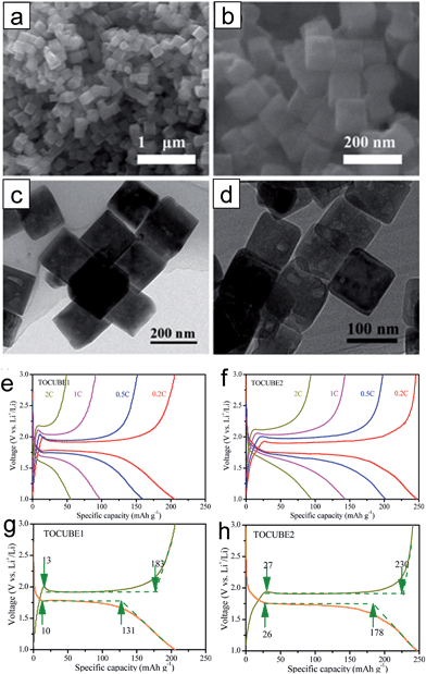 | ||
| Fig. 2 ((a) and (c)) SEM and TEM images of TOCUBE1. ((b) and (d)) SEM and TEM images of TOCUBE2. ((e) and (f)) The rate capabilities of TOCUBE1 and TOCUBE2 electrodes, respectively. ((g) and (h)) Voltage profiles of TOCUBE1 and TOCUBE2 electrodes, respectively. Reprinted with permission from ref. 62 (Copyright 2015, American Chemical Society). | ||
2.2 Doping
Doping with metallic ions is an effective strategy to engineer the semiconducting material to improve the electronic conductivity. The enhancement of TiO2 in electronic conductivity by doping with aliovalent ions is mainly attributed to the increased concentration of the electronic charge carriers. Substituting Ti4+ with an aliovalent dopant generates extra charge carriers.67 Various dopant materials such as N, Sn, B, F and Nb have been introduced into TiO2 to improve its electrical conductivity.20,21,23,68–77 An increased lithium storage capacity was observed in the doped active material, which might be attributed to the reaction of dopants with Li ions. It was reported that the substitutional doping of foreign atoms into TiO2 could induce the slight modification of the TiO2 lattice and change in its structural properties, which is desirable for the enhancement of lithium mass transport.21Mesostructured Nb-doped TiO2 nanoparticles76 and Nb-doped TiO2 nanofibers77 were explored as anode materials. Mesostructured Nb-doped TiO2 nanoparticles were prepared by using the amphiphilic block-copolymer KLE22 and Nb(OC2H5)5 as a template and Nb dopant precursor, respectively (Fig. 3(a)). The substitutional doping of TiO2 with niobium increases the electrical conductivity of TiO2. The ionic radius of Nb5+ (0.64 Å) is comparable with that of Ti4+ (0.605 Å) in an octahedral environment. Mesostructured Nb-doped TiO2 nanoparticles with 6.5% Nb content exhibited an electronic conductivity of 2.86 × 10⁻⁶ S cm−1, which are more than two orders of magnitude higher compared to that of undoped TiO2 with mesoporosity (conductivity 2.38 × 10⁻⁸ S cm−1). The mesostructured Nb-doped TiO2 nanoparticle electrode delivers a reversible capacity of 167 mA h g−1 at a constant current of ∼C/6 with a voltage window between 1 V and 3.1 V. The mesostructured Nb-doped TiO2 nanoparticle electrode shows rate capabilities of 160.3, 142.4, 124.6, 108.2, and 89.8 mA h g−1 at C/6, 0.25C, 0.5C, 1.0C, and 2.0C, respectively (Fig. 3(b)). Fehse et al. synthesized Nb-doped TiO2 nanofibers (Nb content of 8.1 ± 0.2 at%) with an average diameter of 51 ± 19 nm using niobium ethoxide as a dopant precursor via an electrospinning method (Fig. 3(d)).77 The Nb-doped TiO2 nanofiber electrode exhibits increased reversible capacity and improved rate capability compared to those of pristine TiO2 nanofiber electrode, which is attributed to the enhanced electronic conductivity related to the change in the Fermi level position and the reduced diffusion path originated from the decreased crystal size (Fig. 3(c) and (e)).
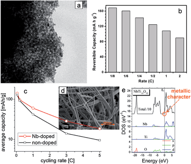 | ||
| Fig. 3 (a) TEM image of the mesoporous Nb-doped TiO2. (b) The rate capability of the mesoporous Nb-doped TiO2 electrode. (c) The rate capabilities of pristine and Nb-doped electrospun TiO2 nanofiber electrodes. (d) SEM of Nb-doped electrospun TiO2 nanofibers. (e) Calculated partial densities of states of NbTi15O32 (≈6 at%). The origin of energy is taken at the Fermi level (dotted line). Reprinted with permission from ref. 76 (Copyright 2010, American Chemical Society) and ref. 77 (Copyright 2013, American Chemical Society). | ||
Nitrogen doping into substitutional sites of TiO2 is a facile and efficient way to improve the electronic conductivity. The uniform distribution of Nsub in TiO2 is crucial for narrowing the bandgap by elevating the valence band maximum, leading to the improvement in the electronic conductivity.78–80 Zhang et al. studied the electrochemical kinetic properties of the N-doped TiO2 nanoparticles by a galvanostatic intermittent titration technique (GITT) and electrochemical impedance spectroscopy.21 N-doped TiO2 nanoparticles were synthesized by a solvothermal method followed by heat treatment at 550 °C under an NH3 atmosphere. N-doped TiO2 exhibits slightly expanded crystal lattice (a = 3.7905 Å, b = 3.7905 Å, c = 9.5331 Å, and V = 136.97 Å3) compared to that for the pristine TiO2 (a = 3.7883 Å, b = 3.7883 Å, c = 9.5233 Å, and V = 136.67 Å3), which might be attributed to the larger N3− anion (r = 1.46 Å) than O2− (r = 1.36 Å).81 X-ray photoelectron spectroscopy results show that the surface of the N-doped TiO2 was dominated by interstitial N atoms, while interstitial and substitutional N coexisted in the bulk (Fig. 4(a)). Pristine N-doped TiO2 shows a single N 1s peak at 400.0 eV, corresponding to the interstitial N anion in TiO2 with an O–Ti–N bonding.82 After surface etching with Ar for 360 s, the peak corresponding to O–Ti–N bonding decreases while a peak at 396.8 eV was newly generated, which is assigned to the Ti–N bonding in TiN by substituting the O atom with the N atom.83,84 (Fig. 4(b) and (c)) present the chemical diffusion coefficient of Li+ (DLi) for the pristine TiO2 and N-doped TiO2 electrodes as a function of Li+ content. Both electrodes show similar DLi variation behavior during discharging. The N-doped TiO2 electrode has DLi of 2.14 × 10⁻¹¹ cm2 s−1 in the voltage plateau region, which is 13 times higher than that of pristine TiO2 (1.65 × 10⁻¹² cm2 s−1) N doping significantly improves the electrochemical kinetic properties of TiO2, leading to the improvement in the specific capacity and rate capability (Fig. 4(d)). Ventosa et al. reported that nitrogen and hydrogen treatments on anatase TiO2 crystals produce similar effects on the electrochemical properties, but the creation of oxygen vacancies upon ammonia annealing plays a major role in the electrochemical performance.85 However, the changes in the atomic structures and electronic structures of anatase TiO2 induced by nitrogen and hydrogen doping need to be further understood. Especially, since the first reports of electrochemical properties of anatase TiO2 by nitrogen doping,80 the doping of nitrogen has been believed to be the substitution to oxygen-site. However, there exist huge variations in the band gap and electrochemical properties of nitrogen-doped anatase TiO2, largely depending on the synthesis conditions.80,86 Therefore, further theoretical studies on this topic are necessary for clear understanding on the atomic structures and the effects on electrical properties.
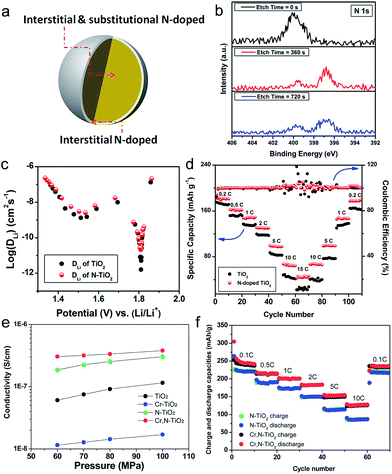 | ||
| Fig. 4 (a) Schematic illustration of N-doped TiO2. The surface of N-doped TiO2 is dominated by interstitial N, while interstitial and substitutional N coexist in the bulk. (b) XPS spectrum of N 1s N-doped TiO2 as a function of etching time. (c) DLi values of the TiO2 and N-doped TiO2 as a function of Li+ content. (d) Rate capabilities of the TiO2 and N-doped TiO2 electrodes. (e) Electrical conductivities of TiO2, N-doped TiO2, Cr-doped TiO2 and Cr, N-codoped TiO2 mesoporous microspheres under different pressures. (f) The rate capabilities of the N-doped TiO2, and Cr, N-codoped TiO2 mesoporous microsphere electrodes. Reprinted with permission from ref. 21 (Copyright 2014, American Chemical Society). | ||
The limited solubility of dopants for substitutional doping of TiO2 could prevent the effect of an increase of mobile charge carriers. Furthermore, dopants located in undesirable interstitial sites are not able to provide additional mobile charge carriers.87 Co-doping, C–N, N–S, F–N and Cr–N doping, has been also introduced into TiO2 to overcome this problem.88–91 Bi et al. reported on the use of Cr, N-codoped TiO2 mesoporous microspheres synthesized by a surfactant-free hydrothermal reaction followed by annealing under an NH3 atmosphere.88 The micrometer-sized particles composed of agglomerated crystal grains of 20 nm have an average diameter of 1.5 μm and uniform mesopores of 14 nm. The Cr, N-codoped TiO2 microsphere electrode shows an improved electronic conductivity and Li diffusion coefficient compared to pristine TiO2 and single elemental doped TiO2 microspheres. As shown in Fig. 4(e), the Cr, N-codoped TiO2 microspheres exhibited much higher electronic conductivity (3.05 × 10⁻⁷ S cm−1) than N-doped TiO2 (1.8 × 10⁻⁷ S cm−1) and Cr-doped TiO2 (1.22 × 10⁻⁸ S cm−1). Based on the Randles–Sevcik equation,92 the Cr, N-codoped TiO2 exhibits around three times higher Li diffusion coefficients (2.45 × 10⁻¹⁰ and 6.702 × 10⁻¹⁰ cm2 s−1 for insertion and extraction, respectively) compared to that of N-doped TiO2 (6.09 × 10⁻¹¹ and 2.37 × 10⁻¹⁰ cm2 s−1 for insertion and extraction, respectively) at room temperature. As shown in Fig. 4(f), the Cr, N-codoped TiO2 electrode shows enhanced rate capability at various C-rates (200, 153, 125 mA h g−1 at 1C, 5C and 10C, respectively) compared to the N-doped TiO2 electrode, which is attributed to both improved electronic conductivity and Li ion coefficient.
2.3 Surface treatment
Various surface treatment strategies, such as thermal nitridation, hydrogen reduction, vacuum treatment and metal coating, have been proposed to enhance the electrochemical properties of TiO2 based electrodes. Thermal nitridation of TiO2 in an NH3 atmosphere produces a conducting TiOxNy layer on the TiO2 surface. Han et al. reported nitridated TiO2 hollow nanofibers synthesized using dual-nozzle electrospinning and subsequent thermal nitridation.12 The hollow geometry and highly conducting TiOxNy shell layer enables a reduction of lithium ion transport length and a high electronic conductivity along the surface, respectively, both of which led to favorable kinetics. An amorphous TiOxNy layer was formed on the surface of TiO2 hollow fibers after the thermal nitridation. The nitridated TiO2 hollow nanofiber electrode exhibits much higher specific capacity (157 mA h g−1) and initial columbic efficiency (86.8%) than those of the pristine TiO2 hollow nanofiber (146. mA h g−1, 77.1%). Furthermore, it shows excellent rate capability (Fig. 5(a)). These improvements are attributed to hollow geometry and conducting TiOxNy layers formed on the TiO2 surface. The electrochemical properties of nitridated TiO2 nanoparticles have been evaluated as a function of the nitridation time and temperature.93 Although the uniform and homogeneous formation of the TiOxNy film on the TiO2 surface could improve its electronic conductivity, a thick TiOxNy layer could reduce the specific capacity and degrade the Li ion transport properties as TiN is an electrochemically inactive phase with lithium. Therefore, it is necessary for the optimization of nitridation processing condition for the balanced Li ion/electron transport properties. Samiee et al. reported that a lower nitridation temperature ranging from 450 to 500 °C is desirable for the improvement in electrochemical properties as a thinner and less-disordered TiOxNy layer enables the enhancement in electronic conductivity without degradation of lithium ion transport properties (Fig. 5(b)).93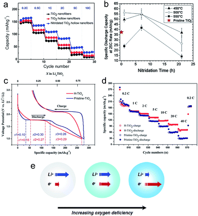 | ||
| Fig. 5 (a) The rate capabilities of the TiO2 nanofibers, TiO2 hollow nanofibers, and nitridated TiO2 hollow nanofibers. (b) The specific discharge capacities of TiO2 electrodes as a function of the nitridation annealing time and temperature at the 25C discharge rate. (c) The initial galvanostatic charging/discharging profiles for pristine- and hydrogenated TiO2 (H-TiO2) electrodes. (d) The rate performance of pristine- and H-TiO2 electrodes. (e) Schematic illustration for the variation of the Li+/e− transport properties as a function of oxygen deficiency. Reprinted with permission from ref. 12, 22, 93 and 98. | ||
Hydrogenated TiO2 has received significant attention as a method to improve the rate capability.22,24,94–98 Hydrogen reduction generates a disordered surface layer containing Ti3+ species and oxygen vacancy on the TiO2 surface, which improves the electric conductivity.24,98 Yan et al. reported that hydrogenated anatase TiO2 nanoparticles prepared via a H2 plasma treatment exhibits fast lithium storage performance.98 The hydrogenated TiO2 nanoparticle electrode exhibits a shorter voltage plateau at 1.7 V and a longer sloping region between 1.7 and 1.0 V compared to those of the pristine TiO2 electrode (Fig. 5(c) and (d)). The sloping region originates from lithium ion storage from faradaic reactions at the surface, which is much faster than bulk insertion at a high rate.16,99–101 The disordered surface layer generated by hydrogen reduction induces a higher surface pseudocapacitive lithium storage and enhanced electronic conductivity than pristine TiO2, leading to improved kinetics and improved rate capability (Fig. 5(d)). Eom et al. synthesized vertically aligned black TiO2 nanotube array on the TiH1.5 substrate via a thermal conversion treatment of amorphous TiO2 nanotube array under a hydrogen atmosphere.102 The black TiO2 nanotube is composed of a mixture of amorphous and anatase phases. The TiH1.5 phase on the Ti substrate enables a fast electron insertion and extraction into/from the black TiO2 nanotubes. The black TiO2 nanotube array shows stable cycling performance and excellent rate capability. The discharge capacity of black TiO2−x nanotube maintained nearly 72% of its discharge capacity at a current density of 0.1 mA cm−2. The improved electrochemical properties are attributed to the enhanced electronic conductivity, originating from the reduced Ti3+ ions and oxygen vacancies, and the facile reaction with Li+ ions via the amorphous phase.
Although the hydrogen reduction is a promising method to improve the electrochemical properties of TiO2, the processing condition should be optimized to achieve well-balanced electronic/ionic transport properties. Shin et al. prepared the oxygen-deficient TiO2−δ nanoparticles as a function of hydrogen treatment time.22 Both the electronic conductivity and chemical diffusion coefficient of the Li ion strongly depend on the hydrogen treatment time (Fig. 5(e)). The TiO2−δ nanoparticle electrode prepared by hydrogen thermal treatment for 1 hour showed much improved electrochemical properties including the specific capacity, cycle retention and rate capability due to the well-balanced improvement in electronic/ionic transport properties compared to those of the TiO2−δ nanoparticle electrode prepared by hydrogen thermal treatment for 7 hours. The degradation in the electrochemical properties of the TiO2−δ nanoparticle electrode prepared under severe reduction is attributed to the depression of free Li+ concentration caused by association with excess electrons. Similar to hydrogen reduction, a disordered amorphous shell layer (2–4 nm thick) containing the oxygen vacancies and Ti3+ species could also be formed on the surface of the crystalline TiO2 nanocrystal with the use of vacuum treatment.103 The vacuum-treated TiO2 nanocrystal electrode exhibits the improved rate capability, smaller polarization during cycling and longer charge/discharge plateaus compared to those of the pristine TiO2 nanocrystal electrode, which is attributed to the increased electronic conductivity originating from oxygen vacancies and a facile Li ion transport.
Xia et al. proposed the oxygen-vacancy adequate amorphous TiO2−x shell layer coated crystalline and stoichiometric TiO2 (SATNCs) via a sol–gel method followed by a high temperature vacuum process.104 In the given microstructure, a built-in electric field (BIEF) across the interface between the crystalline core and amorphized layer could be generated, which enables facile Li ion transport during both insertion/extraction processes. In the lithium insertion process, the BIEF is applied from the outer layer to the core, resulting in the fast Li+ diffusion (Fig. 6(a)). In the lithium insertion process, the direction of BIEF is inverted, facilitating Li ion transport from the core to the shell (Fig. 6(a)). Although the BIEF is not favored for electron movement, the overall charge transport resistance could be reduced as the electron diffusion coefficient is much higher compared to that of Li ion. The SATNC has an average diameter ranging from 8 to 15 nm and a 1–2 nm thick amorphous shell layer. Electrochemical impedance spectroscopy results indicate that the BIEF lowered the charge transport/diffusion resistance in the bulk. The SATNCs electrode delivered the specific capacities of 175, 164 and 120 mA h g−1 at 1C, 10C and 50C, which are 11, 56, and 243% higher compared to those of the pristine TiO2 nanocrystal electrode, respectively (Fig. 6(b)). Much longer charge/discharge voltage plateaus were observed in the SATNC electrode compared to that of the pristine TiO2 nanocrystal electrode at the charge rate of 20C, which is crucial for power management and constant voltage output (Fig. 6(c)). These improvements are attributed to the low lithium-ion transport resistance and the large charge diffusion depth within the nanocrystal resulting from both the BIEF effect and the amorphous shell layer with oxygen vacancies.
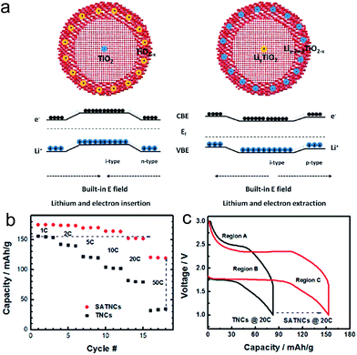 | ||
| Fig. 6 (a) Illustration of the charge transport under the BIEF during discharge (left) and charge (right) processes. (b) Rate capability of the TiO2 nanocrystals (TNCs) and the SATNCs electrodes. The charge rate was changed from 1C to 50C while the discharge rate was maintained at 1C. (c) Galvanostatic charge/discharge profiles for TNC and SATNC electrodes at charge rates of 20C. Reprinted with permission from ref. 104 (Copyright 2013, American Chemical Society). | ||
2.4 Electronic resistance at the interface
As introduced above, various approaches have been explored to improve the rate capability by enhancing both the electronic conductivity and the lithium kinetics in the TiO2 active material or the composite electrode film of the TiO2 active material/conducting agent/binder. Generally, the contact between the metal and the semiconducting material has been carefully controlled in the electronic devices as inappropriate contact at the interface between the materials could induce poor performances of the electronic devices. Similar to the electronic device, the electronic contact at the interface between the current collector and the active material in the electrode should be carefully considered for the improvement in the electronic conductivity of the overall cell. A huge energy barrier for electron injection or extraction between the current collector and the electrode could result in a poor electronic conductivity of the overall electrode system.Han et al. carried out a systematic study of the contact resistance effect on the rate capability of a TiO2 based electrode using a conventional composite electrode of a randomly oriented TiO2 nanotube/conducting agent/binder, directly grown sealed TiO2 nanotube arrays, and unsealed TiO2 nanotube arrays on the current collector in order to provide underlying design guideline on the electrode configuration design for high power density (Fig. 7(a)).33 The conventional composite electrode has physical and/or chemical contact with a current collector through the binder, which induces a high contact resistance at the composite electrode/current collector interface. The vertically aligned, sealed TiO2 nanotube array electrode has a direct chemical bonding with the current collector, reducing the electronic resistance at the interface. The unsealed TiO2 nanotube array has more enhanced Li ion kinetics through the increase in the Li ion flux at the interface between the active material and the electrolyte, enabling the study on the influence of kinetics associated with the lithium ion and the electronic resistance at the interface.12 The discharge capacity of the conventional electrode increases with the amount of conducting agent. As shown in Fig. 7(b), the rate capability was also improved by increasing the amount of carbon conducting agent in the conventional composite electrodes, which is attributed to the enhancement of electronic conductivity in the conventional composite electrodes containing a higher amount of conducting agent. On the other hand, much improved rate capabilities were observed in the sealed and unsealed TiO2 nanotube array electrodes even in the absence of the conducting agent compared to the conventional composite electrode with 30 wt% carbon conducting agent. The improved Li ion related kinetics caused by the hollow geometry result in better rate capability in the unsealed TiO2 nanotube array electrode than the sealed TiO2 nanotube array. These results strongly indicate that the contact resistance at the interface between the metal current collector and the electrode plays an important role in the improvement in the rate capability compared to the enhancement of electronic conductivity in the composite electrode. However, this conclusion is only valid for a very thin electrode (in this report, the thickness of electrodes are 2 μm) as the electronic resistance of the TiO2 nanotube electrode significantly increases with the length of the TiO2 nanotube. TiO2 sol–gel nanoglues were applied to the TiO2 nanofiber electrode to increase the adhesion strength between nanofibers and the current collector without polymeric binders, leading to improved cycle performance and coulombic efficiency (Fig. 7(c)).105
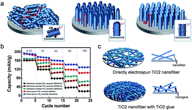 | ||
| Fig. 7 (a) Schematic illustration of randomly oriented TiO2 nanotubes, directly grown sealed TiO2 nanotube arrays, and unsealed TiO2 nanotube arrays on the current collector. (b) Rate capabilities of sealed and unsealed TiO2 nanotube electrodes directly grown on a current collector and randomly oriented TiO2 nanotube electrodes with various amounts of carbon black (10 to 30 wt%) at different current densities. (c) Schematic illustration of electrospun TiO2 nanofibers and TiO2 nanofibers with TiO2 nanoglue. TiO2 nanoglue fills the spaces between TiO2 nanofibers and the current collector, leading to the increase of the contact area of electrode materials on the current collector. Reprinted with permission from ref. 33 (Copyright 2012, American Chemical Society) and ref. 105 (Copyright 2013, Royal Society of Chemistry). | ||
The electronic resistance of the overall electrode system can be described by the sum of the electronic resistance at the interface between the metal current collector and active material and the electronic resistance of the electrode. Although the high rate capability of the TiO2 nanotubes electrode could be achieved by the direct electric contact between the current collector and the TiO2 active material, there exists a limitation in the increase of areal capacity (mA h cm−2) due to the significant increase in the electronic resistance of the TiO2 nanotube (TiO2 NT) with its length (Fig. 8(a)).33 Song et al. proposed TiO2 nanotubes in a branched tree arrangement on carbon nanofibers (TiO2 NT–CNF) to address this issue. Carbon nanofibers directly grown on the current collector provides an interconnected network for ballistic electron transport and reduces the contact resistance between the branched TiO2 nanotubes and current collector.106 (Fig. 8(a) and (b)) shows cross-sectional SEM images of the TiO2 NT with different lengths and TiO2 NT–CNF. Although the areal capacities of the vertically aligned TiO2 nanotube array electrodes increase with its length (0.5 μm – 0.013 mA h cm−2; 4 μm – 0.088 mA h cm−2, and 8 μm – 0.172 mA h cm−2), their rate capabilities were degraded with the increase of the length due to the increased electronic resistance of TiO2 nanotube electrodes inside. The TiO2 NT–CNF with 4.5 μm height exhibits excellent rate capability, which is comparable with that of the vertically aligned TiO2 nanotube electrode with a length of 0.5 μm (Fig. 8(c)). Furthermore, the TiO2 NT–CNF electrode has an areal capacity of 0.114 mA h cm−2, which is slightly lower than that of the vertically aligned TiO2 nanotube electrode with a length of 8 μm. The reduction of electronic resistances at both the contact resistance at the interface between the metal current collector and TiO2 material and the short electron path in TiO2 is crucial to achieve high power and energy densities.
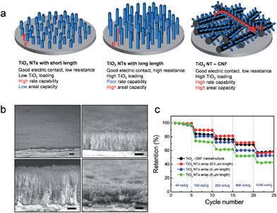 | ||
| Fig. 8 (a) Schematic illustration of the TiO2 nanotube (TiO2 NT) array with short length, TiO2 nanotube array with long length, and TiO2 NT–CNF on the current collector. (b) Cross-sectional SEM images of the TiO2 NT arrays with a length of 0.5 μm, 4 μm, and 8 μm, and the TiO2 NT–CNF nanostructure on the metal current collector. (c) The rate capabilities of the TiO2 NT arrays with a different length and the TiO2 NT–CNF nanostructured electrodes. Reprinted with permission from ref. 106 (Copyright 2014, Springer). | ||
3. TiO2 as a supplementary material for Li batteries
3.1 TiO2 in Li–S batteries
Among various next generation LIBs, lithium–sulfur (Li–S) batteries are one of the most promising candidates due to their large theoretical capacity of 1673 mA h g−1, and the natural abundance/low cost of sulfur.107–109 Despite these advantages, several inherent challenges of sulfur cathodes limit their practical use. One of the well-known issues is the dissolution of intermediate polysulfides (Li2Sn, 4 < n < 8) during the charge/discharge process into the organic electrolyte, resulting in low coulombic efficiencies and fast capacity fading.110,111 Furthermore, low electronic conductivities of both the sulfur and the lithium sulfides prevent the full utilization of active materials as well as greatly limit the rate capability.38,112,113 The large volumetric expansion (∼80%) associated with lithium also results in poor cycle performance.38 It was demonstrated that TiO2 could improve the electrochemical properties of Li–S batteries due to its unique physicochemical properties and a facile engineering in composition and morphology.36,114–119 She et al. proposed sulfur–TiO2 yolk–shell nanoparticles with internal void space as a cathode material for Li–S batteries.38 The internal void space (38%) in the yolk–shell nanoparticles enables the accommodation of the large volumetric expansion of sulfur during lithiation and the mesoporous TiO2 shell (average pore diameter of 3 nm) effectively suppresses the polysulphide dissolution. Furthermore, the hydrophilic Ti–O groups and surface hydroxyl groups in TiO2 could bind favorably with polysulphide anions, resulting in further suppression of the polysulphide dissolution.119–121Fig. 9(a) and (b) show the synthesis process of the sulfur–TiO2 yolk–shell nanoparticle and its TEM image. The sulfur nanoparticles are coated with amorphous TiO2 shells using a sol–gel method, followed by partial dissolution of sulfur in an isopropanol/toluene mixture solvent for the partial dissolution of sulfur and consequential generation of free space within the particle. The average nanoparticle size and TiO2 shell thickness are 800 and 15 nm, respectively. The sulfur–TiO2 yolk–shell nanoparticles exhibited a robust morphological change associated with lithium without fracture of the TiO2 shell due to the ability of accommodating the volume expansion of sulfur. The yolk–shell nanoparticle electrode delivered an initial specific capacity of 1030 mA h g−1 at 0.5C and stable cycle retention of 81% at the end of 500 cycles (Fig. 9(c)).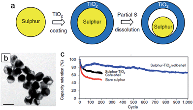 | ||
| Fig. 9 (a) Schematic of the synthetic process that involves coating of sulphur nanoparticles with TiO2 to form sulphur–TiO2 core–shell nanostructures, followed by partial dissolution of sulphur. (b) TEM image of sulphur–TiO2 yolk–shell nanostructures. Scale bar, 1 μm. (c) Capacity retention of bare sulphur and sulphur–TiO2 core–shell nanoparticles, sulphur–TiO2 yolk–shell nanostructure electrodes at 0.5C. Reprinted with permission from ref. 38 (Copyright 2013, Nature Publishing Group). | ||
The hydrogen reduced TiO2 inverse opal structure has been explored as a sulfur reservoir to improve the electrical conductivity, physical sulfur encapsulation and polysulfide binding properties.37 Heat treatment of TiO2 in a reducing gas atmosphere could generate oxygen vacancies and Ti3+ species, resulting in the enhancement of electrical conductivity of TiO2. Furthermore, the oxygen vacancies may promote the interaction between TiO2 and sulfur (S–Ti–O), which enhance polysulfide adsorption on the TiO2 surface.121 3D frameworks enable the improvement in kinetics associated with the Li ion and electron as well as the physical confinement of polysulfides. For the preparation of the TiO2 inverse opal structure, polystyrene (PS) colloidal sphere dispersed in aqueous suspension was deposited onto the aluminum foil disc as a template. A 30 nm-thick amorphous TiO2 layer was deposited on the surface of hexagonally close-packed PS spheres through the low temperature atomic layer deposition method, followed by the removal of PS template and hydrogen reduction. Fig. 10(a) shows the SEM image of the S incorporated reduced TiO2 inverse opal structure. The hydrogen reduced TiO2 inverse opal-sulfur nanocomposite electrode delivers an initial specific capacity of ∼1100 mA h g−1 and a reversible capacity of ∼890 mA h g−1 after 200 cycles with coulombic efficiencies of 99.5% at a C/5 rate (Fig. 10(b) and (d)). The hydrogen reduced TiO2 inverse opal-sulfur nanocomposite electrode exhibited little change in morphology before and after lithiation. It maintained its original geometry and structurally intact TiO2 coating after 100 cycles, which is attributed to the robustness of the electrode resulting from (i) the facile accommodation of the volumetric change of sulfur using the empty space inside the TiO2−x inverse opal structure, (ii) the electrochemical inactivity of the TiO2−x associated with lithium during the charging/discharging and (iii) high mechanical strength of TiO2.
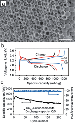 | ||
| Fig. 10 (a) Cross-sectional SEM image of the reduced TiO2 inverse opal structure after sulfur infusion. Scale bars are 2 μm. (b) Charge/discharge profiles at different current rates (1C = 1675 mA h g−1). (c) Cycle performance (black curve) and coulombic efficiency (blue curve) of TiO2−x/sulfur composite cathode at a current rate of C/5. Reprinted with permission from ref. 37 (Copyright 2014, American Chemical Society). | ||
The lightweight graphene/TiO2 composite film was introduced as an interlayer placed in between the sulfur cathode and the separator to improve the electrochemical properties by intercepting the migrating polysulfides and fully using the active material (Fig. 11(a)).36 An electrostatic attraction (S–Ti–O) promotes the interaction between TiO2 and S, leading to the chemical interception of migrating polysulfides.37,122 The graphene serves to physically intercept the migrating polysulfides. For the preparation of the interlayer slurry, mesoporous anatase TiO2 (3 wt% in the hybrid structure) dispersed in N-methyl-2-pyrrolidone (NMP) and graphene powder are mixed. The 3 μm-thick graphene/TiO2 composite film is coated on the 30 μm-thick porous carbon nanotube (PCNT)–S cathode (PCNTs–S@G/3%T) as an interlayer (Fig. 11(b)). The PCNT–S@G/3%T sample exhibited the lowest voltage hysteresis compared to those of PCNT–S (without interlayer) and PCNT–S@G (only graphene interlayer without TiO2) samples, which indicates a low resistance and facile electrochemical redox reaction in the PCNT–S@G/3%T sample. With respect to electrochemical properties, the PCNT–S@G/3%T sample delivers a reversible capacity of ∼1050 mA h g−1 in the first cycle and a reversible capacity of ∼1040 mA h g−1 over 300 cycles at 0.5C (Fig. 11(c)). The stable cycle performance of the PCNT–S@G/3%T sample is attributed to the physical and chemical trap of polysulfides from the graphene and TiO2, respectively, in the graphene/TiO2 interlayer. Zhou et al. prepared a free-standing TiO2 nanowire/graphene hybrid membrane for Li/dissolved polysulfide batteries.123 The hierarchical composite structure could be achieved by the introduction of TiO2 nanowires. In addition, the TiO2 nanowires enable the strong chemical binding with lithium polysulfides as well as facile polysulfide reduction and oxidation due to their strong catalytic effect, which leads to the improvement in the cycle performance and a fast redox reaction kinetics.
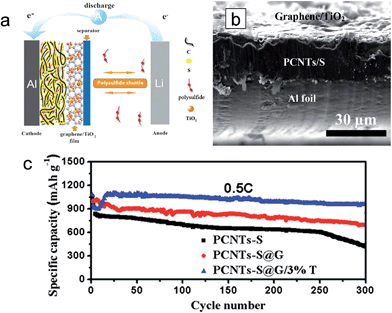 | ||
| Fig. 11 (a) Schematic of electrode configuration for Li–S battery with a graphene/TiO2 coating film. (b) Cross-sectional SEM images of the cathode with a graphene/TiO2 coating film. (c) Cycling stability of PCNTs–S, PCNTs–S@G, PCNTs–S@G/3%T cathodes at 0.5C, the current density of 0.86 mA cm−2. Reprinted with permission from ref. 36 (Copyright 2015, Wiley). | ||
3.2 TiO2 in cathode materials for Li ion batteries
TiO2 has also been also employed as a coating material to improve the electrochemical properties of various cathode materials including LiCoO2, LiFePO4, and LiMn2O4.45,46,124–132 TiO2 coating on cathode materials results in improved and/or degraded electrochemical properties depending on the materials and evaluation conditions. LiCoO2 has been widely used in commercial Li-ion batteries due to its typical stable layered structure. However, more than half of the Li extraction in LiCoO2 (LixCoO2, x < 0.5; >4.2 V vs. Li+/Li) induces a structural change from the original hexagonal phase to a monoclinic phase due to dissolution of Co4+, which limits a reversible amount of lithium x in Li1−xCoO2 up to 0.5 corresponding to a discharge capacity of ∼140 mA h g−1.124 The effect of TiO2 coating on the electrochemical properties of LiCoO2, related to the structural stability and Co4+ dissolution, was studied. Mainly two methods were adopted for the TiO2 coating on the surface of LiCoO2; (1) the sol–gel method46 and (2) the atomic layer deposition (ALD) technique.45 Interestingly, different results were reported depending on the TiO2 coating method. As shown in Fig. 12(a), the TiO2 coated LiCoO2 electrode, prepared by a sol–gel method, exhibits improved cycle retention compared to that of the bare LiCoO2 electrode, which is attributed to the suppression of the lattice-constant changes during electrochemical cycling by a high-fracture-toughness of the TiO2 coating layer. On the other hand, the TiO2 coated LiCoO2 electrode, prepared by ALD, shows an improvement in cycle retention only at the prolonged cycle numbers (Fig. 12(b)).45 In the initial stage of cycling, the TiO2 coating layer participates in the redox reaction as electrons and holes have enough energy to flow into the TiO2 due to its small band gap energy, which may allow Co4+ dissolution and the attack of HF in the electrolyte by the decomposition of the TiO2 coating layer. However, after prolonged cycles, the energy barrier between the valence band maximum of LiCoO2 and TiO2 could be gradually increased due to the electron loss of TiO2 in each cycle, finally stopping the access of holes. Therefore, the TiO2 coated LiCoO2 electrode shows enhanced cycle performance after prolonged cycles. Further study is needed to clarify different electrochemical properties of the TiO2 coated LiCoO2 associated with the coating method.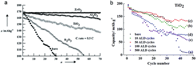 | ||
| Fig. 12 (a) The cycle performances for ZrO2-, Al2O3-, TiO2-, B2O3-coated, and bare LiCoO2. The cells were initially cycled at the rate of 0.1C, followed by 0.5C rate between 4.4 and 2.75 V at 21 °C (n: cycle number, x: discharge capacity). (b) Cycle performance of the TiO2-coated and bare LiCoO2 electrodes as a function of ALD cycle number on the LiCoO2 electrode. Reprinted with permission from ref. 46 (Copyright 2001, Wiley) and ref. 45 (Copyright 2012, American Chemical Society). | ||
LiFePO4 proposed by Padhi et al. is a promising cathode material due to its high safety and theoretical capacity (170 mA h g−1).133 However, the Fe ion in the LiFePO4 is dissolved at high temperature and then subsequently deposited on the surface of the anode, which leads to a poor cyclability as the deposited Fe ion acts as a catalyst and promotes the formation of the solid/electrolyte interphase (SEI) layer.134 Chang et al. studied the cycle performance of TiO2 coated LiFePO4 at high temperature.126 TiO2 was coated on the surface of LiFePO4 by a sol–gel process. The TiO2 coated LiFePO4 electrode cycled against a Li metal as a counter electrode exhibited enhanced cycle retention (96% after 90 cycles) compared to that of uncoated LiFePO4/Li cell (90% after 90 cycles) under a voltage window between 2.5 and 4.3 V at 55 °C (Fig. 13(a)). On the other hand, when cycled against carbon as an anode, the uncoated LiFePO4/carbon cell showed better cyclability (71% after 90 cycles) than that of the TiO2 coated LiFePO4/carbon cell (61% after 90 cycles) under a voltage window between 2.5 and 3.65 V at 55 °C (Fig. 13(b)). These results indicate that the TiO2 coating is helpful to suppress the Fe ion dissolution from LiFePO4. However, TiO2 is unstable during cycling, which lead to the partial dissolution of Ti from TiO2 and the deposition of dissolved Ti on the surface of the carbon anode. Deposited Ti on the carbon anode accelerated the formation of the SEI layer, leading to fast capacity fading.
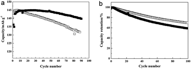 | ||
| Fig. 13 (a) Discharge capacity data for the LiFePO4 electrodes/Li cells. The cells were cycled at 55 °C at 1C rate between 2.5 and 4.3 V. (b) Cycle retention for the LiFePO4 electrode/carbon type of cells (filled: TiO2-coated LiFePO4; empty: uncoated-LFPO). Reprinted with permission from ref. 126 (Copyright 2008, Elsevier). | ||
Among various advanced cathode materials, layered lithium-rich oxides, xLi2MnO3·(1 − x)LiMO2 (M = Mn, Ni, and Co), are promising electrode materials owing to their high capacities (over 250 mA h g−1) and safety.132,135 However, these materials suffer from large initial irreversible capacity, poor cycle performance and the discharge voltage decay associated with the electrolyte decomposition and dissolution under a wide operating voltage (2.0–4.7 V). Zhang et al. prepared TiO2 (or Al2O3) coated Li1.2Mn0.54Ni0.13Co0.13O2 using ALD and studied its electrochemical behaviors at room temperature (25 °C) and 55 °C.132 The TiO2 coated Li1.2Mn0.54Ni0.13Co0.13O2 electrode exhibited slightly higher discharge capacity compared to that of the pristine sample, which is attributed to transformation of the TiO2 layer to LixTiO2 (lithiation of TiO2) during the discharge. While the TiO2 coated Li1.2Mn0.54Ni0.13Co0.13O2/Li metal cell presented improved cycle performance compared to that of the bare Li1.2Mn0.54Ni0.13Co0.13O2/Li metal cell at room temperature (Fig. 14(a)), no noticeable difference in the cycle retention is observed at 55 °C (Fig. 14(b)). This phenomenon is also observed in the cycling of graphite-cells. The TiO2 coating layer participates in the redox reaction associated with lithium, which leads to exacerbate the capacity fading due to catalysis reactions of the Ti3+ surface cation. For the successful utilization of TiO2 in the cathode, further study on structurally stabilizing TiO2 and composition engineering for the suppression of participating in the redox reaction is necessary.
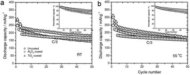 | ||
| Fig. 14 Cycling performance of the Li/Li1.2Ni0.13Mn0.54Co0.13O2 cells with Al2O3 and TiO2 ALD coatings at (a) room temperature and (b) 55 °C. Test procedure: cycle 1 at C/10 rate between 2.0 and 4.8 V for activation; cycle 2–3 is formation cycle at C/10 between 2.0 and 4.6 V; cycle 4–50 at C/3 between 2.0 and 4.6 V. The inset figures are normalized capacity retention at C/3 rate. Reprinted with permission from ref. 132 (Copyright 2013, Wiley). | ||
3.3 TiO2 as a mechanical support for the alloy-type anode material in lithium ion batteries
The demand for rechargeable lithium ion batteries with high energy densities has been increased to expand their application fields into electric vehicles (EVs), plug-in hybrid electric vehicles (PHEVs), and smart grid systems.136,137 The study on alternative electrode materials with high lithium storage capacity is crucial for the development of lithium ion batteries with high energy densities. Alloy type anode materials, such as Si, Ge, Sn, and transition metal oxides have attracted significant interest due to their large theoretical capacity.138,139–145 However, poor cycle performance of these alloy type anode materials caused by a large volume change associated with the Li ion limits its practical applications.138 As discussed previously, TiO2 exhibits excellent structural stability associated with lithium, which enables the utilization of TiO2 as a mechanical support against the pulverization of alloy type active materials to improve the cycle stability.Although Si is one of the most promising anode materials for lithium ion batteries due to its large theoretical capacity of ∼3500 mA h g−1 and a relatively low working potential (∼0.5 V vs. Li/Li+),146 its practical use has been limited by both the poor cycle performance and rate capability.140,141 Furthermore, it exhibited poor thermal stability including a severe exotherm in the range of 300–400 °C.147 Various strategies have been reported to improve the electrochemical properties of the Si based electrode by employing TiO2.147,148 Jeong et al. reported a core–shell structured Si nanoparticle@TiO2−x/carbon mesoporous microfiber composite as an anode material for silicon's safe and robust operation.148 Oxygen deficient TiO2−x acts as a mechanical support to prevent the pulverization of the Si nanoparticles upon repeated volume change during cycling, a fast electrical pathway as well as a physical/chemical interfacial barrier by suppressing the exothermic reaction between the lithiated Si phase and the electrolyte combined with its intrinsically stable thermal properties (Fig. 15(a)). The electrospun microfibers have an average diameter of ∼2 μm with a 200–300 nm thick TiO2−x/carbon shell. The core region was comprised of Si nanoparticles with a diameter of roughly 50 to 100 nm. After lithiation, the formation of LiTiO2 phase from rutile TiO2−x in the shell occurred at voltages low voltages of 0.005 V. This LiTiO2 phase still remains after full delithiation (up to 1 V) due to Li not being able to be extracted under 1.0 V. The composite microfiber delivers a charge and discharge capacity of 1710 and 1260 mA h g−1, respectively, corresponding to the initial coulombic efficiency of 74%. The low initial coulombic efficiency could be attributed to the irreversible trapping of Li in TiO2−x and SEI layer formation.149–152 As shown in Fig. 15(b), the composite microfiber electrode shows a stable cycle performance of 90% after 50 cycles at 0.2C and excellent rate capability (939 mA h g−1 at 12C), which is ascribed to the effective prevention of Si pulverization by the mechanically robust TiO2−x/C shell and enhanced electrical conductivity of formed LixTiO2 due to the existence of Ti3+.149,153 The composite nanofiber electrode exhibited a significantly reduced exotherm in the overall temperature range (4.2 kJ g−1) at 100% state of charge compared to those of graphite (5.7 kJ g−1) and Si nanoparticle (11.4 kJ g−1) electrodes, which is attributed to the hindrance of the intensive thermal reaction between the lithiated Si and the electrolyte.
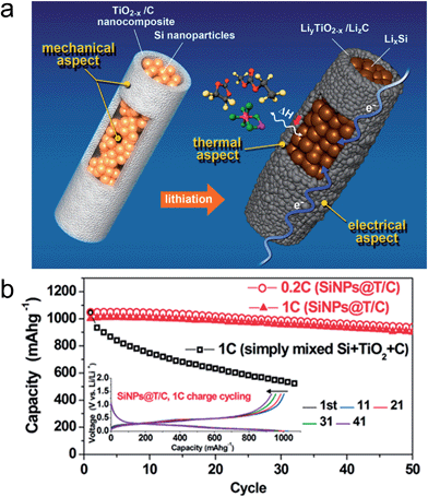 | ||
| Fig. 15 (a) Schematic illustration of a core–shell structured Si nanoparticle@TiO2−x/C mesoporous microfiber composite, which is mechanically, electrically, and thermally robust architecture. The molecules expressed with the ball and stick model indicate EMC, EC, and LiPF6 in the electrolyte solution (counterclockwise from top) and ΔH means an exothermic enthalpy in the reaction between LixSi and the electrolyte. (b) Capacity retention of the SiNPs@T/C electrode and the corresponding voltage profiles (inset). Reprinted with permission from ref. 148 (Copyright 2014, American Chemical Society). | ||
Although Ge has a lower gravimetric capacity (1600 mA h g−1) compared to Si, it exhibits excellent kinetics associated with both lithium ion and electron; two orders of magnitude higher lithium ion diffusivity and four orders of magnitude higher electronic conductivity than Si.142,154,155 However, it also suffers from poor cycle performance. Fang et al. proposed three-dimensional (3D) rutile TiO2@Ge core–shell nanorod arrays on carbon textiles to improve the cycling performance.156 TiO2 nanorods were first grown onto the carbon textiles via a hydrothermal method and a subsequent coating of the Ge layer using radio frequency (RF) magnetron sputtering (Fig. 16(a)). The TiO2@Ge core–shell nanorods have a length of 3–4 μm and a diameter of about 500–600 nm (Fig. 16(b)). In the voltage window 0.01–1.0 V, the TiO2@Ge core–shell nanorod electrode delivers the charge and discharge capacities of 1603.7 and 1397.1 mA h g−1 at a current density of 1 A g−1, respectively, corresponding to the initial coulombic efficiency of 87.11% (Fig. 16(c)). Rutile TiO2 transformed to a mixture of LiTiO2 and Li0.5TiO2 after the first lithiation. Robust cycle performance was observed for 200 cycles (83%) in the TiO2@Ge core–shell nanorod electrode (Fig. 16(d)).
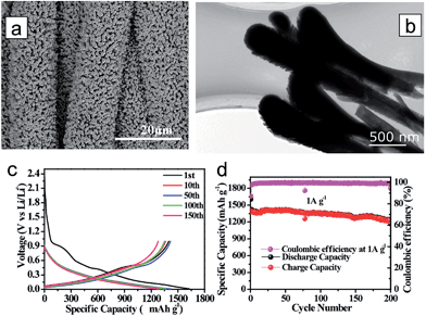 | ||
| Fig. 16 (a) TiO2@Ge nanorod arrays grown on carbon textiles. (b) Low-magnification TEM image of the TiO2@Ge nanorod. (c) Galvanostatic discharge/charge profiles of the TiO2@Ge nanorod arrays. (d) Cycling performance of TiO2@Ge nanorod arrays at a current density of 1 A g−1. Reprinted with permission from ref. 156 (Copyright 2015, Wiley). | ||
SnO2 is also gaining momentum as a potential anode material due to its abundance and high theoretical capacity (∼780 mA h g−1).144,145 SnO2 shows a fast capacity fading caused by the large volume expansion (300% change upon Li+ alloying). Ternary Sn–Ti–O based nanostructures have been intensively explored to overcome this problem.157 Park et al. proposed SnO2 encapsulated TiO2 hollow nanofibers (HNFs) to improve electrochemical performances.158 The mechanical robustness of the TiO2 shell and hollow inner space led to a confined volume expansion of the encapsulated SnO2 nanoparticles upon electrochemical alloying and dealloying with lithium, which leads to the improvement in cycle retention and reversible morphological changes (Fig. 17(a)). Furthermore, Sn metal particles formed from SnO2 decomposition after the first cycle could improve the rate capability via triggering the electron transport along 1D geometry of the fiber. The nanofibers have an inner diameter of ∼200 nm and outer shell thickness of ∼30 nm. The nanofiber electrode shows charge and discharge capacities of ∼802 mA h g−1 and ∼517 mA h g−1 at the first cycle in the voltage window of 0.01–3 V, respectively (Fig. 17(b)). It also exhibited stable cycle performance after 100 cycles and excellent rate capability (Fig. 17(c)). Guan et al. reported excellent cycle retention using the hollowed wire-in-tube nanostructure of SnO2-in-TiO2. Hollow geometry was achieved using the ZnO sacrificial film and the TiO2 shell layer was coated using ALD.159 Hollowed SnO2-in-TiO2 nanofibers exhibit stable cycle performance over 1000 cycles. TiO2 enables a stable surface protection and an effective accommodation of the volume change of inside SnO2 nanowires. TiO2 has been intensively employed as a mechanical support for alloy type anode materials. It is believed that engineering the composition and geometry of TiO2 and understanding the change in physicochemical properties in the low voltage region will further improve the electrochemical properties of alloy type anode materials combined with TiO2. Fu et al. reported porous hollow α-Fe2O3@TiO2 core–shell nanospheres, synthesized by a facile carbon-template method, as an anode material.160 Although α-Fe2O3 has a high theoretical capacity of 1007 mA h g−1, it also suffers from poor electrochemical properties due to the large volumetric change during cycling. The porous hollow α-Fe2O3@TiO2 core–shell nanosphere electrode exhibits improved specific capacity and cycle life, which is attributed to the facile accommodation of the volume change using the porous hollow geometry and the suppression of the pulverization and aggregation of α-Fe2O3 by the TiO2 shell layer.
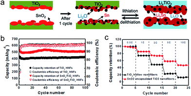 | ||
| Fig. 17 (a) Morphological changes during lithiation/delithiation of SnO2/TiO2 HNFs. (b) Cycle retentions and coulombic efficiencies for TiO2 and SnO2/TiO2 HNFs electrodes. (c) Rate capabilities of TiO2 and SnO2/TiO2 HNF electrodes at different discharge rates. Reprinted with permission from ref. 158 (Copyright 2012, Elsevier). | ||
3.4 TiO2 in Li–O2 batteries, gel electrolyte and membrane
Li–O2 batteries have been considered as a next generation energy storage system due to their higher energy density (∼3500 W h kg−1) and simple operation concept.109,161–163 However, poor electrochemical properties caused mainly by large polarization upon both the oxygen reduction reaction (ORR) and oxygen evolution reaction (OER) hinder their practical use.161,164,165 Of most importance, a large polarization during the OER and formation of the decomposition of the carbon cathode results in poor reversibility and decomposition of the electrolyte. TiO2 has been evaluated as a catalyst or cathode catalyst support to improve the electrochemical properties by improving the catalytic activity hindering the degradation caused by the decomposition of the carbon material and the electrolyte.39–41,166–168 Kang et al. prepared the anatase TiO2 nanofibers and rutile TiO2 nanofibers and evaluated their electrochemical properties as a cathode.41 The rutile TiO2 has better catalytic activity compared to the anatase TiO2, leading to the higher round-trip efficiency and lower polarization during the OER. Zhao et al. utilized the TiO2 nanotube array as a catalyst support.39 Improved stability of the tetraethylene glycol dimethyl ether (TEGDME) electrolyte on the TiO2 surface compared to that on the carbon surface in a wide discharge/charge voltage window was observed. The TiO2 nanotube array was also utilized as a RuO2 catalyst support. The porous morphology of TiO2 nanotubes provides a facile oxygen transport. Geng et al. proposed, based on the first-principles density functional theory (DFT) calculations, that TiO2 could be a promising reservoir for Li2O2 as the metallic properties of the Li2O2/TiO2 (110) interface and the formation of amorphized of Li2O2 with abundant grain boundaries caused by the large lattice mismatch at the Li2O2/TiO2 (110) interface could possibly lead to the formation of low-resistance Li2O2 thin films for enhanced electrochemical properties.40 It was demonstrated that very thin TiO2 layer (∼2 nm) coated TiC could facilitate Li2O2 oxidation with a greatly decreased polarization.166,168 RuO2 supported mesoporous TiO2 (RuO2/mTiO2) has been employed as a carbon-free cathode material for Li–O2 batteries.169 The TiO2 surface is stable against the oxygen radicals during cycling. The RuO2/mTiO2 cathode shows the capacity of 2000 mA h g−1 with a low charge potential of under 4 V. Further studies on engineering the polymorphism and composition of TiO2 could open up further possibilities for the improvement in electrochemical properties of Li–O2 batteries.TiO2 has been also employed as a filler in the gel electrolyte for Li ion batteries to improve the mechanical strength and interfacial stability with lithium.42,43,170–172 In the organic-TiO2 composite membranes, the introduction of TiO2 creates more amorphous regions through interactions between TiO2 surfaces and polymer chains, which reduced the crystallinity of the polymer and provided more free volume for the mobile Li ion.170 The high electrolyte uptake could be achieved by engineering high porosity, high permeability, and high amorphous content of the polymer, which leads to the enhancement of ionic conductivity of the membranes with an increase in the TiO2 content. Tensile strength and elongation at break are two important parameters to describe the mechanical properties of membranes. TiO2 can act as a crosslinker between polymer chains, providing localized regions of enhanced strength. The incorporation of inorganic component in the polymer usually causes the reinforcing effect.173,174 Therefore, the presence of TiO2 nanoparticles in the polymer membrane could improve the thermal stability and mechanical properties as well as the ionic conductivity.170 Zhou et al. reported that the poly(vinylidene fluoride) (PVDF)/poly(methylmethacrylate) (PMMA) PVDF/PMMA based gel polymer electrolytes with in situ TiO2 by electrospinning shows improved ionic conductivity (3.9 × 10⁻³ S cm−1) at room temperature and a wider electrochemical stability window (5.1 V versus Li/Li+), which is attributed to the reduction of the average fiber diameter caused during in situ TiO2 synthesis.43 The TiO2 coated polypropylene (PP) membrane was proposed by Chen et al. The ultra-thin TiO2 layer was coated on the plasma activated PP using ALD.44 A very thin TiO2 coating layer on the PP membrane enables a strong resistance against thermal shrinkage and the improvement in the electrolyte wettability due to its hydrophilic properties without pore narrowing in the membrane.
4. Summary and outlook
In this article, we selectively summarize the recent advances in the use of TiO2 anodes for lithium ion batteries from engineering their structural or electronic properties without employing foreign materials. Anatase TiO2 crystals terminated with {001} facets exhibit enhanced kinetics associated with Li-ion insertion/extraction due to the lower energy barrier for Li-ion insertion compared to {101} facets that has thermodynamically stable lower-energy. Substitutional doping of foreign atoms into TiO2 improves the electronic conductivity as well as the lithium mass transport caused by the slight modification of the lattice and associated change in the structural properties. The surface treatment strategies, such as thermal nitridation, hydrogen reduction and vacuum treatment, enhance the electrochemical properties of the TiO2 based electrode. However, the processing conditions should be optimized to achieve high lithium storage capacity and well-balanced electronic/ionic transport properties. The electronic contact resistance at the interface between the current collector and the active material in the electrode should be carefully considered to improve the electronic conductivity of the overall electrode system. This contact resistance is very critical for the thin electrode. Although some significant progress has been achieved in TiO2 anodes, further studies are still required for their practical use. First, the high coulombic efficiency in the first cycle is necessary for any practical use. TiO2 shows quite low initial coulombic efficiency even without the formation of the SEI layer. Second, long charge/discharge voltage plateaus should be achieved by prompting the bulk lithium ion insertion and preventing lithium ion storage at the surface for facile power management and constant voltage output. The morphology for high packing density and volumetric energy density should be investigated. Although nanosized TiO2 provides various advantages, it results in the low packing density. Underlying parameters governing the rate capability and optimized conditions for well-balanced electronic/ionic transport properties should be investigated.As a supplementary material, TiO2 plays an important role in the cycling improvement of Li–S batteries, in which it effectively prevents polysulfide dissolution and adsorbs them. TiO2 also shows promise as a coating material for some cathode materials. TiO2 enables the improvement in cycle performance of the alloy-type anode materials such as Si, Ge and Sn. Its good mechanical stability effectively prevents the pulverization of alloy-type anode materials. Further studies to understand the underlying role of TiO2 as a supplementary material in Li ion batteries and well established technologies on engineering of TiO2 properties could open up the possibilities.
Acknowledgements
This work was supported by the 2015 Yeungnam University research grant (215A580031), the New & Renewable Energy Core Technology Program of the Korea Institute of Energy Technology Evaluation and Planning (KETEP) granted financial resource from the Ministry of Trade, Industry & Energy, Republic of Korea (20153030031480), the Global Research Laboratory (GRL) Program (K20704000003TA050000310) through the National Research Foundation of Korea (KRF) funded by the Ministry of Science, ICT (Information and Communication Technologies) and Future Planning, and by the Energy Efficiency & Resources Core Technology Program of the Korea Institute of Energy Technology Evaluation and Planning (KETEP) which granted financial resources from the Ministry of Trade, Industry & Energy, Republic of Korea (No. 20142020104190).Notes and references
- M. V. Reddy, G. V. S. Rao and B. V. R. Chowdari, Chem. Rev., 2013, 113, 5364–5457 CrossRef CAS PubMed.
- Z. Y. Weng, H. Guo, X. M. Liu, S. L. Wu, K. W. K. Yeung and P. K. Chu, RSC Adv., 2013, 3, 24758–24775 RSC.
- Q. F. Zhang, E. Uchaker, S. L. Candelaria and G. Z. Cao, Chem. Soc. Rev., 2013, 42, 3127–3171 RSC.
- J. Tian, Z. H. Zhao, A. Kumar, R. I. Boughton and H. Liu, Chem. Soc. Rev., 2014, 43, 6920–6937 RSC.
- Z. H. Zhao, J. Tian, Y. H. Sang, A. Cabot and H. Liu, Adv. Mater., 2015, 27, 2557–2582 CrossRef CAS PubMed.
- C. Y. Yang, Z. Wang, T. Q. Lin, H. Yin, X. J. Lu, D. Y. Wan, T. Xu, C. Zheng, J. H. Lin, F. Q. Huang, X. M. Xie and M. H. Jiangl, J. Am. Chem. Soc., 2013, 135, 17831–17838 CrossRef CAS PubMed.
- X. J. Lu, F. Q. Huang, X. L. Mou, Y. M. Wang and F. F. Xu, Adv. Mater., 2010, 22, 3719–3722 CrossRef PubMed.
- X. J. Lu, X. L. Mou, J. J. Wu, D. W. Zhang, L. L. Zhang, F. Q. Huang, F. F. Xu and S. M. Huang, Adv. Funct. Mater., 2010, 20, 509–515 CrossRef.
- X. J. Lu, F. Q. Huang, J. J. Wu, S. J. Ding and F. F. Xu, ACS Appl. Mater. Interfaces, 2011, 3, 566–572 CAS.
- D. Deng, M. G. Kim, J. Y. Lee and J. Cho, Energy Environ. Sci., 2009, 2, 818–837 CAS.
- S. Y. Huang, L. Kavan, I. Exnar and M. Grätzel, J. Electrochem. Soc., 1995, 142, L142–L144 CrossRef CAS.
- H. Han, T. Song, J. Y. Bae, L. F. Nazar, H. Kim and U. Paik, Energy Environ. Sci., 2011, 4, 4532–4536 CAS.
- R. J. Cava, D. W. Murphy, S. Zahurak, A. Santoro and R. S. Roth, J. Solid State Chem., 1984, 53, 64–75 CrossRef CAS.
- T. Ohzuku, T. Kodama and T. Hirai, J. Power Sources, 1985, 14, 153–166 CrossRef CAS.
- L. Kavan, M. Grätzel, J. Rathouský and A. Zukalb, J. Electrochem. Soc., 1996, 143, 394–400 CrossRef CAS.
- H. Lindström, S. Södergren, A. Solbrand, H. Rensmo, J. Hjelm, A. Hagfeldt and S.-E. Lindquist, J. Phys. Chem. B, 1997, 101, 7717–7722 CrossRef.
- S. Lee, J. Ha, J. Choi, T. Song, J. W. Lee and U. Paik, ACS Appl. Mater. Interfaces, 2013, 5, 11525–11529 CAS.
- B. T. Zhao, S. M. Jiang, C. Su, R. Cai, R. Ran, M. O. Tade and Z. P. Shao, J. Mater. Chem. A, 2013, 1, 12310–12320 CAS.
- N. D. Petkovich, S. G. Rudisill, B. E. Wilson, A. Mukherjee and A. Stein, Inorg. Chem., 2014, 53, 1100–1112 CrossRef CAS PubMed.
- W. Zhang, W. D. Zhou, J. H. Wright, Y. N. Kim, D. W. Liu and X. C. Xiao, ACS Appl. Mater. Interfaces, 2014, 6, 7292–7300 CAS.
- Y. Q. Zhang, F. Du, X. Yan, Y. M. Jin, K. Zhu, X. Wang, H. M. Li, G. Chen, C. Z. Wang and Y. J. Wei, ACS Appl. Mater. Interfaces, 2014, 6, 4458–4465 CAS.
- J. Y. Shin, J. H. Joo, D. Samuelis and J. Maier, Chem. Mater., 2012, 24, 543–551 CrossRef CAS.
- X. J. Lu, W. G. Yang, Z. W. Quan, T. Q. Lin, L. G. Bai, L. Wang, F. Q. Huang and Y. S. Zhao, J. Am. Chem. Soc., 2014, 136, 419–426 CrossRef CAS PubMed.
- T. Xia, W. Zhang, W. J. Li, N. A. Oyler, G. Liu and X. B. Chen, Nano Energy, 2013, 2, 826–835 CrossRef CAS.
- V. Etacheri, J. E. Yourey and B. M. Bartlett, ACS Nano, 2014, 8, 1491–1499 CrossRef CAS PubMed.
- J. C. Ye, A. C. Baumgaertel, Y. M. Wang, J. Biener and M. M. Biener, ACS Nano, 2015, 9, 2194–2202 CrossRef CAS PubMed.
- Z. Chen, J. W. F. To, C. Wang, Z. D. Lu, N. Liu, A. Chortos, L. J. Pan, F. Wei, Y. Cui and Z. N. Bao, Adv. Energy Mater., 2014, 4, 1400207 Search PubMed.
- R. W. Mo, Z. Y. Lei, K. N. Sun and D. Rooney, Adv. Mater., 2014, 26, 2084–2088 CrossRef CAS PubMed.
- T. Xia, W. Zhang, Z. H. Wang, Y. L. Zhang, X. Y. Song, J. Murowchick, V. Battaglia, G. Liu and X. B. Chen, Nano Energy, 2014, 6, 109–118 CrossRef CAS.
- W. Li, F. Wang, Y. P. Liu, J. X. Wang, J. P. Yang, L. J. Zhang, A. A. Elzatahry, D. Al-Dahyan, Y. Y. Xia and D. Y. Zhao, Nano Lett., 2015, 15, 2186–2193 CrossRef CAS PubMed.
- B. Wang, H. L. Xin, X. D. Li, J. L. Cheng, G. C. Yang and F. D. Nie, Sci. Rep., 2014, 4, 3729 Search PubMed.
- W. Li, Z. X. Wu, J. X. Wang, A. A. Elzatahry and D. Y. Zhao, Chem. Mater., 2014, 26, 287–298 CrossRef CAS.
- H. Han, T. Song, E. K. Lee, A. Devadoss, Y. Jeon, J. Ha, Y. C. Chung, Y. M. Choi, Y. G. Jung and U. Paik, ACS Nano, 2012, 6, 8308–8315 CrossRef CAS PubMed.
- G. N. Zhu, Y. G. Wang and Y. Y. Xia, Energy Environ. Sci., 2012, 5, 6652–6667 CAS.
- X. D. Yan, Z. H. Wang, M. He, Z. H. Hou, T. Xia, G. Liu and X. B. Chen, Energy Technol., 2015, 3, 801–814 CrossRef CAS.
- Z. B. Xiao, Z. Yang, L. Wang, H. G. Nie, M. E. Zhong, Q. Q. Lai, X. J. Xu, L. J. Zhang and S. M. Huang, Adv. Mater., 2015, 27, 2891 CrossRef CAS PubMed.
- Z. Liang, G. Y. Zheng, W. Y. Li, Z. W. Seh, H. B. Yao, K. Yan, D. S. Kong and Y. Cui, ACS Nano, 2014, 8, 5249–5256 CrossRef CAS PubMed.
- Z. Wei Seh, W. Li, J. J. Cha, G. Zheng, Y. Yang, M. T. McDowell, P.-C. Hsu and Y. Cui, Nat. Commun., 2013, 4, 1331 CrossRef PubMed.
- G. Y. Zhao, R. W. Mo, B. Y. Wang, L. Zhang and K. N. Sun, Chem. Mater., 2014, 26, 2551–2556 CrossRef CAS.
- W. T. Geng and T. Ohno, J. Phys. Chem. C, 2015, 119, 1024–1031 CAS.
- S. H. Kang, K. Song, J. Jung, M. R. Jo and Y. M. Kang, J. Mater. Chem. A, 2014, 2, 19660–19664 CAS.
- J. Cao, L. Wang, Y. M. Shang, M. Fang, L. F. Deng, J. Gao, J. J. Li, H. Chen and X. M. He, Electrochim. Acta, 2013, 111, 674–679 CrossRef CAS.
- L. Zhou, N. Wu, Q. Cao, B. Jing, X. Y. Wang, Q. Wang and H. Kuang, Solid State Ionics, 2013, 249, 93–97 CrossRef.
- H. Chen, Q. Lin, Q. Xu, Y. Yang, Z. P. Shao and Y. Wang, J. Membr. Sci., 2014, 458, 217–224 CrossRef CAS.
- H. M. Cheng, F. M. Wang, J. P. Chu, R. Santhanam, J. Rick and S. C. Lo, J. Phys. Chem. C, 2012, 116, 7629–7637 CAS.
- J. Cho, Y. J. Kim, T. J. Kim and B. Park, Angew. Chem., Int. Ed., 2001, 40, 3367 CrossRef CAS.
- W. Chen, Q. Kuang, Q. X. Wang and Z. X. Xie, RSC Adv., 2015, 5, 20396–20409 RSC.
- J. S. Chen, Y. L. Tan, C. M. Li, Y. L. Cheah, D. Luan, S. Madhavi, F. Y. C. Boey, L. A. Archer and X. W. Lou, J. Am. Chem. Soc., 2010, 132, 6124–6130 CrossRef CAS PubMed.
- J. S. Chen and X. W. Lou, Electrochem. Commun., 2009, 11, 2332–2335 CrossRef CAS.
- R. Hengerer, L. Kavan, P. Krtil and M. Grätzel, J. Electrochem. Soc., 2000, 147, 1467–1472 CrossRef CAS.
- Y. Yu, X. Wang, H. Sun and M. Ahmad, RSC Adv., 2012, 2, 7901–7905 RSC.
- C. H. Sun, X. H. Yang, J. S. Chen, Z. Li, X. W. Lou, C. Li, S. C. Smith, G. Q. Lu and H. G. Yang, Chem. Commun., 2010, 46, 6129–6131 RSC.
- S. Lunell, A. Stashans, L. Ojamäe, H. Lindström and A. Hagfeldt, J. Am. Chem. Soc., 1997, 119, 7374–7380 CrossRef CAS.
- B. Liu and E. S. Aydil, Chem. Commun., 2011, 47, 9507–9509 RSC.
- W.-J. Ong, L.-L. Tan, S.-P. Chai, S.-T. Yong and A. R. Mohamed, Nanoscale, 2014, 6, 1946–2008 RSC.
- X. G. Han, Q. Kuang, M. S. Jin, Z. X. Xie and L. S. Zheng, J. Am. Chem. Soc., 2009, 131, 3152 CrossRef CAS PubMed.
- S. F. Xie, X. G. Han, Q. Kuang, J. Fu, L. Zhang, Z. X. Xie and L. S. Zheng, Chem. Commun., 2011, 47, 6722–6724 RSC.
- Z. K. Zheng, B. B. Huang, X. Y. Qin, X. Y. Zhang, Y. Dai, M. H. Jiang, P. Wang and M. H. Whangbo, Chem.–Eur. J., 2009, 15, 12576–12579 CrossRef CAS PubMed.
- J. Y. Zhang, J. J. Wang, Z. Y. Zhao, T. Yu, J. Y. Feng, Y. J. Yuan, Z. K. Tang, Y. H. Liu, Z. S. Li and Z. G. Zou, Phys. Chem. Chem. Phys., 2012, 14, 4763–4769 RSC.
- X. Han, X. Wang, S. Xie, Q. Kuang, J. Ouyang, Z. Xie and L. Zheng, RSC Adv., 2012, 2, 3251–3253 RSC.
- C. H. Sun, X. H. Yang, J. S. Chen, Z. Li, X. W. Lou, C. Z. Li, S. C. Smith, G. Q. Lu and H. G. Yang, Chem. Commun., 2010, 46, 6129–6131 RSC.
- X. M. Yang, Y. C. Yang, H. S. Hou, Y. Zhang, L. B. Fang, J. Chen and X. B. Ji, J. Phys. Chem. C, 2015, 119, 3923–3930 CAS.
- M. Takahashi, S. Tobishima, K. Takei and Y. Sakurai, Solid State Ionics, 2002, 148, 283–289 CrossRef CAS.
- Y. C. Yang, B. H. Qiao, X. M. Yang, L. B. Fang, C. C. Pan, W. X. Song, H. S. Hou and X. B. Ji, Adv. Funct. Mater., 2014, 24, 4349–4356 CrossRef CAS.
- J. Y. Shin, D. Samuelis and J. Maier, Adv. Funct. Mater., 2011, 21, 3464–3472 CrossRef CAS.
- Y. Jiang, Y. Xia, M. Zhang, W. Sun, Y. Liu and X.-Z. Zhao, Mater. Lett., 2015, 161, 491–494 CrossRef CAS.
- T. Bak, M. K. Nowotny, L. R. Sheppard and J. Nowotny, J. Phys. Chem. C, 2008, 112, 7255–7262 CAS.
- J. H. Jeong, D. W. Jung, E. W. Shin and E. S. Oh, J. Alloys Compd., 2014, 604, 226–232 CrossRef CAS.
- Y. C. Yang, X. B. Ji, M. J. Jing, H. S. Hou, Y. R. Zhu, L. B. Fang, X. M. Yang, Q. Y. Chen and C. E. Banks, J. Mater. Chem. A, 2015, 3, 5648–5655 CAS.
- H. B. Geng, H. Ming, D. H. Ge, J. W. Zheng and H. W. Gu, Electrochim. Acta, 2015, 157, 1–7 CrossRef CAS.
- Y. L. Wang, M. Xu, Z. Peng and G. F. Zheng, J. Mater. Chem. A, 2013, 1, 13222–13226 CAS.
- T. V. Thi, A. K. Rai, J. Gim, S. Kim and J. Kim, J. Alloys Compd., 2014, 598, 16–22 CrossRef CAS.
- C. Andriamiadamanana, C. Laberty-Robert, M. T. Sougrati, S. Casale, C. Davoisne, S. Patra and F. Sauvage, Inorg. Chem., 2014, 53, 10129–10139 CrossRef CAS PubMed.
- G. Hasegawa, T. Sato, K. Kanamori, K. Nakanishi and T. Abe, New J. Chem., 2014, 38, 1380–1384 RSC.
- J. J. Zhang, T. Huang, L. J. Zhang and A. S. Yu, J. Phys. Chem. C, 2014, 118, 25300–25309 CAS.
- Y. D. Wang, B. M. Smarsly and I. Djerdj, Chem. Mater., 2010, 22, 6624–6631 CrossRef CAS.
- M. Fehse, S. Cavaliere, P. E. Lippens, I. Savych, A. Iadecola, L. Monconduit, D. J. Jones, J. Roziere, F. Fischer, C. Tessier and L. Stievanot, J. Phys. Chem. C, 2013, 117, 13827–13835 CAS.
- G. Liu, C. Sun, H. G. Yang, S. C. Smith, L. Wang, G. Q. Lu and H.-M. Cheng, Chem. Commun., 2010, 46, 755–757 RSC.
- W. Jiao, N. Li, L. Wang, L. Wen, F. Li, G. Liu and H.-M. Cheng, Chem. Commun., 2013, 49, 3461–3463 RSC.
- R. Asahi, T. Morikawa, T. Ohwaki, K. Aoki and Y. Taga, Science, 2001, 293, 269–271 CrossRef CAS PubMed.
- Y. P. Yu, X. J. Xing, L. M. Xu, S. X. Wu and S. W. Li, J. Appl. Phys., 2009, 105, 123535 CrossRef.
- J. Wang, D. N. Tafen, J. P. Lewis, Z. L. Hong, A. Manivannan, M. J. Zhi, M. Li and N. Q. Wu, J. Am. Chem. Soc., 2009, 131, 12290–12297 CrossRef CAS PubMed.
- C. Di Valentin, G. Pacchioni, A. Selloni, S. Livraghi and E. Giamello, J. Phys. Chem. B, 2005, 109, 11414–11419 CrossRef CAS PubMed.
- N. C. Saha and H. G. Tompkins, J. Appl. Phys., 1992, 72, 3072–3079 CrossRef CAS.
- E. Ventosa, W. Xia, S. Klink, F. La Mantia, B. Mei, M. Muhler and W. Schuhmann, Chem.–Eur. J., 2013, 19, 14194–14199 CrossRef CAS PubMed.
- H. Irie, Y. Watanabe and K. Hashimoto, J. Phys. Chem. B, 2003, 107, 5483–5486 CrossRef CAS.
- S. B. Zhang, J. Phys.: Condens. Matter, 2002, 14, R881 CrossRef CAS.
- Z. H. Bi, M. P. Paranthaman, B. K. Guo, R. R. Unocic, H. M. Meyer, C. A. Bridges, X. G. Sun and S. Dai, J. Mater. Chem. A, 2014, 2, 1818–1824 CAS.
- W. Jiao, N. Li, L. Wang, L. Wen, F. Li, G. Liu and H. M. Cheng, Chem. Commun., 2013, 49, 3461–3463 RSC.
- C. T. Cherian, M. V. Reddy, T. Magdaleno, C.-H. Sow, K. V. Ramanujachary, G. V. S. Rao and B. V. R. Chowdari, CrystEngComm, 2012, 14, 978–986 RSC.
- C. Lai, X. C. Yuan, X. L. Cao, Q. Q. Qiao, Y. L. Wang and S. H. Ye, Electrochem. Solid-State Lett., 2012, 15, A65–A67 CrossRef CAS.
- M. Strømme, G. A. Niklasson and C. G. Granqvist, Solid State Commun., 1995, 96, 151–154 CrossRef.
- M. Samiee and J. Luo, J. Power Sources, 2014, 245, 594–598 CrossRef CAS.
- J. Sundaramurthy, V. Aravindan, P. S. Kumar, S. Madhavi and S. Ramakrishna, J. Phys. Chem. C, 2014, 118, 16776–16781 CAS.
- J. X. Qiu, S. Li, E. Gray, H. W. Liu, Q. F. Gu, C. H. Sun, C. Lai, H. J. Zhao and S. Q. Zhang, J. Phys. Chem. C, 2014, 118, 8824–8830 CAS.
- E. Ventosa, A. Tymoczko, K. P. Xie, W. Xia, M. Muhler and W. Schuhmann, ChemSusChem, 2014, 7, 2584–2589 CrossRef CAS PubMed.
- G. C. Li, Z. H. Zhang, H. R. Peng and K. Z. Chen, RSC Adv., 2013, 3, 11507–11510 RSC.
- Y. Yan, B. Hao, D. Wang, G. Chen, E. Markweg, A. Albrecht and P. Schaaf, J. Mater. Chem. A, 2013, 1, 14507–14513 CAS.
- K. Zhu, Q. Wang, J.-H. Kim, A. A. Pesaran and A. J. Frank, J. Phys. Chem. C, 2012, 116, 11895–11899 CAS.
- J. Wang, J. Polleux, J. Lim and B. Dunn, J. Phys. Chem. C, 2007, 111, 14925–14931 CAS.
- B. Hao, Y. Yan, X. B. Wang and G. Chen, ACS Appl. Mater. Interfaces, 2013, 5, 6285–6291 CAS.
- J. Y. Eom, S. J. Lim, S. M. Lee, W. H. Ryu and H. S. Kwon, J. Mater. Chem. A, 2015, 3, 11183–11188 CAS.
- T. Xia, W. Zhang, J. B. Murowchick, G. Liu and X. Chen, Adv. Energy Mater., 2013, 3, 1516–1523 CrossRef CAS.
- T. Xia, W. Zhang, J. Murowchick, G. Liu and X. B. Chen, Nano Lett., 2013, 13, 5289–5296 CrossRef CAS PubMed.
- J. Choi, S. Lee, J. Ha, T. Song and U. Paik, Nanoscale, 2013, 5, 3230–3234 RSC.
- T. Song, H. Han, H. Choi, J. W. Lee, H. Park, S. Lee, W. I. Park, S. Kim, L. Liu and U. Paik, Nano Res., 2014, 7, 491–501 CrossRef CAS.
- X. L. Ji, K. T. Lee and L. F. Nazar, Nat. Mater., 2009, 8, 500–506 CrossRef CAS PubMed.
- S. Evers and L. F. Nazar, Acc. Chem. Res., 2013, 46, 1135–1143 CrossRef CAS PubMed.
- P. G. Bruce, S. A. Freunberger, L. J. Hardwick and J.-M. Tarascon, Nat. Mater., 2012, 11, 19–29 CrossRef CAS PubMed.
- Y. V. Mikhaylik and J. R. Akridge, J. Electrochem. Soc., 2004, 151, A1969–A1976 CrossRef CAS.
- L. F. Nazar, M. Cuisinier and Q. Pang, MRS Bull., 2014, 39, 436–442 CrossRef CAS.
- C. Barchasz, J. C. Lepretre, F. Alloin and S. Patoux, J. Power Sources, 2012, 199, 322–330 CrossRef CAS.
- S. Moon, Y. H. Jung, W. K. Jung, D. S. Jung, J. W. Choi and D. K. Kim, Adv. Mater., 2013, 25, 6547–6553 CrossRef CAS PubMed.
- G. M. Zhou, Y. B. Zhao, C. X. Zu and A. Manthiram, Nano Energy, 2015, 12, 240–249 CrossRef CAS.
- X. Z. Ma, B. Jin, H. Y. Wang, J. Z. Hou, X. Bin Zhong, H. H. Wang and P. M. Xin, J. Electroanal. Chem., 2015, 736, 127–131 CrossRef CAS.
- X. Y. Tao, J. G. Wang, Z. G. Ying, Q. X. Cai, G. Y. Zheng, Y. P. Gan, H. Huang, Y. Xia, C. Liang, W. K. Zhang and Y. Cui, Nano Lett., 2014, 14, 5288–5294 CrossRef CAS PubMed.
- Z. Zhang, Q. Li, S. F. Jiang, K. Zhang, Y. Q. Lai and J. Li, Chem.–Eur. J., 2015, 21, 1343–1349 CrossRef CAS PubMed.
- H. Q. Wang, S. Li, D. Li, Z. X. Chen, H. K. Liu and Z. P. Guo, Energy, 2014, 75, 597–602 CrossRef CAS.
- Q. Pang, D. Kundu, M. Cuisinier and L. F. Nazar, Nat. Commun., 2014, 5, 4759 CrossRef CAS PubMed.
- X. L. Ji, S. Evers, R. Black and L. F. Nazar, Nat. Commun., 2011, 2, 325 CrossRef PubMed.
- S. Evers, T. Yim and L. F. Nazar, J. Phys. Chem. C, 2012, 116, 19653–19658 CAS.
- J. Q. Huang, Q. Zhang, H. J. Peng, X. Y. Liu, W. Z. Qian and F. Wei, Energy Environ. Sci., 2014, 7, 347–353 CAS.
- G. Zhou, Y. Zhao, C. Zu and A. Manthiram, Nano Energy, 2015, 12, 240–249 CrossRef CAS.
- C. Li, H. P. Zhang, L. J. Fu, H. Liu, Y. P. Wu, E. Ram, R. Holze and H. Q. Wu, Electrochim. Acta, 2006, 51, 3872–3883 CrossRef CAS.
- B. V. R. Chowdari, G. V. S. Rao and S. Y. Chow, J. Solid State Electrochem., 2002, 6, 565–567 CrossRef CAS.
- H. H. Chang, C. C. Chang, C. Y. Su, H. C. Wu, M. H. Yang and N. L. Wu, J. Power Sources, 2008, 185, 466–472 CrossRef CAS.
- W. Hong, L. Y. Zhu and M. C. Chen, J. Rare Earths, 2007, 25, 124–128 CrossRef.
- M. Y. Song, H. U. Kim and H. R. Park, Ceram. Int., 2014, 40, 4219–4224 CrossRef CAS.
- L. H. Yu, X. P. Qiu, J. Y. Xi, W. T. Zhu and L. Q. Chen, Electrochim. Acta, 2006, 51, 6406–6411 CrossRef CAS.
- J. Y. Zhang, J. X. Shen, T. L. Wang, C. B. Wei, Y. Ma, C. F. Zhu and Y. Z. Yue, Electrochim. Acta, 2013, 111, 691–697 CrossRef CAS.
- X. F. Li, J. Liu, X. B. Meng, Y. J. Tang, M. N. Banis, J. L. Yang, Y. H. Hu, R. Y. Li, M. Cai and X. L. Sun, J. Power Sources, 2014, 247, 57–69 CrossRef CAS.
- X. F. Zhang, I. Belharouak, L. Li, Y. Lei, J. W. Elam, A. M. Nie, X. Q. Chen, R. S. Yassar and R. L. Axelbaum, Adv. Energy Mater., 2013, 3, 1299–1307 CrossRef CAS.
- A. K. Padhi, K. S. Nanjundaswamy and J. B. Goodenough, J. Electrochem. Soc., 1997, 144, 1188–1194 CrossRef CAS.
- K. Amine, J. Liu and I. Belharouak, Electrochem. Commun., 2005, 7, 669–673 CrossRef CAS.
- J. Zhang, Z. Lei, J. Wang, Y. NuLi and J. Yang, ACS Appl. Mater. Interfaces, 2015, 7, 15821–15829 CAS.
- P. G. Bruce, B. Scrosati and J. M. Tarascon, Angew. Chem., Int. Ed., 2008, 47, 2930–2946 CrossRef CAS PubMed.
- J. M. Tarascon and M. Armand, Nature, 2001, 414, 359–367 CrossRef CAS PubMed.
- C.-M. Park, J.-H. Kim, H. Kim and H.-J. Sohn, Chem. Soc. Rev., 2010, 39, 3115–3141 RSC.
- G. Jeong, Y.-U. Kim, H. Kim, Y.-J. Kim and H.-J. Sohn, Energy Environ. Sci., 2011, 4, 1986–2002 CAS.
- T. Song, H. Y. Cheng, H. Choi, J. H. Lee, H. Han, D. H. Lee, D. S. Yoo, M. S. Kwon, J. M. Choi, S. G. Doo, H. Chang, J. L. Xiao, Y. G. Huang, W. I. Park, Y. C. Chung, H. Kim, J. A. Rogers and U. Paik, ACS Nano, 2012, 6, 303–309 CrossRef CAS PubMed.
- T. Song, J. L. Xia, J. H. Lee, D. H. Lee, M. S. Kwon, J. M. Choi, J. Wu, S. K. Doo, H. Chang, W. Il Park, D. S. Zang, H. Kim, Y. G. Huang, K. C. Hwang, J. A. Rogers and U. Paik, Nano Lett., 2010, 10, 1710–1716 CrossRef CAS PubMed.
- T. Song, Y. Jeon, M. Samal, H. Han, H. Park, J. Ha, D. K. Yi, J. M. Choi, H. Chang, Y. M. Choi and U. Paik, Energy Environ. Sci., 2012, 5, 9028–9033 CAS.
- T. Song, H. Y. Cheng, K. Town, H. Park, R. W. Black, S. Lee, W. I. Park, Y. G. Huang, J. A. Rogers, L. F. Nazar and U. Paik, Adv. Funct. Mater., 2014, 24, 1458–1464 CrossRef CAS.
- J. Jiang, Y. Y. Li, J. P. Liu, X. T. Huang, C. Z. Yuan and X. W. Lou, Adv. Mater., 2012, 24, 5166–5180 CrossRef CAS PubMed.
- R. S. Devan, R. A. Patil, J. H. Lin and Y. R. Ma, Adv. Funct. Mater., 2012, 22, 3326–3370 CrossRef CAS.
- B. A. Boukamp, G. C. Lesh and R. A. Huggins, J. Electrochem. Soc., 1981, 128, 725–729 CrossRef CAS.
- G. Jeong, J. H. Kim, Y. U. Kim and Y. J. Kim, J. Mater. Chem., 2012, 22, 7999–8004 RSC.
- G. Jeong, J. G. Kim, M. S. Park, M. Seo, S. M. Hwang, Y. U. Kim, Y. J. Kim, J. H. Kim and S. X. Dou, ACS Nano, 2014, 8, 2977–2985 CrossRef CAS PubMed.
- E. M. Lotfabad, P. Kalisvaart, K. Cui, A. Kohandehghan, M. Kupsta, B. Olsen and D. Mitlin, Phys. Chem. Chem. Phys., 2013, 15, 13646–13657 RSC.
- M. N. Obrovac and L. Christensen, Electrochem. Solid-State Lett., 2004, 7, A93–A96 CrossRef CAS.
- M. Vijayakumar, S. Kerisit, C. M. Wang, Z. M. Nie, K. M. Rosso, Z. G. Yang, G. Graff, J. Liu and J. Z. Hu, J. Phys. Chem. C, 2009, 113, 14567–14574 CAS.
- C. M. Park, W. S. Chang, H. Jung, J. H. Kim and H. J. Sohn, Electrochem. Commun., 2009, 11, 2165–2168 CrossRef CAS.
- Y. Q. Wang, L. Guo, Y. G. Guo, H. Li, X. Q. He, S. Tsukimoto, Y. Ikuhara and L. J. Wan, J. Am. Chem. Soc., 2012, 134, 7874–7879 CrossRef CAS PubMed.
- J. Graetz, C. C. Ahn, R. Yazami and B. Fultz, J. Electrochem. Soc., 2004, 151, A698–A702 CrossRef CAS.
- S. Yoon, C. M. Park and H. J. Sohn, Electrochem. Solid-State Lett., 2008, 11, A42–A45 CrossRef CAS.
- S. Fang, L. F. Shen, P. Nie, G. Y. Xu, L. Yang, H. Zheng and X. G. Zhang, Part. Part. Syst. Charact., 2015, 32, 364–372 CrossRef CAS.
- H. K. Wang, H. Huang, C. M. Niu and A. L. Rogach, Small, 2015, 11, 1364–1383 CrossRef CAS PubMed.
- H. Park, T. Song, H. Han, A. Devadoss, J. Yuh, C. Choi and U. Paik, Electrochem. Commun., 2012, 22, 81–84 CrossRef CAS.
- C. Guan, X. H. Wang, Q. Zhang, Z. X. Fan, H. Zhang and H. J. Fan, Nano Lett., 2014, 14, 4852–4858 CrossRef CAS PubMed.
- Y. Fu, Q. Wei, X. Wang, H. Shu, X. Yang and S. Sun, J. Mater. Chem. A, 2015, 3, 13807–13818 CAS.
- B. D. McCloskey, D. S. Bethune, R. M. Shelby, G. Girishkumar and A. C. Luntz, J. Phys. Chem. Lett., 2011, 2, 1161–1166 CrossRef CAS PubMed.
- H.-G. Jung, Y. S. Jeong, J.-B. Park, Y.-K. Sun, B. Scrosati and Y. J. Lee, ACS Nano, 2013, 7, 3532–3539 CrossRef CAS PubMed.
- B. Scrosati and J. Garche, J. Power Sources, 2010, 195, 2419–2430 CrossRef CAS.
- S. H. Oh, R. Black, E. Pomerantseva, J.-H. Lee and L. F. Nazar, Nat. Chem., 2012, 4, 1004–1010 CrossRef CAS PubMed.
- V. S. Bryantsev and M. Blanco, J. Phys. Chem. Lett., 2011, 2, 379–383 CrossRef CAS.
- B. D. Adams, R. Black, C. Radtke, Z. Williams, B. L. Mehdi, N. D. Browning and L. F. Nazar, ACS Nano, 2014, 8, 12483–12493 CrossRef CAS PubMed.
- G. Y. Zhao, Y. N. Niu, L. Zhang and K. N. Sun, J. Power Sources, 2014, 270, 386–390 CrossRef CAS.
- M. M. O. Thotiyl, S. A. Freunberger, Z. Q. Peng, Y. H. Chen, Z. Liu and P. G. Bruce, Nat. Mater., 2013, 12, 1049–1055 Search PubMed.
- J. B. Park, I. Belharouak, Y. J. Lee and Y. K. Sun, J. Power Sources, 2015, 295, 299–304 CrossRef CAS.
- M. Shokrollahi, M. Morshed, D. Semnani and B. Rezaei, Int. J. Polym. Mater. Polym. Biomater., 2014, 63, 161–171 CrossRef CAS.
- B. Kurc, Electrochim. Acta, 2014, 125, 415–420 CrossRef CAS.
- A. R. Polu and R. Kumar, Mater. Express, 2014, 4, 79–84 CrossRef CAS.
- Y.-J. Kim, C. H. Ahn, M. B. Lee and M.-S. Choi, Mater. Chem. Phys., 2011, 127, 137–142 CrossRef CAS.
- F. Shi, Y. Ma, J. Ma, P. Wang and W. Sun, J. Membr. Sci., 2012, 389, 522–531 CrossRef CAS.
| This journal is © The Royal Society of Chemistry 2016 |


