
Templated-preparation of a three-dimensional molybdenum phosphide sponge as a high performance electrode for hydrogen evolution†
Chen
Deng
a,
Fei
Ding
b,
Xinyuan
Li
a,
Yaofang
Guo
a,
Wei
Ni
a,
Huan
Yan
a,
Kening
Sun
a and
Yi-Ming
Yan
*a
aBeijing Key Laboratory for Chemical Power Source and Green Catalysis, School of Chemical Engineering and Environment, Beijing Institute of Technology, Beijing, 100081, People's Republic of China. E-mail: bityanyiming@163.com
bNational Key Laboratory of Power Sources, Tianjin Institute of Power Sources, Tianjin, 300381, People's Republic of China
First published on 13th October 2015
Abstract
Electrocatalysts play a vital role in electrochemical water-splitting for hydrogen production. Here, we report the preparation of three-dimensional molybdenum phosphide (MoP) as a non-precious-metal electrocatalyst for the hydrogen evolution reaction (HER) by using cheap sponge (polyurethane, PU) as a sacrificial template. The obtained 3D MoP not only has large surface area, but also possesses a porous and channel-rich structure, in which the side walls of the pores are composed of refined nanoparticles. The 3D MoP sponge was used as a bulky and binder-free HER electrode and exhibited excellent catalytic activity in an acidic electrolyte (achieving 10 and 20 mA cm−2 at an overpotential of 105 and 155 mV, respectively). In addition, this novel bulky HER electrode showed a relatively small Tafel slope of 126 mV dec−1, a high exchange current density of 3.052 mA cm−2, and a faradaic efficiency of nearly 100%. Furthermore, this bulky electrode revealed high tolerance and durability both under acidic and basic conditions, maintaining 96% and 93% of its initial catalytic activity after continuous testing for 60![[thin space (1/6-em)]](https://www.rsc.org/images/entities/char_2009.gif) 000 s. Thus, our work paves a feasible way of fabricating a cheap and highly efficient HER electrode on a large-scale for electrochemical water-splitting technology.
000 s. Thus, our work paves a feasible way of fabricating a cheap and highly efficient HER electrode on a large-scale for electrochemical water-splitting technology.
1. Introduction
The increasing depletion of fossil fuels raises worldwide concern into the energy crisis and environment. In recent years, hydrogen has been vigorously pursued as a clean and sustainable energy for replacing fossil fuels in the 21st century.1,2 Among different hydrogen production technologies, electrochemical water-splitting has attracted considerable attention due to its environmentally benign features. Importantly, the required electricity for electrochemical water-splitting can be simply generated from renewable energy, such as wind, tidal, and solar energy.3 Electrocatalysts play a vital role in this process as it is highly necessary to drive the hydrogen evolution reaction (HER) with high current density and low overpotential.4 Although Pt based metals are regarded as the best HER electrocatalysts currently, their scarcity and high cost impede their wide usage. Therefore, the development of highly efficient non-noble metal based electrocatalysts as alternatives for the HER is substantially important.5–7Recently, Mo-based compounds have been reported as efficient HER electrocatalysts, including MoS2,8–12 Mo2C,13,14 MoB,15 MoSe2,16 NiMoNx,17etc. Especially, MoS2 has been prepared and investigated by many groups for its high HER activity. However, the activity of MoS2 originates from the sulfur edges, and the basal planes are inert.18,19 As such, the application of MoS2 is largely limited by its poor activity in bulk form or poor electrical conductivity as nanoparticles.20,21 More recently, transition metal phosphides (TMPs) have invoked numerous research efforts due to the prior work reported by Sun's group. TMPs have been generally used as excellent catalysts for hydrodesulphurization (HDS) due to their promising feature of reversible binding and dissociation of H2 in the HDS reaction.22 Similarly, this unique feature has been adopted in the HER and several TMPs, such as Ni2P,23 CoP,24–26 and FeP27,28 have been synthesized as efficient HER electrocatalysts. Molybdenum phosphide (MoP) is also known as an active HDS catalyst. Theoretical study involving density functional theory has predicted that MoP can introduce a good “H delivery” system which exhibits nearly zero binding to H at a certain coverage.3 Moreover, MoP exhibits high electrocatalytic activity even in bulk form without any conductive supports because of its metallic properties and good electrical conductivity.29,30 To this end, MoP nanoparticles with interconnected network structures have been successfully synthesized, in which citric acid was found to play an important role in determining the electrocatalytic HER efficiency.31 Also, Raymond E. Schaak et al. reported the synthesis of amorphous MoP nanoparticles and obtained high HER performance.32 To engineer the MoP surface, Jaramillo group presented a sulfidation treatment of MoP, and the phosphosulfide surface (MoP|S) led to remarkable improvements in catalyst performance.33 Despite these achievements, it is highly desirable to design and synthesize an efficient MoP based HER electrocatalyst with a rational structure by considering the following important factors: (1) as HER involves a gas evolution process at the surface of an electrocatalyst, a three-dimensional (3D) porous structure electrocatalyst contributes to high catalytic performance by facilitating reaction kinetics in its channel-rich structure. (2) An electrocatalyst with large surface area is beneficial either for increasing active sites, or for accelerating interfacial electrocatalytic reactions by allowing rapid charge transfer in the HER. (3) In contrast to traditional powder catalysts, a 3D and bulky electrode with great chemical stability is substantially preferable to be used as a binder-free electrode for the HER. It has advantages in practical applications by tailoring the electrode size to fit different electrochemical devices.
Keeping these in mind, we are devoting this work to the fabrication a three-dimensional (3D), porous and bulky MoP electrode by using commercially available sponges as templates for loading in situ synthesized MoP nanoparticles. Sponge (polyurethane, PU), a supermarket-available product, is a low-cost and abundant resource. We have previously reported the use of PU to prepare 3D carbon electrode materials for capacitive deionization.34 In this work, sponges not only act as an initial framework to mediate the growth of MoP nanoparticles by preventing aggregation, but also help to form rich channels in the resulting structure. Remarkably, the obtained 3D MoP material exhibits promising mechanical stability as a bulky electrode for the HER. A tailored MoP bulky electrode without any conductive support materials possesses highly efficiency for the HER both in acidic and alkaline media. Thus, this work paves a viable way of fabricating a cheap and highly efficient HER electrode for large-scale hydrogen fuel production with electrochemical water splitting technology.
2. Experimental section
Material synthesis and methods
Ammonium molybdate tetrahydrate, ((NH4)6Mo7O24·4H2O, Sinopharm Chemical Reagent, AR, ≥99.0%) and ammonium hydrogen phosphate ((NH4)2HPO4, Sinopharm Chemical Reagent, AR, ≥98.0%) were used as received without further purification. The sponges (polyurethane, PU), which are supermarket available, were cut into cuboids with size of approximately 20 mm × 10 mm × 5 mm after 30 min of sonication in an absolute ethanol solution and deionized water. In a typical procedure, stoichiometric (NH4)6Mo7O24·4H2O and (NH4)2HPO4 (Mo:P = 1:1 in molar ratio) were dissolved in deionized water. The precursor solutions were aged in a water bath at 80 °C overnight. Then, the sponge cuboid was immersed in quantitative precursor solution to evacuate the bubbles and absorb the solution fully. After that, the sponges were dried in an oven at 80 °C. After evaporating the water, the sponge cuboid was sintered for 3 h to prepare at a ramping rate of 2 °C per min from room temperature to 500 °C. Subsequently, the obtained material was converted into bulky 3D MoP by temperature programmed reduction in H2 at a flow rate of 150 sccm min−1. During the TPR, the temperature procedure followed a heating rate of 5 °C per min from room temperature to 550 °C, then a heating rate of 1 °C per min to a certain temperature X (550, 600, 650, 700, 750 °C) as the final temperature and kept at this temperature for 3 h. After that, the MoP samples were passivated in 2 vol% O2/N2 for 10 h. Finally, a sponge-shaped MoP (3D MoP-X) was obtained. As a control experiment, MoP without sponge (bare MoP) was synthesized with the same procedure without using sponge as the template.
Material characterization
The morphology was characterized using a scanning electron microscope (SEM, QUANTA FEG 250) and high resolution transmission electron microscope (HRTEM, JEOLJEM 2010). Energy Dispersive Spectroscopy (EDS) was carried out with a light element detector via the ZAF technique. The obtained products were characterized using X-ray diffraction (XRD, Rigaku Ultima IV, Cu Kα radiation, 40 kV, 40 mA). X-ray photoelectron spectroscopy (XPS) was carried out on a Physical Electronics 5400 ESCA. To account for charge effects, all spectra were referenced to C (1s) at 284.4 eV. The specific surface area and pore size distribution were determined using N2 adsorption–desorption measurements (Quantachrome Instrument ASIQM0VH002-5). GC measurements were conducted on a GC-2014C with a thermal conductivity detector and argon carrier gas.Electrochemical measurements
All the electrochemical tests were performed at room temperature in a standard three electrode system controlled by a CHI 660D electrochemistry workstation. Pt wire and a saturated calomel electrode (SCE) were used as the counter and reference electrodes, respectively. In all measurements, the SCE reference electrode was calibrated with respect to the reversible hydrogen electrode (RHE). All the potentials reported in our work are expressed vs. the RHE. RHE calibration was performed experimentally according to a reported method.35 In 0.5 M H2SO4, E(RHE) = E(SCE) + 0.268 V; in 1.0 M KOH, E(RHE) = E(SCE) + 1.04 V. Linear sweep voltammetry (LSV) was conducted in electrolyte at room temperature with a sweep rate of 2 mV s−1. Electrochemical impedance spectroscopy (EIS) measurements for the polarization of the HER were also carried out in the frequency range of 100 kHz to 0.1 Hz in a potentiostatic mode under the amplitude of 5 mV. All the electrochemical tests in this work were performed without IR compensation.Preparation of the working electrode
3. Results and discussion
Fig. 1 shows the optical photos of the pure sponge, the sponge saturated with precursors after calcination, and the resulting MoP sponge. As is seen, the pure sponge turned dark blue after being saturated with the precursor solution and calcination at 500 °C in ambient air for 3 h. Subsequently, a black bulky sponge-shaped MoP (3D MoP) was obtained after reducing the dark blue sponge in a H2 environment at various temperatures (550, 600, 650, 700, 750 °C) for 3 h.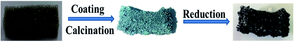 | ||
| Fig. 1 Optical photos of the pure sponge, the sponge saturated in precursor solution after calcination, and the black bulky sponge-shaped MoP (3D MoP). | ||
Fig. 2a shows the scanning electron microscopy (SEM) images of 3D MoP-650, where rich channels and well-defined macro-pores can be clearly observed. Fig. 2b shows a SEM image of nanoparticles with a size of several nanometers. These structural features can be further verified by a SEM image of the fracture plane of the pores’ side walls, as shown in Fig. S1.† Such a unique structure should be caused by gas release during the pyrolysis treatment, as indicated by the following equation:
| 2(NH4)6Mo7O24·4H2O + 14(NH4)2HPO4 → 14MoO3·7P2O5 + 40NH3↑ + 35H2O | (1) |
| 14MoO3·7P2O5 + 77H2 → 14MoP + 77H2O | (2) |
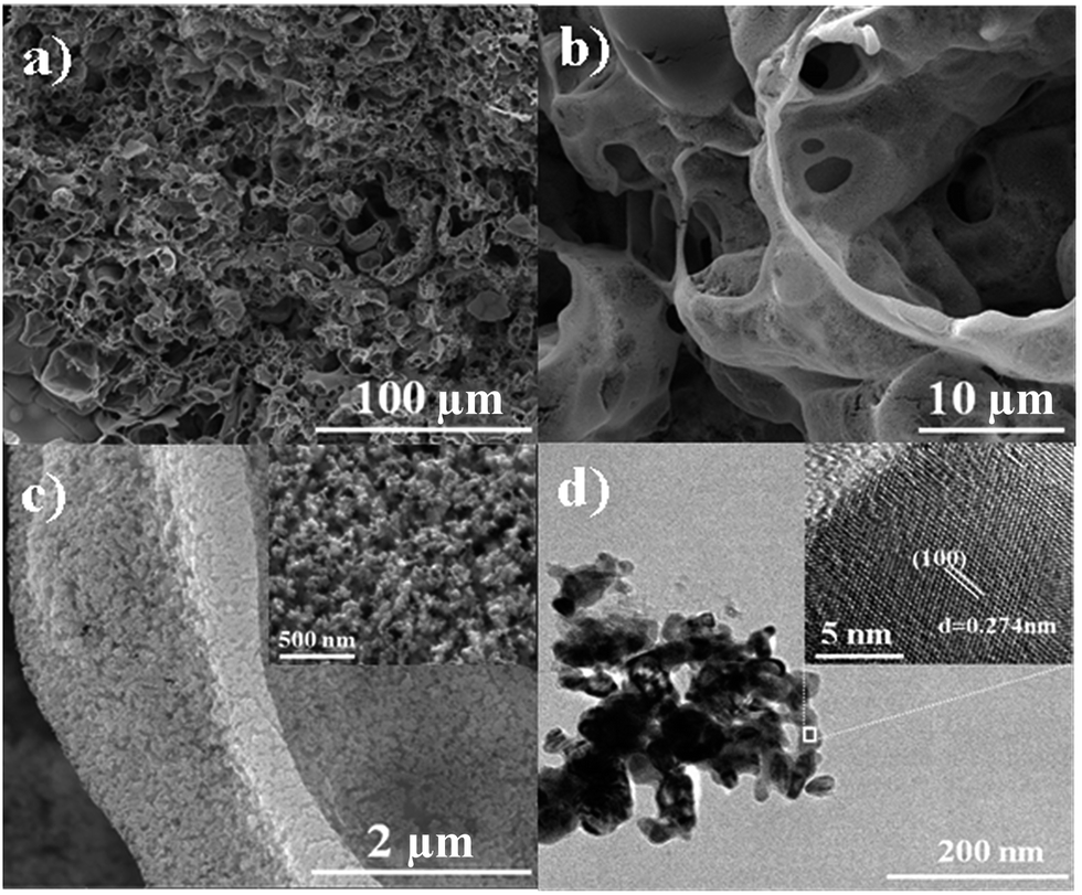 | ||
| Fig. 2 (a–c) SEM images of 3D MoP-650 at different magnification. (d) TEM image of 3D MoP-650, the inset shows the HRTEM image. | ||
The control experiment demonstrates that, without the loading of precursor solution, the sponge could be entirely removed after the pyrolysis treatment at 500 °C (Fig. S2†). Researchers have found that polyurethanes are thermosetting polymers where decomposition starts from 170 °C, intensifies from 200 °C and vaporizes at about 290 °C. When the temperature reaches 300 °C the polyurethane decomposition is practically completed.36 In addition, a bare MoP sample was prepared at 650 °C without using the sponge (PU) template. In order to confirm the existence of carbon on the surface of 3D MoP, Raman spectra of 3D MoP-650 and bare MoP-650 were conducted. Both samples showed the same Raman peaks and there was no carbon peaks observed in Fig. S3.†
Fig. S4† shows the SEM images of the bare MoP sample, revealing that it consists of disordered and aggregated particles. Clearly, neither a regular porous structure nor a refined side wall was observed. This can be further verified by the nitrogen adsorption/desorption isotherms, as shown in Fig. S5.† For 3D MoP-650 and bare MoP-650, the BET surface areas of 11.548 m2 g−1 and 9.851 m2 g−1, average pore sizes of 33.48 nm and 17.92 nm, and pore volumes of 0.085 cm3 g−1 and 0.052 cm3 g−1 were obtained, respectively. Table S1† gives the details of higher magnification BET for different 3D samples, revealing that 3D MoP-650 possesses an ideal loose structure which consists of plenty of mesopores and macropores which are beneficial for gas evolution, and the highest active surface area which can accelerate interfacial electrocatalytic reactions, resulting in effective charge transfer. With an increase of temperature, the aggregation of the particles increased, which can decrease the active surface area and pore size. Also, the thickness of the pore side walls of 3D MoP-650 can be estimated to be ca. 1 μm. Interestingly, a close inspection of the structure of the sample, as shown in Fig. 2c and the inset, reveals that the side walls of the pores are very refined. As can be seen, these huge differences strongly suggest that the sponge template plays a critical role in determining the unique structure of the 3D MoP-650 sample. The sponge not only acts as an initial framework, but can also mediate the growth of particles and suppress the aggregation of MoP particles. As such, we anticipate that such a sponge-shaped 3D MoP with enriched porosity should possess high active surface area and help to accelerate its interfacial electrocatalytic reactions by allowing rapid charge transfer kinetics.
Fig. 2d shows the transmission electron microscopy (TEM) image of the 3D MoP-650 sample, displaying the nanoparticle-composed microstructure. Moreover, the high-resolution TEM (HR-TEM) image, the inset of Fig. 2d, shows clear, well-defined lattice fringes with a plane distance of 0.274 nm, which can be assigned to the typical (100) plane of molybdenum phosphide. Meanwhile, EDS measurements were conducted to reveal the mapping of elemental Mo and P distribution at the sample surface (Fig. S6†). We observed that both Mo and P elements were uniformly distributed in the obtained 3D MoP sample, suggesting that the as-prepared sponge-shaped sample is a characteristic MoP material.
To further confirm the compositional properties, X-ray diffraction (XRD) patterns of the 3D MoP samples obtained at different reduction temperatures were obtained. As shown in Fig. 3, the sample obtained at 550 °C (3D MoP-550) reveals characteristic peaks, which can be assigned to monoclinic molybdenum dioxide (JCPDS 32-0671) and cubic molybdenum phosphate (JCPDS 39-0026), respectively. Different from 3D MoP-550, other samples obtained at 600 °C, 650 °C, 700 °C and 750 °C show characteristic peaks at 27.9°, 31.2°, 43.1°, 57.5°, 58.0°, 65.0°, 67.0°, 67.9°, 74.3°, which could be assigned to the (001), (100), (101), (110), (002), (111), (200), (102), and (201) planes of molybdenum phosphide (JCPDS 24-0771), respectively. Obviously, the XRD results demonstrate that a typical molybdenum phosphide phase can't be formed at a 550 °C reduction temperature under a H2 atmosphere. The crystalline degree of the 3D MoP sample increases along with the reduction temperature. We found that only when the reduction temperature is higher than 600 °C, the obtained 3D MoP sample undergoes crystallization. As can be seen, 3D MoP-650, 3D MoP-700 and 3D MoP-750 display a well crystalline WC-type hexagonal structure, while 3D MoP-600 shows poor crystallization. For comparison, Fig. S7† shows the XRD of the bare MoP sample, which is similar to that of 3D MoP 650.
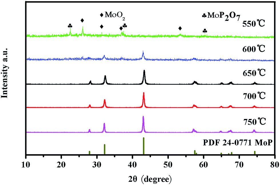 | ||
| Fig. 3 XRD patterns of 3D MoP samples obtained at different reduction temperatures. | ||
To verify the different valence states of individual elements in the 3D MoP samples, X-ray photoelectron spectroscopy (XPS) was adopted to characterize the binding energies of Mo and P. Fig. 4a shows that the species have one or more oxidation states at the surface of bulky 3D MoP. The samples obtained at reduction temperatures higher than 600 °C exhibit similar spectra with typically several doublets. Two doublets at ∼235.5 eV/232.3 eV (Mo6+ 3d3/2/3d5/2) and ∼231.9 eV/228.8 eV (Mo4+ 3d3/2/3d5/2) should be assigned to MoO3 and MoO2, respectively.3,37 These species might have been formed during the passivation treatment. According to previous studies, a Mo 3d doublet at ∼227.8 eV/231.0 eV indicative of Moδ+ species (0 < δ ≤ 4) generally can be assigned to the molybdenum element of molybdenum phosphide.31,33,38,39 Of note, 3D MoP-550 exhibits only two characteristic peaks at 232.3 and 235.5 eV, which can be assigned to Mo6+. The XPS results show that no Moδ+ species can be observed for 3D MoP-550, which is consistent with the XRD results. Also, for the profiles of P 2p, the 3D MoP-550 sample only exhibits a peak at a high binding energy of ∼133.8 eV, which could be ascribed to PO43− or P2O5.39 In contrast, other samples display two peaks at 130.1 and 129.3 eV, which should be assigned to the binding energy (BE) of P 2p1/2 and P 2p3/2 (in Fig. 4b), respectively.28,31 As can be seen, the BE of Moδ+ species is higher than metallic Mo0 (227.6 eV), thereby Moδ+ has a strong binding affinity to H. Apart from this, the major P species with a BE of 129.3 eV can be assigned to Pδ− bonded to Mo atoms. It is known that Pδ− can induce a charge transfer from molybdenum to phosphorus, which can consequently downshift the d-band center of molybdenum in 3D MoP and thereby decrease Mo–H binding energy. According to previous research,40 the strong molybdenum–hydrogen bonds on the surface may inhibit hydrogen release from the active sites, but a simple phosphorization of molybdenum to form MoP introduces a good ‘H delivery’ system which can potentially modify the properties of the molybdenum metal, presenting excellent catalytic activity in a combination of experimental results and theoretical calculations.3 Such an interaction benefits from the electrochemical desorption of Hads and leads to a relatively moderate Mo–H binding strength,31,38,41 therefore accelerating the hydrogen evolution reaction. Table S2† summaries the information derived from the XPS of 3D MoP samples prepared at different reduction temperatures. As can be seen, the ratio of P:Mo decreases and the content of Pδ− and Moδ+ increases with the increase of reduction temperature. It has been reported that Mo serves as the active center of the hydride-acceptor and P acts as the proton-acceptor center to facilitate the formation of Mo-hydride for subsequent hydrogen evolution via electrochemical desorption. Specifically, P sites can bond hydrogen at low coverage and desorb hydrogen at high coverage.31,42–45 Therefore, it is reasonable to conclude that there should be an optimized Moδ+:Pδ− for achieving the best HER performance.
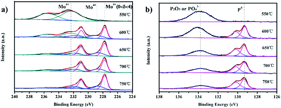 | ||
| Fig. 4 X-ray photoelectron spectra (XPS) of the as-prepared 3D MoP samples: (a) Mo 3d region and (b) P 2p region. | ||
To further examine the catalytic activity of the 3D MoP samples, their HER performance was investigated in 0.5 M H2SO4 with a scan rate of 2 mV s−1. In a typical three-electrode system, the 3D bulky MoP sample was used directly as a working electrode without further treatment. The current of the 3D MoP electrode was collected by using Ag wire as a collector. Linear scanning voltammetry plots were recorded after an activation process at a scan rate of 100 mV s−1 from +0.1 V to −0.3 V vs. the RHE. We observed that the catalytic current became stable after 10 cycles of activation. Fig. 5a shows the polarization curves for all of the prepared 3D MoP samples. We noted that there is no plateau at the beginning of the polarization curves, which is in agreement with previously reported results.21,46 As can be seen, 3D MoP-650 exhibits the highest HER efficiency among all the 3D MoP samples. The reduction current density increases rapidly along with negative potential scanning. The current density can approach 10 mA cm−2 and 20 mA cm−2 at an overpotential of 105 mV and 155 mV, respectively. Meanwhile, it is clear that the HER activity of the samples exhibits a decreasing tendency along with the increase of reduction temperature. In considering that the samples may have different weight, Fig. 5b presents the measured current of polarization curves normalized to the weight of the samples, from which the tendency of HER activity for the samples is consistent with that observed in Fig. 5a. The results apparently suggest that a proper reduction temperature for preparing the 3D MoP samples should determine the HER performance.
 | ||
| Fig. 5 Linear sweep voltammetry (LSV) curves of 3D MoP samples normalized to (a) the surface area and (b) the total weight in 0.5 M H2SO4 at a scan rate of 2 mV s−1. (c) The Tafel plots and the fitted slopes for the 3D MoP samples. (d) The Nyquist plots of the 3D MoP samples fitted to an equivalent circuit model. | ||
In general, the electrochemical evaluation of HER activity for various electrocatalysts is represented by the kinetic values of the constants a and b, which are calculated from the Tafel equation (η = blogj + a). The constant b, known as the Tafel slope which reflects the intrinsic property of catalysts, can be used to understand the reaction mechanism. The value of b is determined by the rate-limiting step of the HER. As reported,20 Tafel slopes of 30, 40, and 120 mV dec−1 correlate with different rate determining steps of the HER. Another important parameter for judging the inherent electrocatalytic activity of electrocatalysts is the exchange current density (j0), which represents a significant kinetic factor of the electrochemical reaction rate at the equilibrium state. It reflects how rapidly an electrochemical reaction can occur with an electrocatalyst.48 The value of j0 can deduced from the linear area of a Tafel plot, corresponding to the intercept at the overpotential η = 0. Fig. 5c displays the Tafel plots derived from the fitted polarization curves of the 3D MoP samples. The Tafel slopes are 162, 145, 126, 182, and 210 mV dec−1 for the 3D MoP samples of 750 °C, 700 °C, 650 °C, 600 °C, and 550 °C, respectively. We note that the Tafel slopes for all the 3D MoP samples are much larger than the values for other reported MoP3,30–32 (40–70 mA dec−1). This suggests that the HER mechanism for the 3D MoP samples might be quite different from the typical Heyrovsky reaction or Tafel reaction.46 In fact, the value of the Tafel slope can be influenced by several factors, including the reaction pathway and the adsorption conditions of the active site.27,47 Despite that more detailed work is needed to illustrate this, we propose that the unique 3D structure full of channels and porosity might affect the observed Tafel slope of the MoP samples. Molybdenum phosphide is a good conductor of electricity compared with other semi-conductors and displays metallic character, as shown by density functional theory (DFT) analyses. However, as an oxide layer is produced on the surface during preparation and storage, the conductivity of 3D MoP would be affected overall which would decrease its conductivity. Without other conductive materials or additional electrode materials to support, the 3D MoP samples presented massively higher Tafel slopes than the Tafel slope of the MoP modified GCE electrode due to their large oxide surface and unique structure. Among all the samples, 3D MoP-650 exhibits the smallest Tafel slope of 126 mV dec−1 and the largest exchange current density of 3.052 mA cm−2. To understand this, the electrochemical impedance spectroscopy (EIS) technique was applied to examine the 3D MoP samples under acidic conditions. The Nyquist plots of the samples and the corresponding electrical equivalent circuit diagram are given in Fig. 5d. As shown, 3D MoP-650 exhibits a much lower charge-transfer impedance (Rct) of ∼0.5 Ω compared to the other samples. Table 1 lists the obtained electrochemical parameters, in terms of Tafel slope, impedance and exchange current density, for all 3D MoP samples. The observed promising performance for 3D MoP-650 should be ascribed to the following reasons: (1) the significantly small impedance affords markedly faster HER kinetics. (2) The high surface area and porous structure offer more exposed active sites and enable the rapid diffusion of species during the reactions. (3) A good crystalline structure and appropriate Moδ+:Pδ− ratio might contribute to the high activity.
| 550 °C | 600 °C | 650 °C | 700 °C | 750 °C | |
|---|---|---|---|---|---|
| Tafel slope b (mV dec−1) | 210 | 182 | 126 | 145 | 162 |
| Exchange current density (mA cm−2) | 0.106 | 0.599 | 3.052 | 1.172 | 0.833 |
| Charge-transfer impedance (Ω) | 10.5 | 1.4 | 0.5 | 1.9 | 3.0 |
Next, it is necessary to verify the advantages of the bulky 3D structure of MoP in the HER. For this purpose, 3D MoP-650 was ground into a powder (called P-MoP) and modified on a glassy carbon electrode (GCE). For comparison, a bare GCE, commercial Pt/C (5 wt% Pt/XC-72) and bare MoP reduced at 650 °C were also studied. As shown in Fig. S8a,† the bare GCE shows almost no HER activity, while bare MoP exhibits higher activity than the bare GCE. In contrast, the P-MoP modified GCE has relatively high activity toward the HER with an onset overpotential of 60 mV (vs. RHE). Also, it can approach a current density of 2 and 10 mA cm−2 at an overpotential of 115 mV and 191 mV, respectively. Fig. S8b† shows the Tafel plots derived from the polarization measurements. As can be seen, P-MoP shows a Tafel slope of 56 mV dec−1, which is similar to the values reported by other groups.3,31 The TOF per active site for the P-MoP is calculated to be 0.90 s−1 (vs. 0.14 s−1 for bare MoP) at η = 0 mV s−1. Therefore, our templated synthetic method provides a facile and green route to prepare a high-performance HER catalyst. Obviously, P-MoP has better HER performance than bare MoP, which can be probably explained by the fact that P-MoP possesses a refined nanoparticle assembled structure and should expose more active sites. Specifically, we found that the 3D bulky MoP electrode possesses much higher HER activity than the P-MoP modified electrode. It indicates that the 3D and bulky structure has superior performance in the HER. Two reasons might be responsible for the observed results. On one hand, the P-MoP modified electrode was prepared by using polymer binder to immobilize the electrocatalyst, which correspondingly increases the resistance,49 blocks some active sites and inhibits gas diffusion, thereby deteriorating the overall catalytic activity of the electrode.50 On the other hand, the 3D MoP sponge electrode offers large surface area, rich interconnected channels, and ideal porosity, which are extremely beneficial for catalytic reactions and gas evolution. We also compare the performance of the 3D MoP sample with other Mo-based HER electrocatalysts. As shown in Table S3,† the as-prepared 3D MoP outperforms most of the reported HER electrocatalysts.
Apart from the electrochemical activity, stability is another vital factor for judging an electrocatalyst. To this end, the long-term stability of the 3D MoP electrode was investigated in 0.5 M H2SO4 by maintaining an overpotential of 110 mV. Fig. 6 shows that the reduction current density remained at around 11 mA cm−2 even after 60000 s of continuous operation, where almost 96% of the initial current was kept. For a sharp comparison, only 78% and 82% of initial current density was maintained for the P-MoP electrode and Pt/C, respectively (Fig. S9†). These results demonstrate that the 3D bulky electrode has superior stability in a long-term electrochemical process over a traditional catalyst powder modified electrode. To verify the composition of the sample, we further characterized the 3D MoP-650 sample with XRD and XPS after the long-term stability test. As illustrated in Fig. S10,† the XRD peaks of the sample before and after the long term test remained the same, indicating the same crystallographic structure. In Fig. S11,† we found that the constituent of the 3D MoP-650 sample remained stable and there is not much distinction after testing except that the relative intensities of its Mo 3d5/2 and P 2p3/2 peaks with higher binding energies were lower than before which could be attributed to active hydrogen species H possessing high reduction ability, reducing molybdenum and phosphorus oxides during testing. However, the intensity of molybdenum and phosphorus oxides increased after long-term storage again, which could be attributed to the long-term exposure to air during practical operation. We have supplemented the SEM of the sample after the long-term electrochemical test as shown in Fig. S12.† After electrochemical testing for 60000 s, the 3D porous structure of the sample didn't change (Fig. S12a†). However, the surface of the sample became rougher, which can be attributed to the generation of the bubbles during the HER process. During the experiments for P-MoP and Pt/C, we observed that the freshly formed hydrogen bubbles were strongly absorbed on the electrode surface and hardly detached until they grew larger. Such a feature is undesirable as the adhesion of bubbles not only lowers the gas evolution rate, but also increases the risk of catalyst corrosion. It has been proved that porous structures and rough surfaces contribute to the suppression of gas bubble adhesion, and enhance electrode stability by accelerating the detaching process of the hydrogen bubbles.51 To clarify this, Fig. S13† shows pictures of the 3D MoP-650 electrode in the solution before and during the HER. As can be seen, the small sized H2 bubbles were found to evolve from the bulky electrode. Moreover, Movie S1† clearly displays the working process for hydrogen production on 3D MoP-650 operated from +0.05 V to −0.35 V. As a result, it strongly demonstrates that the 3D MoP sponge electrode is highly efficient and favorable for hydrogen production using electrochemical water-splitting. Although Pt-based catalysts have been widely studied for the HER, very few catalysts show high performance under both acidic and basic conditions. Recently, some solid-state catalysts have emerged as efficient HER catalysts which can operate in both acidic and basic solutions.3,15,52 In this work, we also investigated the activity of 3D MoP under basic conditions. As shown in Fig. S14a,† the activity of 3D MoP-650 in 1 M KOH is surprisingly as high as that in acidic solutions. Remarkably, the durability of the 3D MoP electrode in 1 M KOH was also tested (Fig. S14b†). Nearly 93% of the initial current was maintained, indicating that the 3D MoP electrode has superior tolerance to solution pH. Nevertheless, we noted that further studies are necessary to understand the mechanism of 3D MoP in strong acid and alkaline solution.
 | ||
| Fig. 6 Time dependence of catalytic current density during electrolysis for 3D MoP-650 in 0.5 M H2SO4 at an overpotential of 90 mV. | ||
Finally, we used gas chromatography (GC) to detect the gaseous product from the 3D-MoP electrode. As shown in Fig. 7, only H2 was detected without any other product, implying that the electrode works well for hydrogen evolution. Furthermore, the amount of collected H2 shows a linear dependence along with increasing time of electrolysis. By taking into account the charge passed through the cell, the faradaic efficiency for the HER using the 3D-MoP electrode was calculated to be nearly 100%. This strongly suggests that the bulky 3D MoP sponge can serve as a high performance electrode for electrochemical hydrogen production. Importantly, the unique structural features afford 3D MoP sponge with high applicability, by tailoring the size and coupling with electrochemical devices in practical applications.
 | ||
| Fig. 7 GC chromatograph of H2 gas production obtained with 3D MoP-650 under electrolysis at −0.2 V (vs. RHE) for 1 h. The inset shows the volume of hydrogen and the testing time. | ||
4. Conclusions
In summary, we have reported a simple synthetic strategy for the preparation of a bulky 3D MoP electrode for the HER by using low-cost commercial sponge as a sacrificial template. The prepared MoP materials showed a unique sponge-shaped structure consisting of rich channels and pores, which are beneficial for gas evolution. Significantly, the side walls of the pores were composed of well-defined nanoparticles, endowing the materials with high surface area and many exposed active sites. 3D MoP-650 afforded a relatively small Tafel slope of 126 mV dec−1, a high exchange current density of 3.052 mA cm−2, and a faradaic efficiency of nearly 100% in acidic electrolyte. Only 105 mV of overpotential was needed to achieve a 10 mA cm−2 current density. In addition, this novel bulky HER electrode showed high tolerance and promising durability both under acidic and basic conditions. Importantly, the unique structural features and compositional properties endow 3D MoP sponge with the advantage of easy coupling with different electrochemical devices by tailoring the electrode size without adding any binder agent or conductive support. Therefore, this work essentially offers a cheap, viable and scalable strategy for preparing highly efficient HER electrocatalysts for use in electrochemical water-splitting technology.Acknowledgements
Financial support from the Ministry of Science and Technology (2012DFR40240), National Natural Science Foundation of China (Grant no. 21175012), and the Chinese Ministry of Education (Project of New Century Excellent Talents in University: NCET-10-0048) is gratefully acknowledged.Notes and references
- J. A. Turner, Science, 2004, 305, 972–974 CrossRef CAS PubMed.
- N. S. Lewis, Science, 2007, 315, 798–801 CrossRef CAS PubMed.
- P. Xiao, M. A. Sk, L. Thia, X. Ge, R. J. Lim, J. Y. Wang, K. H. Lima and X. Wang, Energy Environ. Sci., 2014, 7, 2624–2629 CAS.
- M. G. Walter, E. L. Warren, J. R. McKone, S. W. Boettcher, Q. Mi, E. A. Santori and N. S. Lewis, Chem. Rev., 2010, 110, 6446–6473 CrossRef CAS PubMed.
- Y. Hara, N. Minami, H. Matsumoto and H. Itagaki, Appl. Catal., A, 2007, 332, 289–296 CrossRef CAS.
- H. B. Gray, Nat. Chem., 2009, 1, 7–7 CrossRef CAS PubMed.
- D. V. Esposito, S. T. Hunt, A. L. Stottlemyer, K. D. Dobson, B. E. McCandless, R. W. Birkmire and J. G. Chen, Angew. Chem., Int. Ed., 2010, 49, 9859–9862 CrossRef CAS PubMed.
- T. F. Jaramillo, K. P. Jorgensen, J. Bonde, J. H. Nielsen, S. Horch and I. Chorkendorff, Science, 2007, 317, 100–102 CrossRef CAS PubMed.
- Y. Hou, B. Zhang, Z. H. Wen, S. M. Cui, X. R. Guo, Z. He and J. H. Chen, J. Mater. Chem. A, 2014, 2, 13795–13800 CAS.
- J. Kibsgaard, Z. Chen, B. N. Reinecke and T. F. Jaramillo, Nat. Mater., 2012, 11, 963–969 CrossRef CAS PubMed.
- Z. Chen, D. Cummins, B. N. Reinecke, E. Clark, M. K. Sunkara and T. F. Jaramillo, Nano Lett., 2011, 11, 4168–4175 CrossRef CAS PubMed.
- J. Deng, H. Li, J. Xiao, Y. Tu, D. Deng, H. Yang, H. Tian, J. Li, P. Ren and X. Bao, Energy Environ. Sci., 2015, 8, 1594–1601 CAS.
- W. Chen, C. Wang, K. Sasaki, N. Marinkovic, W. Xu, J. T. Muckerman, Y. Zhu and R. R. Adzic, Energy Environ. Sci., 2013, 6, 943–951 CAS.
- L. Liao, S. Wang, J. Xiao, X. Bian, Y. Zhang, M. D. Scanlon, X. Hu, Y. Tang, B. Liu and H. H. Girault, Energy Environ. Sci., 2014, 7, 387–392 CAS.
- H. Vrubel and X. Hu, Angew. Chem., Int. Ed., 2012, 51, 12703–12706 CrossRef CAS PubMed.
- D. Kong, H. Wang, J. J. Cha, M. Past, K. J. Koski, J. Yao and Y. Cui, Nano Lett., 2013, 13, 1341–1347 CrossRef CAS PubMed.
- W. F. Chen, K. Sasaki, C. Ma, A. I. Frenkel, N. Marinkovic, J. T. Muckerman, Y. Zhu and R. R. Adzic, Angew. Chem., Int. Ed., 2012, 51, 6131–6135 CrossRef CAS PubMed.
- J. Yang and H. S. Shin, J. Mater. Chem. A, 2014, 2, 5979–5985 CAS.
- J. Bonde, P. G. Moses, T. F. Jaramillo, J. K. Nørskov and I. Chorkendorff, Faraday Discuss., 2008, 140, 219–231 RSC.
- Y. Li, H. Wang, L. Xie, Y. Liang, G. Hong and H. Dai, J. Am. Chem. Soc., 2011, 133, 7296–7299 CrossRef CAS PubMed.
- Y. H. Chang, C. T. Lin, T. Y. Chen, C. L. Hsu, Y. H. Lee, W. Zhang, K. H. Wei and L. J. Li, Adv. Mater., 2013, 25, 756–760 CrossRef CAS PubMed.
- P. Liu and J. A. Rodriguez, J. Am. Chem. Soc., 2005, 127, 14871–14878 CrossRef CAS PubMed.
- Y. Bai, H. Zhang, X. Li, L. Liu, H. Xu, H. Qiu and Y. Wang, Nanoscale, 2015, 7, 1446–1453 RSC.
- J. Tian, Q. Liu, A. M. Asiri and X. Sun, J. Am. Chem. Soc., 2014, 136, 7587–7590 CrossRef CAS PubMed.
- Z. Pu, Q. Liu, P. Jiang, A. M. Asiri, A. Y. Obaid and X. Sun, Chem. Mater., 2014, 26, 4326–4329 CrossRef CAS.
- E. J. Popczun, C. G. Read, C. W. Roske, N. S. Lewis and R. E. Schaak, Angew. Chem., Int. Ed., 2014, 53, 5427–5430 CrossRef CAS PubMed.
- Y. Xu, R. Wu, J. Zhang, Y. Shi and B. Zhang, Chem. Commun., 2013, 49, 6656–6658 RSC.
- P. Jiang, Q. Liu, Y. Liang, J. Tian, A. M. Asiri and X. Sun, Angew. Chem., Int. Ed., 2014, 53, 12855–12859 CrossRef CAS PubMed.
- S. T. Oyama, J. Catal., 2003, 216, 343–352 CrossRef CAS.
- X. Chen, D. Wang, Z. Wang, P. Zhou, Z. Wu and F. Jiang, Chem. Commun., 2014, 50, 11683–11685 RSC.
- Z. Xing, Q. Liu, A. M. Asiri and X. Sun, Adv. Mater., 2014, 26, 5702–5707 CrossRef CAS PubMed.
- J. M. McEnaney, J. C. Crompton, J. F. Callejas, E. J. Popczun, A. J. Biacchi, N. S. Lewis and R. E. Schaak, Chem. Mater., 2014, 26, 4826–4831 CrossRef CAS.
- J. Kibsgaard and T. F. Jaramillo, Angew. Chem., 2014, 126, 1–6 CrossRef.
- Z. Y. Yang, L. J. Jin, G. Q. Lu, Q. Q. Xiao, Y. X. Zhang, L. Jing, X. X. Zhang, Y. M. Yan and K. N. Sun, Adv. Funct. Mater., 2014, 24, 3917–3925 CrossRef CAS.
- Y. F. Xu, M. R. Gao, Y. R. Zheng, J. Jiang and S. H. Yu, Angew. Chem., Int. Ed., 2013, 52, 8546–8550 CrossRef CAS PubMed.
- R. Bilbao, J. F. Mastral, J. Ceamanos and M. E. Aldea, J. Anal. Appl. Pyrolysis, 1996, 37, 69–82 CrossRef CAS.
- X. Zhao, M. Cao, B. Liu, Y. Tian and C. Hu, J. Mater. Chem., 2012, 22, 13334–13340 RSC.
- D. C. Phillips, S. J. Sawhill, R. Self and M. E. Bussell, J. Catal., 2002, 207, 266–273 CrossRef CAS.
- J. Bai, X. Li, A. Wang, R. Prins and Y. Wang, J. Catal., 2012, 287, 161–169 CrossRef CAS.
- Q. Yue, Y. Wan, Z. Sun, X. Wu, Y. Yuan and P. Du, J. Mater. Chem. A, 2015, 3, 16941–16947 CAS.
- R. Wang and K. J. Smith, Appl. Catal., A, 2009, 363, 18–25 CrossRef.
- A. B. Laursen, S. Kegnaes, S. Dahl and I. Chorkendorff, Energy Environ. Sci., 2012, 5, 5577–5591 CAS.
- W. Zhang, J. Hong, J. Zheng, Z. Huang, J. Zhou and R. Xu, J. Am. Chem. Soc., 2011, 133, 20680–20683 CrossRef CAS PubMed.
- A. D. Wilson, R. H. Newell, M. J. McNevin, J. T. Muckerman, M. R. Dubois and D. L. Dubois, J. Am. Chem. Soc., 2006, 128, 358–366 CrossRef CAS PubMed.
- B. E. Barton and T. B. Rauchfuss, J. Am. Chem. Soc., 2010, 132, 14877–14885 CrossRef CAS PubMed.
- Y. H. Chang, F. Y. Wu, T. Y. Chen, C. L. Hsu, C. H. Chen, F. Wiryo, K. H. Wei, C. Y. Chiang and L. J. Li, Small, 2014, 10, 895–900 CrossRef CAS PubMed.
- B. E. Conway and B. V. Tilak, Electrochim. Acta, 2002, 47, 3571–3594 CrossRef CAS.
- Y. Yan, B. Xia, Z. Xu and X. Wang, ACS Catal., 2014, 4, 1693–1705 CrossRef CAS.
- Y. Luo, J. Jiang, W. Zhou, H. Yang, J. Luo, X. Qi, H. Zhang, D. Y. W. Yu, C. M. Li and T. Yu, J. Mater. Chem., 2012, 22, 8634–8640 RSC.
- J. D. Roy-Mayhew, G. Boschloo, A. Hagfeldt and I. A. Aksay, ACS Appl. Mater. Interfaces, 2012, 4, 2794–2800 CAS.
- Z. Lu, W. Zhu, X. Yu, H. Zhang, Y. Li, X. Sun, X. Wang, H. Wang, J. Wang, J. Luo, X. Lei and L. Jiang, Adv. Mater., 2014, 26, 2683–2687 CrossRef CAS PubMed.
- X. Zou, X. Huang, A. Goswami, R. Silva, B. R. Sathe, E. Mikmeková and T. Asefa, Angew. Chem., Int. Ed., 2014, 53, 4372–4376 CrossRef CAS PubMed.
Footnote |
| † Electronic supplementary information (ESI) available: Fig. S1–S14, Tables S1–S3, and Movie S1. See DOI: 10.1039/c5ta05453b |
| This journal is © The Royal Society of Chemistry 2016 |