 Open Access Article
Creative Commons Attribution 3.0 Unported Licence
Taylor line swimming in microchannels and cubic lattices of obstacles†
Jan L.
Münch
a,
Davod
Alizadehrad
ab,
Sujin B.
Babu
c and
Holger
Stark
*a
aInstitut für Theoretische Physik, Technische Universität Berlin, Hardenbergstr. 36, D-10623 Berlin, Germany. E-mail: Holger.Stark@tu-berlin.de; Web: http://www.itp.tu-berlin.de/stark
bForschungszentrum Jülich, Wilhelm-Johnen-Straße, D-52425 Jülich, Germany
cDepartment of Physics, Indian Institute of Technology Delhi, Hauz Khas, New Delhi-110016, India
First published on 15th July 2016
Abstract
Microorganisms naturally move in microstructured fluids. Using the simulation method of multi-particle collision dynamics, we study in two dimensions an undulatory Taylor line swimming in a microchannel and in a cubic lattice of obstacles, which represent simple forms of a microstructured environment. In the microchannel the Taylor line swims at an acute angle along a channel wall with a clearly enhanced swimming speed due to hydrodynamic interactions with the bounding wall. While in a dilute obstacle lattice swimming speed is also enhanced, a dense obstacle lattice gives rise to geometric swimming. This new type of swimming is characterized by a drastically increased swimming speed. Since the Taylor line has to fit into the free space of the obstacle lattice, the swimming speed is close to the phase velocity of the bending wave traveling along the Taylor line. While adjusting its swimming motion within the lattice, the Taylor line chooses a specific swimming direction, which we classify by a lattice vector. When plotting the swimming velocity versus the magnitude of the lattice vector, all our data collapse on a single master curve. Finally, we also report more complex trajectories within the obstacle lattice.
I. Introduction
The motility of microorganisms in their liquid environment is important in various biological processes.1 Microorganisms move in the low-Reynolds-number regime, where viscous forces dominate over inertia.2 They have developed various swimming strategies to cope with the strong viscous forces2 including beating flagellar appendages of sperm cells,3,4 metachronal waves of collectively moving cilia on the cell surface of a paramecium,5 rotating helical flagella in E. coli,6–10 and periodic deformations of the whole cell body.11–13 The first expression for the swimming speed of a simplified flagellar model was given by Taylor in 1951.14,15 In this model a prescribed bending wave moves along a filament, which we call the Taylor line in the following. A recent study on the Taylor line showed hydrodynamic phase locking of multiple flagella16 and ref. 17 determined the optimal shape of a large amplitude wave. These insights into biological swimming mechanisms in Newtonian liquids inspired the studies of artificial swimmers in unbound18,19 as well as bound20,21 fluids.Following the seminal experiments of Rothschild in 1963,22 artificial microchannels have extensively been used to investigate the influence of bounding walls on locomotion.13,23–36 Hydrodynamic interactions of sperm cells with channel walls37–42 and with other cells43 are of special interest in reproductive medicine.
In vivo the motility of protozoa and small eukaryotic organisms is influenced by obstacles in the liquid environment such as cells44–46 and proteins,47–51 but also studies with artificially produced posts exist.11,52,53 Not only the shape of the obstacles is important but they also can make the liquid environment viscoelastic. Examples in nature of biological or medical relevance include microorganisms in soil,52,53 in blood,44–46 or in mucus.54–57 The mucus of the cervix uteri, for example, consists of a dense polymer network. This polymer network induces a hydrodynamic sorting process. Sperm with normal swimming motion are able to pass the network whereas for defective sperm cells the mucus is hardly penetrable.4 Model swimmers with large-amplitude deformations of their driving filament show speed enhancement in viscoelastic fluids,58,59 while for small-amplitude deformations viscoelasticity hinders faster swimming.50,58,60–62 Experiments with C. elegans in viscoelastic fluids confirm the prediction of slower swimming.49,63
In 1979 L. Turner and H. C. Berg suggested that the geometric constraints of polymer networks in viscoelastic fluids can drastically enhance the swimming speed of microorganisms.48 Based on experimental observations with helical bacteria they formulated the following picture. When rotating about their helical axis, bacteria with helical shape move through a polymeric liquid like through a quasi-rigid medium and similar to a corkscrew driven into cork. So, in the ideal case, after each full rotation the bacterium would proceed by one full pitch length. In this paper we will investigate another type of this geometrical swimming by studying the Taylor line in a cubic lattice of obstacles.
A typical example of obstacles in nature is erythrocytes or red blood cells. The African trypanosome, the causative agent of sleeping sickness, swims faster in the crowded environment of blood and thereby removes surface-bound antibodies with the help of hydrodynamic drag forces.46 In this way, the parasite evades the immune response of its host. The motility of the African trypanosome in a Newtonian liquid was investigated in bulk fluid by computer modeling64–66 and in Poiseuille flow.34 Blood is a complex viscoelastic liquid containing a large amount of cellular components, which gives blood a non-Newtonian character. Its viscosity depends on the volume fraction of erythrocytes (hematocrit), shear rate, and temperature.67,68 In order to understand the geometrical constraints of erythrocytes for the motility of the trypanosome or how other obstacles influence the swimming of sporozoites or C. elegans, more controlled experiments were conducted. They use either suspended colloids63,69 or fabricated lattices of posts.11,52,53,70,71
In lab-on-chip devices obstacle lattices are used to separate trypanosomes from erythrocytes with the idea to diagnose the sleeping sickness in an early stage.72 Trypanosomes swimming in these lattices show a motility much more comparable to their in vivo motility due to interactions with the obstacles.11 Similarly, Park et al. found that C. elegans, a worm-like microorganism, swims up to ten times faster in an obstacle lattice compared to its swimming speed in bulk fluid.52 The speed-up depended on the lattice spacing. A combined experimental and numerical study by Majmudar et al. on an undulatory swimmer such as C. elegans showed that most of the characteristics of this new type of swimming in an array of micro-pillars can be explained by a mechanical model for the swimmer.53 It does not need any biological sensing or behavior.
In this paper we present a detailed hydrodynamic study of an undulatory Taylor line (a one-dimensional object) swimming in a two-dimensional microchannel and in a two-dimensional cubic lattice of obstacles. We use the method of multi-particle collision dynamics for simulating the hydrodynamic flow fields.73 In the microchannel the Taylor line swims at an acute angle along a channel wall with a clearly enhanced swimming speed. In a dilute obstacle lattice swimming speed is also enhanced due to hydrodynamic interactions with the obstacles similar to a study by Leshansky.74 Moving the obstacles closer together (dense obstacle lattice), the undulatory Taylor line has to fit into the free space of the obstacle lattice, where it performs geometric swimming. Here, the swimming speed is close to the wave velocity of the bending wave traveling along the Taylor line. In this regime, we classify the possible swimming directions by lattice vectors. When plotting the ratio of swimming and wave velocity versus the magnitude of the lattice vector (effective lattice constant), all our data collapse on a single master curve. This demonstrates the regime of geometric swimming. We also illustrate more complex trajectories. With our study, we contribute to the understanding of undulatory biological microswimmers, such as the African trypanosome or C. elegans in complex environments.
The article is structured as follows. In Section II we introduce our computational methods including the method of multi-particle collision dynamics and the implementation of the Taylor line. In Section III we calibrate the parameters of the Taylor-line model by studying its swimming motion in the bulk fluid. In Sections IV and V we review the respective results for swimming in the microchannel and in the obstacle lattice. Section VI closes with a summary and conclusions.
II. Computational methods
A. Multi-particle collision dynamics
We employ the method of multi-particle collision dynamics (MPCD) to simulate the Taylor line in its two-dimensional fluid environment.75–77 This method has been applied to various physical problems reviewed in ref. 73 and 78. Of particular interest to the present work on MPCD one can implement no-slip boundary conditions and therefore reproduce flow fields in channels,79,80 around circular79,81 or cubic cylinders,81 and around passive spheres82 in good agreement with analytical formulae. Furthermore, microswimmers moving by surface deformations can be simulated by coupling them to the surrounding fluid at low Reynolds numbers.38,64–66 Recent theoretical studies in two dimensions simulate a moving fish,83 the sedimentation of erythrocytes,84 and a binary colloidal suspension demixing under Poiseuille flow.85MPCD uses point particles of mass m0 as coarse-grained fluid particles. Their dynamics consists of a ballistic streaming and a collision step, which locally conserves momentum. Therefore, the resulting flow field satisfies the Navier–Stokes equations but also inherently includes thermal fluctuations.73
In the streaming step the positions ![[r with combining right harpoon above (vector)]](https://www.rsc.org/images/entities/i_char_0072_20d1.gif) i of all fluid particles are updated according to
i of all fluid particles are updated according to
![[r with combining right harpoon above (vector)]](https://www.rsc.org/images/entities/i_char_0072_20d1.gif) i(t + Δtc) = i(t + Δtc) = ![[r with combining right harpoon above (vector)]](https://www.rsc.org/images/entities/i_char_0072_20d1.gif) i(t) + i(t) + ![[v with combining right harpoon above (vector)]](https://www.rsc.org/images/entities/i_char_0076_20d1.gif) i(t)Δtc, i(t)Δtc, | (1) |
![[v with combining right harpoon above (vector)]](https://www.rsc.org/images/entities/i_char_0076_20d1.gif) i is the particle velocity and Δtc the MPCD time step between collisions.80
i is the particle velocity and Δtc the MPCD time step between collisions.80
After each streaming step the fluid particles are sorted into quadratic collision cells of linear dimension a0, so that on average each cell contains N = 10 particles with total mass M = Nm0 = 10. In each cell we redistribute the particles' velocities following a collision rule, for which we choose the Anderson thermostat with additional angular momentum conservation.80 At first we calculate the total momentum,  , of each collision cell. Then, we assign to each velocity component of a particle relative to the mean velocity
 ![[P with combining right harpoon above (vector)]](https://www.rsc.org/images/entities/i_char_0050_20d1.gif) cell/M a random component vi,rand from a Gaussian distribution with variance kBT/m0. Here, T is the temperature and kB the Boltzmann constant. Using the mean random momentum
cell/M a random component vi,rand from a Gaussian distribution with variance kBT/m0. Here, T is the temperature and kB the Boltzmann constant. Using the mean random momentum  of each cell, we determine the new particle velocities after the collision:
 | (2) |
![[small omega, Greek, vector]](https://www.rsc.org/images/entities/i_char_e13e.gif) ×
× ![[r with combining right harpoon above (vector)]](https://www.rsc.org/images/entities/i_char_0072_20d1.gif) i, to replace the new velocities
i, to replace the new velocities ![[v with combining right harpoon above (vector)]](https://www.rsc.org/images/entities/i_char_0076_20d1.gif) Ci,new by
Ci,new by![[v with combining right harpoon above (vector)]](https://www.rsc.org/images/entities/i_char_0076_20d1.gif) i,new = i,new = ![[v with combining right harpoon above (vector)]](https://www.rsc.org/images/entities/i_char_0076_20d1.gif) Ci,new − Δ Ci,new − Δ![[small omega, Greek, vector]](https://www.rsc.org/images/entities/i_char_e13e.gif) × × ![[r with combining right harpoon above (vector)]](https://www.rsc.org/images/entities/i_char_0072_20d1.gif) i. i. | (3) |
 | (4) |
 is the moment of inertia of the particles in the cell. This rule restores angular momentum conservation keeping linear momentum constant. By definition, the collision rule based on the Anderson thermostat also keeps the temperature constant. To restore Galilean invariance and the molecular chaos assumption, we always apply a random grid shift when defining the collision cells and take the shift from the interval [0,a0].86,87
In the following, we will measure quantities in typical MPCD units. We will use the linear dimension of the collision cell a0 as a unit for length, energies are measured in units of kBT = 1, and mass in units of m0. Then the time unit becomes  .82 In this unit, our time step between collisions is always chosen as Δtc = 0.01.
Transport coefficients of the MPCD fluid in two and three dimensions can be found in ref. 77. In particular, in MPCD units we obtain a shear viscosity of η ≈ 36 for the parameters in our simulations, in agreement with ref. 88. To calculate the Reynolds number Re = ρv2A/η, we use ρ = 10 (as introduced before), A is the amplitude of the undulation of the Taylor line, and v = 4Aω/2π estimates the velocity of the constituent beads, when moving up and down. The highest value in our simulations amounts to v = 0.06 in MPCD units, so that we work at Reynolds numbers below Re = 0.11. These are typical values used in two- and three-dimensional MPCD simulations for the low-Reynolds-number regime.43,88
All particle-based solvers of the Navier–Stokes equations describe, in principle, compressible fluids, which are characterized by the Mach number Ma = v/vsound. Here  is the sound velocity of the MPCD fluid in MPCD units and f is the spatial dimension. Since the compressibility scales with Ma2, the accepted regime in MPCD simulations for neglecting compressibility is Ma < 0.1.81–83 Using
  and the maximal value v = 0.06 from above, we arrive at the maximal value Ma ≈ 0.05, well in the regime where incompressibility can safely be assumed.
B. No-slip boundary condition: bounce-back rule and virtual particles
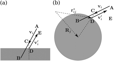
At bounding walls fluid flow obeys the no-slip boundary condition. To implement it within the MPCD method, we let the effective fluid particles interact with channel walls or obstacles using the bounce-back rule,81 see Fig. 1. When a fluid particle moves into an obstacle or a channel wall during the streaming step (position B), we invert the velocity![[v with combining right harpoon above (vector)]](https://www.rsc.org/images/entities/i_char_0076_20d1.gif) i′ = −
i′ = −![[v with combining right harpoon above (vector)]](https://www.rsc.org/images/entities/i_char_0076_20d1.gif) i and let the particle stream to position C during half the collision time:
i and let the particle stream to position C during half the collision time:![[r with combining right harpoon above (vector)]](https://www.rsc.org/images/entities/i_char_0072_20d1.gif) i(t + Δtc/2) = i(t + Δtc/2) = ![[r with combining right harpoon above (vector)]](https://www.rsc.org/images/entities/i_char_0072_20d1.gif) i(t) + i(t) + ![[v with combining right harpoon above (vector)]](https://www.rsc.org/images/entities/i_char_0076_20d1.gif) i′(t)Δtc/2. i′(t)Δtc/2. | (5) |
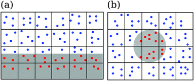
In addition, the no-slip boundary condition is improved using virtual particles inside a channel wall or an obstacle, see Fig. 2. We uniformly distribute virtual particles (red dots in Fig. 2) in the areas of the collision cells, which extend into the channel wall or obstacles. The velocity components are chosen from a Gaussian distribution with variance kBT/m0. The virtual particles also take part in the collision step. So, close to bounding walls one has the same average number of particles in a collision cell as in the bulk. Both rules together implement the no-slip boundary condition at a bounding surface in good approximation.80,81
C. A discrete model of the Taylor line
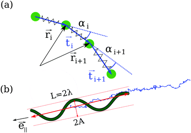
The Taylor line propels itself by running a sinusoidal bending wave along its contour line. Fig. 3(a) shows how we discretize the Taylor line by a bead-spring chain with N beads each of mass m = 10m0. The beads at positions![[r with combining right harpoon above (vector)]](https://www.rsc.org/images/entities/i_char_0072_20d1.gif) i interact with each other by a spring and a bending potential. The spring potential implements Hooke's law between nearest neighbors,19
i interact with each other by a spring and a bending potential. The spring potential implements Hooke's law between nearest neighbors,19 | (6) |
![[t with combining right harpoon above (vector)]](https://www.rsc.org/images/entities/i_char_0074_20d1.gif) i| = |
i| = |![[r with combining right harpoon above (vector)]](https://www.rsc.org/images/entities/i_char_0072_20d1.gif) i+1 −
i+1 − ![[r with combining right harpoon above (vector)]](https://www.rsc.org/images/entities/i_char_0072_20d1.gif) i| the actual distance, where
i| the actual distance, where ![[t with combining right harpoon above (vector)]](https://www.rsc.org/images/entities/i_char_0074_20d1.gif) i denotes the tangent vectors. The contour length of the bead-spring chain,
i denotes the tangent vectors. The contour length of the bead-spring chain, | (7) |
 | (8) |
The bending potential creates a sinusoidal bending wave that runs along the Taylor line. It was also used in two-dimensional studies of swimming sperm cells43 and in simulations of the African trypanosome.64,65 The bending potential has the form:
 | (9) |
c(n,t) = b![[thin space (1/6-em)]](https://www.rsc.org/images/entities/char_2009.gif) sin[ϕ(t,n)] = b sin[ϕ(t,n)] = b![[thin space (1/6-em)]](https://www.rsc.org/images/entities/char_2009.gif) sin[2π(νt + nl0/λc)], sin[2π(νt + nl0/λc)], | (10) |
Active biological filaments such as flagella in sperm cells are actuated by internal motors. They apply forces on the filament and thereby generate the bending waves travelling along the flagellum. This mechanism is implemented by the special form of the bending potential of eqn (9), which locally prescribes the curvature of the Taylor line as given in eqn (10). However, since the bending potential allows for deviations from the prescribed curvature, the Taylor line can react on external forces, as any real active filament does, and thereby change its shape. Keeping the shape of the travelling wave fixed would not take this effect into account. Thus our model addresses undulatory swimmers such as the sperm cell, the African trypanosome, or the worm C. elegans as mentioned in the introduction.
From the bending potential (9) we derive a bending force acting on bead j:
 | (11) |
![[F with combining right harpoon above (vector)]](https://www.rsc.org/images/entities/i_char_0046_20d1.gif) i =
i = ![[F with combining right harpoon above (vector)]](https://www.rsc.org/images/entities/i_char_0046_20d1.gif) Hi +
Hi + ![[F with combining right harpoon above (vector)]](https://www.rsc.org/images/entities/i_char_0046_20d1.gif) Bi determines the dynamics of the Taylor line. In our simulations we update the positions of the beads during the streaming step using the velocity Verlet algorithm with time step δt = 0.01Δtc.65 In addition, the beads with mass m = 10m0 participate in the collision step and the components of their random velocities
Bi determines the dynamics of the Taylor line. In our simulations we update the positions of the beads during the streaming step using the velocity Verlet algorithm with time step δt = 0.01Δtc.65 In addition, the beads with mass m = 10m0 participate in the collision step and the components of their random velocities ![[v with combining right harpoon above (vector)]](https://www.rsc.org/images/entities/i_char_0076_20d1.gif) i,rand are chosen from a Gaussian distribution with kBT/10m0. The beads thereby interact with the fluid particles which ultimately couples the Taylor line to the fluid environment. Note, since the beads of the Taylor line have a different mass than the fluid particles, in all the formulas of Section II.A one has to replace
i,rand are chosen from a Gaussian distribution with kBT/10m0. The beads thereby interact with the fluid particles which ultimately couples the Taylor line to the fluid environment. Note, since the beads of the Taylor line have a different mass than the fluid particles, in all the formulas of Section II.A one has to replace  by
by  , where mi is the mass of either the fluid particles or the Taylor line beads. The latter also interact with channel walls or obstacles by the bounce-forward rule, which is very similar to the bounce-back rule used for the fluid particles. Upon streaming into an obstacle or wall, we place the particle onto position D; see Fig. 1. However, in contrast to the bounce-back rule, only the velocity component of the bead orthogonal to the surface is inverted. This ensures that the Taylor line can slip along a surface.
We introduce the normalized end-to-end vector of the Taylor line,
 | (12) |
![[e with combining right harpoon above (vector)]](https://www.rsc.org/images/entities/i_char_0065_20d1.gif) ∥ [see Fig. 3(b)]. Note that λ is different from the wavelength λc along the contour introduced in eqn (10). In the following, we will vary the amplitude A of the bending wave keeping the end-to-end distance with L = 2λ fixed. Therefore, we always have to adjust the contour length of the Taylor line by adding or removing some beads. Typically, we use Taylor lines with L = 42a0 and the number of beads ranges from N = 88 to 125.
∥ [see Fig. 3(b)]. Note that λ is different from the wavelength λc along the contour introduced in eqn (10). In the following, we will vary the amplitude A of the bending wave keeping the end-to-end distance with L = 2λ fixed. Therefore, we always have to adjust the contour length of the Taylor line by adding or removing some beads. Typically, we use Taylor lines with L = 42a0 and the number of beads ranges from N = 88 to 125.
III. Taylor line in the bulk fluid
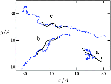
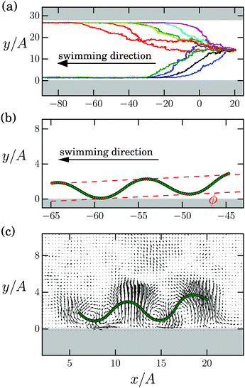
In the following we discuss the swimming velocity of the Taylor line as a function of the dimensionless persistence length p/Lc. Thermal fluctuations noticeably bend an elastic line on lengths comparable to the persistence length. So, in our case the Taylor line should have the form of a sine wave when p is much larger than its contour length Lc. In addition, the Taylor line performs translational and rotational Brownian motion as thermal fluctuations are inherently present in the MPCD fluid. All this is visible in Fig. 4. In case (a) with p/Lc = 1 the Taylor line is too floppy and the bending wave cannot develop. Only thermal motion of the center of mass occurs (blue line), reminiscent of a Brownian particle. In case (b) with p/Lc = 10 the bending wave is clearly visible, although still distorted by thermal fluctuations, and the Taylor line exhibits persistent motion. The Taylor line has a fully undistorted, sinusoidal contour in case (c) at p/Lc = 500. The trajectory of the center of mass shows directed swimming superimposed by Brownian motion. The total displacement over a complete simulation run is larger compared to (b) and the Taylor line has reached its maximum propulsion speed.To discuss directed swimming more quantitatively, we introduce the swimming velocity v∥ = d![[r with combining right harpoon above (vector)]](https://www.rsc.org/images/entities/i_char_0072_20d1.gif) ·
·![[e with combining right harpoon above (vector)]](https://www.rsc.org/images/entities/i_char_0065_20d1.gif) ∥/Δt, where we project the center-of-mass displacement d
∥/Δt, where we project the center-of-mass displacement d![[r with combining right harpoon above (vector)]](https://www.rsc.org/images/entities/i_char_0072_20d1.gif) during time Δt onto the mean direction of the Taylor line defined in eqn (12) and indicated in Fig. 3(b). We then define the stroke efficiency
during time Δt onto the mean direction of the Taylor line defined in eqn (12) and indicated in Fig. 3(b). We then define the stroke efficiency
 | (13) |
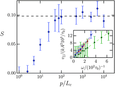
In Fig. 5 we plot the stroke efficiency S versus persistence length p/Lc. For p = Lc the stroke efficiency is approximately zero as already observed from the trajectory (a) in Fig. 4. The efficiency S increases nearly linearly in log(p/Lc) until at ca. p/Lc = 102 it reaches a plateau value. A linear fit gives the plateau value S0 = 0.098 typical for low Reynolds number swimmers. For example, for C. elegans studied in ref. 52 we estimate S = 0.12. In the following we always use the persistence length p/Lc = 5 × 10³ to be on the safe side.
Within resistive force theory, one derives for the swimming speed of the Taylor line in the limit of A ≪ λ:
 | (14) |
IV. Taylor line in a microchannel
In the following we present our simulation data of the Taylor line swimming in a microchannel and discuss it in detail.A. Swimming on a stable trajectory and under an acute angle at the channel wall
In Fig. 6(a) we show ten center-of-mass trajectories of identical Taylor lines in a wide microchannel with width d/A = 27.7. They all start in the middle of the channel and always swim in the negative x direction towards one of the channel walls. After an axial swimming distance of 80A, 92% of all our simulated Taylor lines have reached one of the channel walls (not all of the trajectories are shown here). We observe that in a very narrow channel with width d/A = 3.07, the swimming trajectory is not stable and the Taylor line switches from one wall to the other. However, already at d/A = 3.75 it stays at one channel wall. This occurs even though the walls are not further apart than four amplitudes. Stable swimming trajectories at channel walls have been observed in experiments and simulations of sperm cells and E. coli.22,23,38Fig. 6(b) shows that the Taylor line swims at an acute tilt angle along the channel wall. Earlier simulations of swimming sperm cells have attributed the attraction to the wall to a pusher-like flow field, which drags fluid in at the sides of the swimmer.38 Thereby, the sperm cells are hydrodynamically attracted by the wall. Additional flow at the free end of the flagellum pushes the tail of the sperm cell up. In Fig. 6(c) we confirm this picture. Below the wave crests fluid is strongly pulled towards the Taylor line, while fluid flow towards the wall below the wave troughs is much weaker. Hence, the Taylor line is attracted to the wall. In addition, fluid flow towards the wave crest at the front is stronger compared to the second wave crest, which obviously tilts the Taylor line as Fig. 6(b) demonstrates.
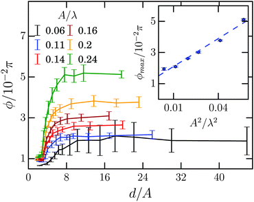
In order to investigate the tilt angle ϕ at the channel walls in more detail, in Fig. 7 we plot ϕ versus channel width for several amplitude-to-wavelength ratios A/λ. Each curve except for the smallest amplitude A starts with a small region of the channel width d/A ∈ [2,3], where the tilt angle is ca. 0.01π and hardly depends on d/A. Then, at the width d/A ≈ 3 the tilt angle increases and ultimately reaches a plateau value at d/A ≈ 8 meaning that the Taylor line does not interact with the other channel wall at widths d/A ≳ 8. The inset plots the plateau or maximum tilt angle ϕmaxversus A2/λ2. It is determined as the average of all tilt angles for d/A ≳ 8. The maximum tilt angle ϕmax needs to be an even function in A since −A only introduces a phase shift of π in the bending wave, which does not change the steady state of the Taylor line. Indeed, we can fit our data by
 | (15) |
B. Speed enhancement at the channel wall
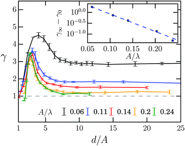
The swimming speed 〈vW〉 of the Taylor line along the channel wall is enhanced compared to the bulk value 〈v∥〉 and strongly depends on the channel width. To discuss this effect thoroughly, we define a speed enhancement factor| γ = 〈vW〉/〈v∥〉, | (16) |
The inset shows how γ∞ decreases with increasing wave amplitude A and reaches nearly one at A/λ = 0.24. This suggests the following interpretation. The Taylor line uses the no-slip condition of the fluid at the channel wall to push itself forward. This is more effective the closer the Taylor line swims at the wall, i.e., for small A. In contrast, with increasing A also the mean distance of the Taylor line from the wall increases and one expects to reach the bulk value of the swimming speed (γ∞ = 1) at large A. The dashed line in the inset is an exponential fit to γ∞ − γ0 = γ1![[thin space (1/6-em)]](https://www.rsc.org/images/entities/char_2009.gif) exp(−γ2A/λ). We find that γ0 = 1.08 deviates from the ideal large-amplitude value of one. This is due to a numerical artifact since for large A the MPCD fluid is no longer incompressible.82
exp(−γ2A/λ). We find that γ0 = 1.08 deviates from the ideal large-amplitude value of one. This is due to a numerical artifact since for large A the MPCD fluid is no longer incompressible.82
V. Taylor line in a cubic obstacle lattice
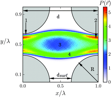
We now study the Taylor line swimming in a cubic lattice of obstacles with lattice constant d. Fig. 9 shows the cubic unit cell. The obstacles have a diameter 2R/λ, which we always refer to the wavelength λ = 21a0 of the Taylor line. By varying d and R, the Taylor line enters different swimming regimes, which we will discuss in detail in what follows.A. Dilute obstacle lattice
To define the dilute obstacle lattice, we introduce the width of the gap between two neighboring obstacles,| dsurf = d − 2R. | (17) |
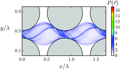
We illustrate the first case, dsurf > 2A, in Fig. 9, which shows the probability density P(![[r with combining right harpoon above (vector)]](https://www.rsc.org/images/entities/i_char_0072_20d1.gif) ) for all the beads of the Taylor line to visit a position
) for all the beads of the Taylor line to visit a position ![[r with combining right harpoon above (vector)]](https://www.rsc.org/images/entities/i_char_0072_20d1.gif) in the cubic unit cell. The probability density with the blue thin stripes shows that the Taylor line never leaves its lane. This is also true for other values of d/λ as long as the Taylor line cannot freely rotate in the space between the lattices. A closer inspection also shows a thin white region (1) around the obstacles, which the Taylor line never enters. Nevertheless, the probability of the beads for being in region (2) in the narrow gap between the obstacles is much higher than for being in region (3) between the four obstacles. We understand this as follows. The beads move up and down while moving with the Taylor line. In region (2) the beads reach their largest displacement equal to A and slow down to invert their velocity. So, they spend more time in region (2), which explains the high residence probability not only in (2) but also in region (4).
in the cubic unit cell. The probability density with the blue thin stripes shows that the Taylor line never leaves its lane. This is also true for other values of d/λ as long as the Taylor line cannot freely rotate in the space between the lattices. A closer inspection also shows a thin white region (1) around the obstacles, which the Taylor line never enters. Nevertheless, the probability of the beads for being in region (2) in the narrow gap between the obstacles is much higher than for being in region (3) between the four obstacles. We understand this as follows. The beads move up and down while moving with the Taylor line. In region (2) the beads reach their largest displacement equal to A and slow down to invert their velocity. So, they spend more time in region (2), which explains the high residence probability not only in (2) but also in region (4).
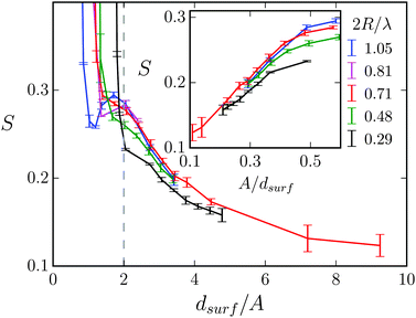
In Fig. 10 we plot the stroke efficiency as a function of dsurf/A for different 2R/λ. For dsurf/A > 2 the stroke efficiency ultimately is proportional to 1/dsurf as the inset demonstrates. In addition, at constant dsurf the efficiency S is roughly the same, stronger deviations only occur at the smallest 2R/λ = 0.29. This means S is mainly determined by the gap width, through which the Taylor line has to move when A is kept constant. For dsurf < 2A the Taylor line has to squeeze through the obstacle lattice. In the main plot of Fig. 10 one realizes a transition in all the curves, where S increases sharply. As we discuss in Section V.B, this is where the swimming Taylor line fits perfectly along one of the lattice directions and geometric swimming takes place.
B. Geometric swimming in a dense obstacle lattice
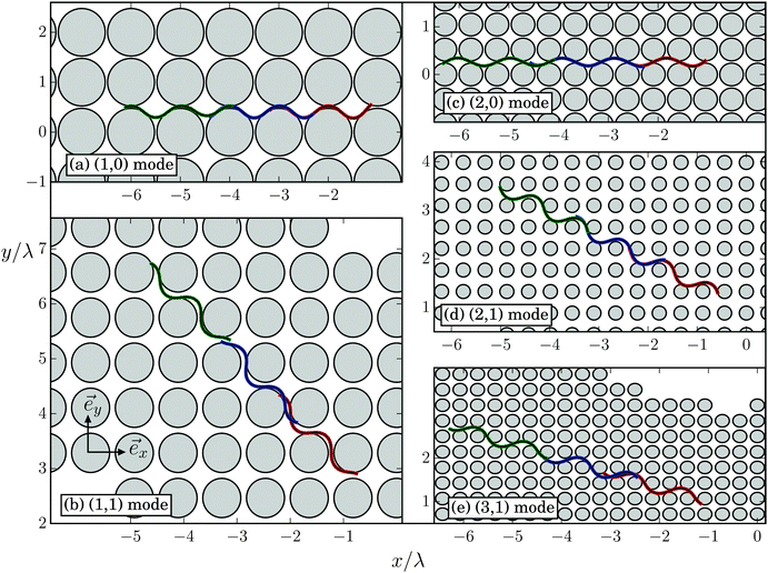
In dense obstacle lattices (dsurf < 2A) a new swimming regime occurs when the lattice constant d is appropriately tuned. Starting to swim in the horizontal direction (see Movie M1 in the ESI†), the Taylor line adjusts its swimming direction along a lattice direction with lattice vector![[g with combining right harpoon above (vector)]](https://www.rsc.org/images/entities/i_char_0067_20d1.gif) = d(m
= d(m![[e with combining right harpoon above (vector)]](https://www.rsc.org/images/entities/i_char_0065_20d1.gif) x + n
x + n![[e with combining right harpoon above (vector)]](https://www.rsc.org/images/entities/i_char_0065_20d1.gif) y), which defines the swimming mode (m,n). We call this regime geometrical swimming. Fig. 11 shows a few examples each with three snaphots of the Taylor line in green, red, and blue, where the time difference between the snapshots is between T and 2T. Perfect geometrical swimming occurs when one wave train fits perfectly into the lattice meaning
y), which defines the swimming mode (m,n). We call this regime geometrical swimming. Fig. 11 shows a few examples each with three snaphots of the Taylor line in green, red, and blue, where the time difference between the snapshots is between T and 2T. Perfect geometrical swimming occurs when one wave train fits perfectly into the lattice meaning | (18) |
![[g with combining right harpoon above (vector)]](https://www.rsc.org/images/entities/i_char_0067_20d1.gif) |. The (2,1) mode in the Movie M1 (ESI†) is a good example for geometric swimming. Depending on radius R and amplitude A, the Taylor line also pushes against the obstacles. Obviously, for perfect geometrical swimming the swimming velocity v∥ and the phase velocity c have to be identical: v∥ = c. The Taylor line swims with an efficiency S = 1. It behaves like a corkscrew, which is twisted into a cork; after a full rotation the corkscrew has advanced by exactly one pitch. Differently speaking, the Taylor line converts the bending wave optimally into a net motion without any slip between the Taylor line and viscous fluid. However, geometrical swimming also occurs when the perfect swimming condition is only approximately fulfilled,
|. The (2,1) mode in the Movie M1 (ESI†) is a good example for geometric swimming. Depending on radius R and amplitude A, the Taylor line also pushes against the obstacles. Obviously, for perfect geometrical swimming the swimming velocity v∥ and the phase velocity c have to be identical: v∥ = c. The Taylor line swims with an efficiency S = 1. It behaves like a corkscrew, which is twisted into a cork; after a full rotation the corkscrew has advanced by exactly one pitch. Differently speaking, the Taylor line converts the bending wave optimally into a net motion without any slip between the Taylor line and viscous fluid. However, geometrical swimming also occurs when the perfect swimming condition is only approximately fulfilled,  . In this case, the Taylor line pushes against the obstacles and the swimming velocity deviates from c but can even achieve values larger than c. We discuss this in the following. Note that several of these swimming modes, in particular the (1,1) mode, have been observed in experiments for C. elegans in an obstacle lattice.52,53
In the geometric swimming regime, the swimming efficiency S = v∥/c can be rewritten in pure geometric quantities. Using v∥ = deffν and c = λν, we immediately arrive at
 | (19) |
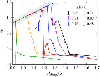 | ||
| Fig. 12 The stroke efficiency S = v∥/c for a Taylor line swimming predominantly in the diagonal direction, i.e., in the (1,1) mode. S is plotted versus the diagonal distance ddiag/λ between two obstacles for different obstacle diameters 2R/λ. The gray shaded area shows the geometrical swimming regime and the dashed line with slope one indicates the geometric-swimming relation S = ddiag/λ from eqn (19). | ||
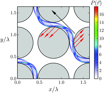
The regime of geometric swimming extends over a finite interval in ddiag. One recognizes that geometric swimming can also be implemented when ddiag = λ is not exactly fulfilled. Even swimming velocities larger than the wave velocity c (S > 1) are realized. Fig. 13 illustrates the mechanism for ddiag > λ. It shows the probability density P(![[r with combining right harpoon above (vector)]](https://www.rsc.org/images/entities/i_char_0072_20d1.gif) ) summed over all beads to occupy a position between the obstacles. P(
) summed over all beads to occupy a position between the obstacles. P(![[r with combining right harpoon above (vector)]](https://www.rsc.org/images/entities/i_char_0072_20d1.gif) ) reveals two sliding tracks of the Taylor line. A closer inspection shows that the head (nl0 ∈ [0,0.2Lc]) and middle (nl0 ∈ [0.2Lc,0.7Lc]) sections move on the “pushing” track. When the bending wave passes along the Taylor line, the Taylor line pushes against the obstacles (indicated by the red arrows), which helps it to swim faster than in the ideal case. This is nicely illustrated in Movie M1 in the ESI† for the (1,1) mode. The other track is mainly occupied by the tail section (nl0 ∈ [0.7Lc,Lc]) which does not contribute to the increased propulsion. In between the tracks there is a blurry area indicating that the part of the Taylor line between the middle and tail section has to transit from the pushing to the other track.
) reveals two sliding tracks of the Taylor line. A closer inspection shows that the head (nl0 ∈ [0,0.2Lc]) and middle (nl0 ∈ [0.2Lc,0.7Lc]) sections move on the “pushing” track. When the bending wave passes along the Taylor line, the Taylor line pushes against the obstacles (indicated by the red arrows), which helps it to swim faster than in the ideal case. This is nicely illustrated in Movie M1 in the ESI† for the (1,1) mode. The other track is mainly occupied by the tail section (nl0 ∈ [0.7Lc,Lc]) which does not contribute to the increased propulsion. In between the tracks there is a blurry area indicating that the part of the Taylor line between the middle and tail section has to transit from the pushing to the other track.
At larger obstacle diameters in Fig. 12 (red, blue, and purple line) the sharp decrease in S after the geometric swimming indicates a different transition. The Taylor line changes the direction and swims along the (1,0) direction since then the wavelength λ fits better to the spatial period, λ ≈ d. The local maximum in the red curve develops into a shoulder, which for the purple curve belongs to the (1,0) mode of geometrical swimming. Finally, for the black line (2R/λ = 0.86) geometric swimming along the (1,0) direction is more developed. In Fig. 14 we show the positional probability density of all beads of the Taylor line exactly at the local maximum of the red curve in Fig. 12. With d/λ = 0.87 the Taylor line is not in the geometric swimming regime. Even though the distribution is much more blurred than before, there is still a clear sinusoidal track visible. The Taylor line pushes against the obstacles, which helps it to move through the narrow gap. Finally, the red curve in Fig. 12 becomes flat when the Taylor line enters the dilute-lattice regime.
For lattice constants d well below λ and smaller obstacle diameters 2R, one also observes the higher modes (2,0), (2,1), and (3,1) visualized in Fig. 11. In Fig. 15 we summarize all our results by plotting S for the different swimming modes against the specific deff defined in eqn (18). The resulting master curve impressively illustrates the significance of geometrical swimming even reaching swimming velocities up to 20% larger than the ideal value from the phase velocity c. Thus, swimming in an obstacle lattice results in a new type of swimming compared to conventional locomotion at small Reynolds numbers, it resembles rather a corkscrew twisted into cork.
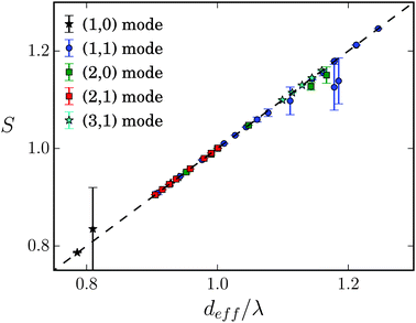 | ||
| Fig. 15 Stroke efficiency S versus effective distance deff/λ defined in eqn (18) for different swimming modes (m,n) and for different parameters. All data in the geometrical swimming regime collapse on one master curve. | ||
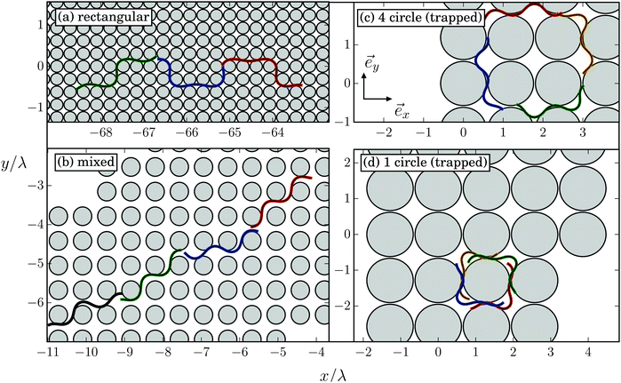
C. More complex trajectories
In Fig. 16 we show examples of trajectories that do not show geometric swimming along a defined direction as discussed in Section V.B but exhibit more complex shapes. They are also nicely illustrated in Movie M2 of the ESI.† Depending on the specific values for lattice constant d/λ and obstacle diameter 2R/λ, we can identify trajectories of different types. They either define new swimming modes [Fig. 16(a), (c) and (d)] or combine two geometric-swimming modes [Fig. 16(b)]. In Fig. 16(a) the obstacle lattice is so dense that the Taylor line cannot develop geometric swimming. Instead, it swims alternatively along the horizontal and vertical directions for four or two lattice constants, respectively, which results in a trajectory of rectangular shape. Fig. 16(b) shows the Taylor line while it switches its running mode between the (1,1) and (3,1) swimming directions (see also Movie M2, ESI†).A new trajectory type occurs when both the obstacle diameter 2R/λ and the lattice constant d/λ roughly agree with the wavelength (see also Movie M2, ESI†). In this case, after some transient regime the Taylor line is trapped and swims around a square of the same four obstacles [trapped circle mode in Fig. 16(c)] or around a single obstacle [trapped circle mode in Fig. 16(d)].
D. Variation of the length of the Taylor line
In Fig. 17 we plot the stroke efficiency S versus diagonal obstacle distance ddiag for different lengths L/λ of the Taylor line. We keep the wavelength and the obstacle radius constant. For L/λ = 0.5 the Taylor line hardly swims persistently, neither when it is strongly confined by the obstacles (ddiag/λ < 1.3) nor when it does not touch the obstacles at all (ddiag/λ > 1.3). This is nicely illustrated in Movie M3 (ESI†). For L/λ = 2 and 3 the Taylor lines first are clearly in the geometric-swimming regime along the (1,1) direction. The strong decrease of S at around ddiag/λ = 1.2 indicates the transition to swimming along the (1,0) direction. Right at the deep minimum of the red curve (L/λ = 2) the Taylor line gets more or less stuck before it enters the (1,0) swimming direction. At ca. ddiag/λ > 1.4 the obstacles are sufficiently apart from each other and the Taylor line does not push against them anymore.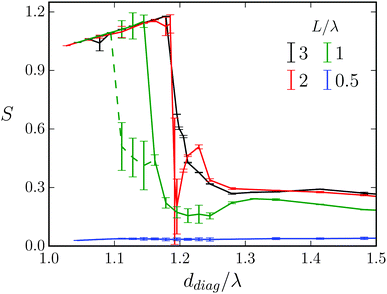 | ||
| Fig. 17 Stroke efficiency S versus diagonal distance ddiag/λ for different lengths L/λ of the Taylor line at wavelength λ = 21a0 and obstacle radius R/λ = 0.71. | ||
At length L/λ = 1 and ca. ddiag/λ = 1.1 a new feature occurs. The Taylor line switches between geometric swimming along the (1,1) and (1,0) directions. This is illustrated by the two branches of the green curve in Fig. 17 and in Movie M4 (ESI†) for ddiag/λ = 1.13. In the following broad minimum of the green curve (1.17 < ddiag/λ < 1.25), the Taylor line exhibits some stick-slip motion. It first pushes frequently against one obstacle and then swims more or less continuously for one lattice constant (see Movie M4, ESI† for ddiag/λ = 1.2). Again, at ddiag/λ > 1.4 the Taylor line does not push anymore against the obstacles while swimming.
VI. Summary and conclusions
We have implemented an undulatory Taylor line in a Newtonian fluid using the method of multi-particle collision dynamics and a sinusoidal bending wave running along the Taylor line. We have calibrated the parameters such that its persistence length is much larger than the contour length in order to observe regular undulatory shape changes and directed swimming.In microchannels the Taylor line swims to one channel wall. Swimming speed is enhanced due to hydrodynamic interactions and the Taylor line is oriented with an acute tilt angle at the wall similar to simulations of sperm cells.38 The acute angle can be understood by monitoring the initiated flow fields. In wide channels the tilt angle increases quadratically with the amplitude A of the bending wave, while the speed enhancement decreases exponentially with increasing A since the Taylor line swims, on average, further away from the wall. In narrow channels the swimming speed has a maximum at roughly d/A ≈ 3. The Taylor line uses the no-slip condition of the fluid at the walls to effectively push itself forward.
In a dilute obstacle lattice swimming speed is also enhanced due to hydrodynamic interactions with the obstacles. In the dense obstacle lattice we could reproduce the geometrical swimming observed in the case of C. elegans52,53 even though we did not consider any finite extension of the Taylor line. In addition, we found more complex swimming modes, which occur due to the strong confinement between the obstacles. In the geometrical swimming regime the Taylor line strongly interacts with the obstacles and swims with a speed close to the phase velocity of the bending wave, thus much more efficiently than in a pure bulk fluid. Geometrical swimming occurs when the wavelength of the Taylor line fits into the lattice along one specific direction. Thus, the swimming efficiencies of various geometrical swimming modes, plotted versus the ratio deff/λ of the effective obstacle distance and undulation wavelength, all collapse on the same master curve. Increasing deff/λ beyond one, even swimming speeds larger than the phase velocity of the bending wave occur but ultimately the Taylor line enters a different swimming mode. Thus, one can control the swimming direction of undulatory microorganisms by tuning the lattice constant of an obstacle lattice. This might be used for a microfluidic sorting device.
The concept of geometrical swimming goes back to Berg and Turner in order to explain the enhanced swimming of helical bacteria in polymer networks of viscoelastic fluids.48 Further studies on the undulatory Taylor line should investigate the enhanced swimming speed in more disordered obstacle suspensions and when the obstacles are allowed to move, which models more realistic environments such as blood. In both cases we expect the principle of geometric swimming to be applicable. However, the classification of a unique swimming mode with index (m,n), indicating the swimming direction, will no longer be possible. Instead, for fixed obstacles the Taylor line might switch between different modes, according to the local environment, but also become trapped while exploring possible swimming directions. All this will crucially depend on the size, polydispersity, and density of the obstacles. On sufficiently large length scales the swimmer then enters a diffusive motion. In a fluid with movable obstacles, the Taylor line is able to create a favorable environment by pushing the obstacles around. However, the swimming speed will be smaller than the ideal value given by the phase velocity c, since the movable obstacles give less resistance to the pushing Taylor line compared to fixed obstacles. All these considerations should be checked by further detailed simulations. By studying the principle of geometric swimming in the ideal case, this paper provides a guiding principle for understanding swimming in more complex environments.
Appendix A: calibration of parameters
We calibrate the amplitude A and wavelength λ of the Taylor line by varying the number of beads N and the curvature parameter b. The parameters used in this article are summarized in Table 1. The contour length is calculated using eqn (7).| N | b | λ/a0 | A/a0 |
|---|---|---|---|
| 88 | 0.105 | 21.02 | 1.26 |
| 94 | 0.168 | 21.02 | 2.23 |
| 97 | 0.18725 | 20.99 | 2.60 |
| 100 | 0.06 | 24.40 | 0.94 |
| 100 | 0.15 | 22.59 | 2.27 |
| 100 | 0.2 | 20.99 | 2.93 |
| 105 | 0.2162 | 20.98 | 3.43 |
| 125 | 0.24 | 21.04 | 5.02 |
Acknowledgements
We acknowledge helpful discussions with C. Prohm, J. Blaschke, and A. Zöttl. This research was funded by grants from DFG through the research training group GRK 1558, project STA 352/9, and within the priority program SPP 1726 ‘Microswimmers – from Single Particle Motion to Collective Behaviour’ (STA 352/11).References
- E. Lauga and T. R. Powers, Rep. Prog. Phys., 2009, 72, 096601 CrossRef.
- E. M. Purcell, Am. J. Phys., 1977, 45, 3 CrossRef.
- J. Lighthill, SIAM Rev., 1976, 18, 161 CrossRef.
- S. Suarez and A. A. Pacey, Hum. Reprod. Update, 2006, 12, 23 CrossRef CAS PubMed.
- I. R. Gibbons, J. Cell Biol., 1981, 91, 107s CrossRef CAS PubMed.
- H. C. Berg, Bacterial motility: handedness and symmetry, John Wiley & Sons, Ltd, 1991, pp. 58–72 Search PubMed.
- H. C. Berg, E. coli in Motion, Springer Science & Business Media, 2008 Search PubMed.
- R. Vogel and H. Stark, Phys. Rev. Lett., 2013, 110, 158104 CrossRef PubMed.
- T. C. Adhyapak and H. Stark, Phys. Rev. E: Stat., Nonlinear, Soft Matter Phys., 2015, 92, 052701 CrossRef PubMed.
- J. Hu, M. Yang, G. Gompper and R. G. Winkler, Soft Matter, 2015, 11, 7867 RSC.
- N. Heddergott, T. Krueger, S. Babu, A. Wei, E. Stellamanns, S. Uppaluri, T. Pfohl, H. Stark and M. Engstler, PLoS Pathog., 2012, 8, e1003023 CAS.
- R. S. Berman, O. Kenneth, J. Sznitman and A. M. Leshansky, New J. Phys., 2013, 15, 075022 CrossRef.
- A. Bilbao, E. Wajnryb, S. A. Vanapalli and J. Blawzdziewicz, Phys. Fluids, 2013, 25, 081902 CrossRef.
- G. Taylor, J. R. Soc., Interface, 1951, 209, 447 Search PubMed.
- G. Taylor, Proc. R. Soc. A, 1959, 253, 313 CrossRef.
- G. J. Elfring and E. Lauga, Phys. Rev. Lett., 2009, 103, 088101 CrossRef PubMed.
- T. D. Montenegro-Johnson and E. Lauga, Phys. Rev. E: Stat., Nonlinear, Soft Matter Phys., 2014, 89, 060701 CrossRef PubMed.
- R. Dreyfus, J. Baudry and H. Stone, Eur. Phys. J. B, 2005, 47, 161 CrossRef CAS.
- E. Gauger and H. Stark, Phys. Rev. E: Stat., Nonlinear, Soft Matter Phys., 2006, 74, 021907 CrossRef PubMed.
- R. Zargar, A. Najafi and M. Miri, Phys. Rev. E: Stat., Nonlinear, Soft Matter Phys., 2009, 80, 026308 CrossRef PubMed.
- D. Crowdy, Int. J. Non Linear Mech., 2011, 46, 577 CrossRef.
- L. Rothschild, Nature, 1963, 198, 1221 CrossRef.
- A. P. Berke, L. Turner, H. C. Berg and E. Lauga, Phys. Rev. Lett., 2008, 101, 038102 CrossRef PubMed.
- Y. Or and R. M. Murray, Phys. Rev. E: Stat., Nonlinear, Soft Matter Phys., 2009, 79, 045302 CrossRef PubMed.
- J. Elgeti and G. Gompper, Europhys. Lett., 2009, 85, 38002 CrossRef.
- G. Li and J. X. Tang, Phys. Rev. Lett., 2009, 103, 078101 CrossRef PubMed.
- G. Li, J. Bensson, L. Nisimova, D. Munger, P. Mahautmr, J. X. Tang, M. R. Maxey and Y. V. Brun, Phys. Rev. E: Stat., Nonlinear, Soft Matter Phys., 2011, 84, 041932 CrossRef PubMed.
- K. Obuse and J.-L. Thiffeault, in Natural Locomotion in Fluids and on Surfaces, ed. S. Childress, A. Hosoi, W. W. Schultz and J. Wang, The IMA Volumes in Mathematics and its Applications, Springer, New York, 2012, vol. 155, pp. 197–206 Search PubMed.
- A. Zöttl and H. Stark, Phys. Rev. Lett., 2012, 108, 218104 CrossRef PubMed.
- A. Zöttl and H. Stark, Eur. Phys. J. E: Soft Matter Biol. Phys., 2013, 36, 4 CrossRef PubMed.
- J. Elgeti and G. Gompper, Europhys. Lett., 2013, 101, 48003 CrossRef CAS.
- G.-J. Li and A. M. Ardekani, Phys. Rev. E: Stat., Nonlinear, Soft Matter Phys., 2014, 90, 013010 CrossRef PubMed.
- S. E. Spagnolie and E. Lauga, J. Fluid Mech., 2012, 700, 105 CrossRef.
- S. Uppaluri, N. Heddergott, E. Stellamanns, S. Herminghaus, A. Zoettl, H. Stark, M. Engstler and T. Pfohl, Biophys. J., 2012, 103, 1162 CrossRef CAS PubMed.
- R. Rusconi, J. S. Guasto and R. Stocker, Nat. Phys., 2014, 10, 212 CrossRef CAS.
- E. Lauga, W. R. DiLuzio, G. M. Whitesides and H. A. Stone, Biophys. J., 2015, 90, 400 CrossRef PubMed.
- M. d. C. Lopez-Garcia, R. L. Monson, K. Haubert, M. B. Wheeler and D. J. Beebe, Biomed. Microdevices, 2008, 10, 709 CrossRef CAS PubMed.
- J. Elgeti, U. B. Kaupp and G. Gompper, Biophys. J., 2010, 99, 1018 CrossRef CAS PubMed.
- P. Denissenko, V. Kantsler, D. J. Smith and J. Kirkman-Brown, Proc. Natl. Acad. Sci. U. S. A., 2012, 109, 8007 CrossRef CAS PubMed.
- V. Kantsler, J. Dunkel and R. E. Goldstein, Biophys. J., 2014, 106, 210a CrossRef.
- K. Schaar, A. Zöttl and H. Stark, Phys. Rev. Lett., 2015, 115, 038101 CrossRef PubMed.
- R. Nosrati, A. Driouchi, C. M. Yip and D. Sinton, Nat. Commun., 2015, 6, 8703 CrossRef CAS PubMed.
- Y. Yang, J. Elgeti and G. Gompper, Phys. Rev. E: Stat., Nonlinear, Soft Matter Phys., 2008, 78, 061903 CrossRef PubMed.
- M. M. Mota, G. Pradel, J. P. Vanderberg, J. C. R. Hafalla, U. Frevert, R. S. Nussenzweig, V. Nussenzweig and A. Rodríguez, Science, 2001, 291, 141 CrossRef CAS PubMed.
- J. P. Vanderberg and U. Frevert, Int. J. Parasitol., 2004, 34, 991 CrossRef PubMed.
- M. Engstler, T. Pfohl, S. Herminghaus, M. Boshart, G. Wiegertjes, N. Heddergott and P. Overath, Cell, 2007, 131, 505 CrossRef CAS PubMed.
- W. R. Schneider and R. N. Doetsch, J. Bacteriol., 1974, 117, 696 CAS.
- H. C. Berg and L. Turner, Nature, 1979, 278, 349 CrossRef CAS PubMed.
- X. N. Shen and P. E. Arratia, Phys. Rev. Lett., 2011, 106, 208101 CrossRef CAS PubMed.
- B. Liu, R. T. Powers and K. S. Breuer, Proc. Natl. Acad. Sci. U. S. A., 2011, 108, 19516 CrossRef CAS PubMed.
- V. A. Martinez, J. Schwarz-Linek, M. Reufer, L. G. Wilson, A. N. Morozov and W. C. K. Poon, Proc. Natl. Acad. Sci. U. S. A., 2014, 111, 17771 CrossRef CAS PubMed.
- S. Park, H. Hwang, N. Seong-Won, F. Martinez, R. H. Austin and W. S. Ryu, PLoS One, 2008, 3, e2550 Search PubMed.
- T. Majmudar, E. E. Keaveny, J. Zhang and M. J. Shelley, J. R. Soc., Interface, 2012, 9, 1809 CrossRef PubMed.
- J. A. Voynow and B. K. Rubin, Chest, 2009, 135, 505 CrossRef CAS PubMed.
- M. E. V. Johansson, J. K. Gustafsson, K. E. Sjöberg, J. Petersson, L. Holm, H. Sjövall and G. C. Hansson, PLoS One, 2010, 5, e12238 Search PubMed.
- G. C. Hansson, Curr. Opin. Microbiol., 2012, 15, 57 CrossRef CAS PubMed.
- X. Druart, Reprod. Domest. Anim., 2012, 47, 348 CrossRef PubMed.
- J. Teran, L. Fauci and M. Shelley, Phys. Rev. Lett., 2010, 104, 038101 CrossRef PubMed.
- E. E. Riley and E. Lauga, Europhys. Lett., 2014, 108, 34003 CrossRef.
- E. Lauga, Phys. Fluids, 2007, 19, 083104 CrossRef.
- H. C. Fu, T. R. Powers and C. W. Wolgemuth, Phys. Rev. Lett., 2007, 99, 258101 CrossRef PubMed.
- H. C. Fu, C. W. Wolgemuth and T. R. Powers, Phys. Fluids, 2009, 21, 033102 CrossRef PubMed.
- G. Juarez, K. Lu, J. Sznitman and P. E. Arratia, Europhys. Lett., 2010, 92, 44002 CrossRef.
- S. Babu, C. Schmeltzer and H. Stark, Swimming at low Reynolds number: from sheets to African trypanosome, Notes on Numerical Fluid Mechanics and Multidisciplinary Design, Springer, Berlin Heidelberg, 2012, vol. 119, pp. 25–41 Search PubMed.
- S. Babu and H. Stark, New J. Phys., 2012, 14, 085012 CrossRef.
- D. Alizadehrad, T. Krueger, M. Engstler and H. Stark, PLoS Comput. Biol., 2015, 11, e1003967 Search PubMed.
- R. E. Wells and E. W. Merrill, J. Clin. Invest., 1962, 41, 1591 CrossRef PubMed.
- P. W. Rand, E. Lacombe, H. E. Hunt and W. H. Austin, J. Appl. Physiol., 1964, 19, 117 CAS.
- S. Jung, Phys. Fluids, 2010, 22, 031903 CrossRef.
- A. Battista, F. Frischknecht and U. S. Schwarz, Phys. Rev. E: Stat., Nonlinear, Soft Matter Phys., 2014, 90, 042720 CrossRef PubMed.
- S. Johari, V. Nock, M. M. Alkaisi and W. Wang, Lab Chip, 2013, 13, 1699 RSC.
- S. H. Holm, J. P. Beech, M. P. Barrett and J. O. Tegenfeldt, Lab Chip, 2011, 11, 1326 RSC.
- G. Gompper, T. Ihle, D. Kroll and R. Winkler, Adv. Polym. Sci., 2009, 221, 1–87 CAS.
- A. M. Leshansky, Phys. Rev. E: Stat., Nonlinear, Soft Matter Phys., 2009, 80, 051911 CrossRef CAS PubMed.
- A. Malevanets and R. Kapral, J. Chem. Phys., 2000, 112, 7260 CrossRef CAS.
- A. Malevanets and R. Kapral, J. Chem. Phys., 1999, 110, 8605 CrossRef CAS.
- H. Noguchi and G. Gompper, Phys. Rev. E: Stat., Nonlinear, Soft Matter Phys., 2008, 78, 016706 CrossRef PubMed.
- R. Kapral, Adv. Chem. Phys., 2008, 140, 89–146 CrossRef CAS.
- E. Allahyarov and G. Gompper, Phys. Rev. E: Stat., Nonlinear, Soft Matter Phys., 2002, 66, 036702 CrossRef CAS PubMed.
- D. S. Bolintineanu, J. Lechman, S. J. Plimpton and G. S. Grest, Phys. Rev. E: Stat., Nonlinear, Soft Matter Phys., 2012, 86, 066703 CrossRef PubMed.
- A. Lamura and G. Gompper, Eur. Phys. J. E: Soft Matter Biol. Phys., 2001, 9, 477 CrossRef PubMed.
- J. T. Padding and A. A. Louis, Phys. Rev. E: Stat., Nonlinear, Soft Matter Phys., 2006, 74, 031402 CrossRef CAS PubMed.
- D. A. P. Reid, H. Hildenbrandt, J. T. Padding and C. K. Hemelrijk, Phys. Rev. E: Stat., Nonlinear, Soft Matter Phys., 2012, 85, 021901 CrossRef PubMed.
- M. Peltomaki and G. Gompper, Soft Matter, 2013, 9, 8346 RSC.
- P. Kanehl and H. Stark, J. Chem. Phys., 2015, 142, 214901 CrossRef PubMed.
- T. Ihle and D. M. Kroll, Phys. Rev. E: Stat., Nonlinear, Soft Matter Phys., 2001, 63, 020201 CrossRef CAS PubMed.
- T. Ihle and D. M. Kroll, Phys. Rev. E: Stat., Nonlinear, Soft Matter Phys., 2003, 67, 066705 CrossRef CAS PubMed.
- A. Zöttl and H. Stark, Phys. Rev. Lett., 2014, 112, 118101 CrossRef PubMed.
- J. T. Padding, A. Wysocki, H. Löwen and A. A. Louis, J. Phys.: Condens. Matter, 2005, 17, S3393 CrossRef CAS.
- P. Nelson, Biological Physics, W.H. Freeman and Company, 2008 Search PubMed.
Footnote |
| † Electronic supplementary information (ESI) available. See DOI: 10.1039/c6sm01304j |
| This journal is © The Royal Society of Chemistry 2016 |

