Improved performances of a LiNi0.6Co0.15Mn0.25O2 cathode material with full concentration-gradient for lithium ion batteries

Zhonghui Sun ab, Dandan Wang ab, Yingying Fan ab, Liansheng Jiao abd, Fenghua Li ab, Tongshun Wu ab, Dongxue Han ab and Li Niu *abc
aState Key Laboratory of Electroanalytical Chemistry, c/o Engineering Laboratory for Modern Analytical Techniques, CAS Center for Excellence in Nanoscience, Changchun Institute of Applied Chemistry, Chinese Academy of Sciences, Changchun, 130022, P. R. China. E-mail: lniu@ciac.ac.cn; Fax: +86-431-526 2800
bUniversity of Chinese Academy of Sciences, Beijing, 100049, P. R. China
cSchool of Chemistry & Chemical Engineering, Linyi University, Linyi 276005, P. R. China
dDepartment of Chemistry, Hebei Normal University for Nationalities, Chengde 067000, P. R. China

Received 16th September 2016 , Accepted 26th October 2016

First published on 27th October 2016


Abstract

A novel high capacity cathode material with a full concentration-gradient (FCG) structure has been successfully synthesized by a modified hydroxide co-precipitation method. A continuous concentration change of Ni, Co, and Mn from the core LiNi0.8Co0.1Mn0.1O2 to the shell LiNi0.4Co0.2Mn0.4O2 in each particle with an average composition of LiNi0.6Co0.15Mn0.25O2 is confirmed by EDX and ICP, respectively. Charge–discharge tests demonstrate that the FCG cathode delivers a high specific capacity of 190 mA h g−1 at a current density of 0.05 mA cm−2, exceptional rate capacity (a high capacity of 125 mA h g−1 at an ultrafast rate of 10C-rate), and an ultralong cycle life up to 1000 cycles (capacity retention of 80% at 5C-rate), which is obviously superior to the conventional cathode LiNi0.6Co0.15Mn0.25O2. Meanwhile, the Mn-rich in the outer layer of the FCG cathode contributes to more excellent thermal stability than the conventional cathode LiNi0.6Co0.15Mn0.25O2.

1. Introduction

Lithium-ion batteries (LIBs) have been widely used in the field of consumer electronics, large-scale electric grid energy storage and automotive applications such as electric vehicles and hybrid electric vehicles.1–4 However, for the realization of the electrification of the automobile, high-capacity, ultrafast-charge, long cycle life, and thermal safety electrodes are more desirable. Cathode materials, as the main energy bottleneck of the lithium ion batteries, have been experienced extensive research during the past decades.5–10 In particular, Ni-rich layered oxide materials LiNi1−xyCoxMnyO2 (0 ≤ x ≤ 1, 0 ≤ y ≤ 1, 0 ≤ x + y ≤ 1, LNCM) have attracted much attention as a promising cathode material candidate for the next generation of lithium ion batteries due to their high capacity of ca. 200 mA h g−1 and lower cost than the commercial LiCoO2.11,12 Despite the prominent advantages, however, they encounter poor cycle life and poor thermal stability, especially at high cut-off voltage or high temperature environment, owing to loss of oxygen from the host structure, reacting with the electrolyte and the graphite anode to induce serious safety accidents. What is worse, Ni-rich cathodes with high concentration unstable Ni4+ at the high cut-off voltage tend to be reduced to form a stable and insulating NiO phase on the cathode/electrolyte interface, resulting in increased interfacial impedance and then accompanied with severe capacity fade.13–15 Therefore, Ni-rich cathodes still need more exploration prior to large scale applications.

To date, several methods have been proposed to improve the performances of the Ni-rich cathodes, including different synthesis methods,16–19 coating and doping and so on.20–25 Excitingly, Yang-Kook Sun et al. pioneeringly constructed the core–shell (CS) and full concentration gradient (FCG) cathode materials in recent years. It is found that these advanced cathode materials present better thermal stability and cycle performance than normal structured materials.13,14,26–29

Herein, we report a cathode material, LiNi0.6Co0.15Mn0.25O2, which is redesigned into a full concentration gradient structure, where Ni, Co and Mn concentration continuously changes from the core to the outer surface in each particle (denoted FCG-LNCM), in which Ni-rich LiNi0.8Co0.1Mn0.1O2 as core provides high capacity and LiNi0.4Co0.2Mn0.4O2 with higher Mn content as out protective layer ensures cycling and thermal stability. In addition, the gradual increase of the Co concentration from the particle center to the surface improves the electronic conductivity, contributing to high rate capability. However, to the best of our knowledge, there has been no report concerning the preparation of the FCG LiNi0.6Co0.15Mn0.25O2 cathode material. As anticipated, this FCG cathode material shows excellent cycle life, outstanding rate capacity and good thermal stability compared with conventional LiNi0.6Co0.15Mn0.25O2 (denoted CC-LNCM).

2. Experimental

Chemicals: nickel sulfate hexahydrate (NiSO4·6H2O), manganese sulfate monohydrate (MnSO4·H2O), cobalt sulfate heptahydrate (CoSO4·7H2O), sodium hydroxide (NaOH), and ammonium hydroxide (NH3·H2O) are of analytical grade and used as received without any purification process.

2.1 Synthesis of FCG LiNi0.6Co0.15Mn0.25O2 and CC LiNi0.6Co0.15Mn0.25O2

The FCG precursor was fabricated through a co-precipitation method in a continuously stirred tank reactor equipped with baffles (CSTR, capacity of 10 L), as shown in Fig. 1. Typically, 2 mol L−1 Mn-rich aqueous solution (Ni[thin space (1/6-em)]:[thin space (1/6-em)]Co[thin space (1/6-em)]:[thin space (1/6-em)]Mn = 4[thin space (1/6-em)]:[thin space (1/6-em)]2[thin space (1/6-em)]:[thin space (1/6-em)]4 in molar ratio) from tank 1 was slowly pumped into 2 mol L−1 Ni-rich aqueous solution (Ni[thin space (1/6-em)]:[thin space (1/6-em)]Co[thin space (1/6-em)]:[thin space (1/6-em)]Mn = 8[thin space (1/6-em)]:[thin space (1/6-em)]1[thin space (1/6-em)]:[thin space (1/6-em)]1 in molar ratio) in tank 2. Then, the homogenous mixture was fed into the CSTR under N2 atmosphere. To ensure the cathode material consistency and convenient for operation in the practical industrial production, 4 mol L−1 NaOH solution as precipitate agent and 2 mol L−1 NH3·H2O solution as chelating agent were mixed and pumped into the CSTR at 60 °C under the constant pH with vigorous mechanical agitation. The concentration, pH value, temperature and stirring speed of the reaction mixture were carefully monitored during the reaction process. At the initial stage of the reaction, Ni0.8Co0.1Mn0.1(OH)2 (the particle center) was first precipitated, and transition metal hydroxide with different composition gradually deposited onto the surface of the spherical Ni0.8Co0.1Mn0.1(OH)2 particles via co-precipitation process to eventually synthesize the full concentration gradient precursor Ni0.6Co0.15Mn0.25(OH)2. The conventional Ni0.6Co0.15Mn0.25(OH)2 was also prepared via a similar co-precipitation route. Both precursor powders were obtained through filtering, washing, and drying at 110 °C overnight. In each experiment, ca.290 g precursor powders can be obtained as shown in Fig. S1 (ESI). The obtained precursor powders were mixed with a stoichiometric LiOH·H2O (Li/(Ni + Co + Mn) = 1.05 in molar ratio). Then the resulting mixture was preheated at 480 °C for 5 h, and sintered at 850 °C for 10 h to obtain the FCG-LiNi0.6Co0.15Mn0.25O2 cathode material.
image file: c6ra23088a-f1.tif
Fig. 1 Schematic illustration of the synthesis of the FCG hydroxide precursors and the corresponding cathodes.

2.2 Material characterizations

The chemical compositions of precursors and the amounts of Ni, Co, and Mn element of both cathodes in electrolyte after high temperature storage (55 °C) are analyzed by inductively coupled plasma spectroscopy (ICP, 6000 Series, Thermo SCIENTIFIC). Powder X-ray diffraction (XRD, BRUKERD/MAX 2500V/PC) with Cu Kα radiation is used to characterize the crystalline phase of the prepared materials in the 2θ range of 10°–80° with a step size of 0.03°. The morphologies of the precursors and cathode materials are observed with field emission scanning electron microscope (SEM, Philips XL30) at an accelerating voltage of 10.0 kV. To determine the local composition variation of the FCG precursors and cathode materials, cross section of the particle is prepared by embedding the particles in an epoxy matrix and grinding them flat. Energy dispersive X-ray spectroscopy (EDX, TECNAI G2) with a detection limit of about 200 nm is used to analyze the chemical composition of precursors and cathodes. For differential scanning calorimetric (DSC) measurement, both of the half-cells are initially charged to 4.4 V and disassembled in the Ar-filled glove box. After the electrolyte was carefully removed from the surface of the electrode, the electrode materials were scraped from the current collector to collect the samples (3–5 mg). Measurements are carried out in a DSC 7 (PERKIN ELMER) with a temperature scan rate of 5 °C min−1.

2.3 Electrochemical measurements

The working electrodes are prepared by mixing 80% the prepared cathode materials with 10% acetylene black and 10% polyvinylidene (PVDF) in NMP. The obtained slurry is coated onto Al foil and dried at 120 °C for 12 h under vacuum followed by a roll-pressing. The electrode with active material loading is about 5.0 ± 0.5 mg cm−2. A glass microfiber filter from Whatman (934-AH, UK) is used as a separator. Pure lithium foil is used as the anode, and 1 M LiPF6 in the ethylene carbonate diethyl carbonate (1[thin space (1/6-em)]:[thin space (1/6-em)]1 in volume) as the electrolyte. The half-cells are assembled in an Ar-filled glove box with CR2032 coin cells. The cells are charged and discharged in the voltage range of 3.0–4.4 V (vs. Li+/Li) with constant current densities via a NEWARE battery test system (CT-3008) at room temperature (25 °C). Electrochemical impedance measurements are carried out by using a Solartron 1255 B frequency response analyzer (SolartronInc., UK) in the frequency range of 100 kHz to 10 mHz.

3. Results and discussion

3.1 Material characterization

ICP is used to determine the compositions of synthesized precursors, and the results are listed in Table S1 (ESI). From the ICP results, it can be confirmed that both of the precursors have approximate composition, Ni0.6Co0.15Mn0.25(OH)2.

Fig. 2 compares XRD patterns of the as-prepared FCG and conventional cathode LiNi0.6Co0.15Mn0.25O2. Both samples can be indexed with a typical layer structure based on the hexagonal α-NaFeO2 with a space group R[3 with combining macron]m without any impurity phases, where there is a clear splitting of the (006)/(102) and (108)/(110) pairs. Generally, the intensity ratio of I003/I104 represents undesirable cation mixing of materials. If the ratio is lower than 1.2, indicating some Ni2+ ions migrate to Li+ sites and block the channel for Li+ ion transport.30 The lattice parameters are calculated from XRD patterns and summarized in Table 1, and the ratio of I003/I104 of both cathodes are higher than 1.2, indicating that both cathodes owned an ordered layered structure.14


image file: c6ra23088a-f2.tif
Fig. 2 XRD patterns of the FCG and conventional cathode LiNi0.6Co0.15Mn0.25O2.
Table 1 Lattice parameters of the FCG LiNi0.6Co0.15Mn0.25O2 and CC LiNi0.6Co0.15Mn0.25O2
Sample a c Vol/Å I (003)/I(004)
FCG 2.8705 14.2318 101.692 1.3947
CC 2.8693 14.2298 101.689 1.3603


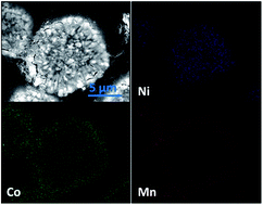
The SEM images, the distribution of Ni, Co, and Mn element of both precursors are shown in Fig. 3. The morphologies of both precursors show homogeneous spherical particles with average size of 12 µm in diameter, which are composed of the densely aggregated, needle-shape primary particles (Fig. 3a–d). Fig. 3e and f show the FCG hydroxide precursor has a continuous concentration variation from Ni0.8Co0.1Mn0.1(OH)2 (core) to Ni0.4Co0.2Mn0.4(OH)2 (surface). After lithiation, the spherical morphologies are well maintained as shown Fig. 4a–d, and the Ni-rich particle centre and Mn-rich outer surface are clearly seen from the SEM mapping images (Fig. 4e). However, after high temperature calcination, a slight inter-diffusion of Ni, Co and Mn element is observed, as confirmed by the slightly flattened slope in Fig. 4f. As a result, the Ni content at the center decreases to 71%, while the outer layer Ni content increases to 46%. For the same reason, the Co concentration increases from 11% to 14% at the center, while the Mn concentration at the surface decreases by 2%, eventually resulting in the center composition of LiNi0.71Co0.14Mn0.15O2 and the surface composition of LiNi0.46Co0.19Mn0.35O2. The phenomenon of the interdiffusion of Ni, Co, Mn during high temperature annealing is also observed by Jeff Dahn and coworkers in their recent studies.37,38


image file: c6ra23088a-f3.tif
Fig. 3 SEM images of low- and high-magnification of the FCG precursor (a, b), and conventional precursor (c, d); element mapping (e) and EDX compositional change of Ni, Co and Mn in the cross-section of the FCG precursor (f).

image file: c6ra23088a-f4.tif
Fig. 4 SEM images of low- and high-magnification of the FCG cathode (a, b), and conventional cathode (c, d); element mapping and EDX compositional change of Ni, Co and Mn in the cross-sectional of the FCG cathode (e, f).

3.2 Electrochemical and thermal properties

The synthesized FCG and conventional LiNi0.6Co0.15Mn0.25O2 material in 2032 coin-type half cells are electrochemically evaluated between 3.0 and 4.4 V versus Li/Li+ with constant current densities at 25 °C. Both electrodes deliver a high discharge capacity of 190 mA h g−1 for the FCG cathode and 185 mA h g−1 for the conventional cathode at a current density of 0.05 mA cm−2 (0.1C-rate) (Fig. 5a). Fig. 5b shows rate capacity of the FCG and conventional LiNi0.6Co0.15Mn0.25O2 electrode. As expected, the FCG electrode presents better rate capacity than conventional electrode at each current rate. Especially, a high capacity of 125 mA h g−1 can be delivered at 10C-rate, which is mainly attributed to good Li+ intercalation stability for the FCG electrode. Meanwhile, it can be clearly seen that conventional cathode LiNi0.6Co0.15Mn0.25O2 has a larger potential polarization than that of the FCG LiNi0.6Co0.15Mn0.25O2 cathode as shown in Fig. S2 and S3 (ESI).
image file: c6ra23088a-f5.tif
Fig. 5 (a) Initial charge–discharge curves, (b) rate capacity, and (c, d) differential capacity vs. voltage curves at 0.05 mA cm−2 of the CC and FCG LiNi0.6Co0.15Mn0.25O2.

Derivatives of the charge–discharge curves provide a valuable insight into the electrochemical reactions that occurred during cycling. As shown in Fig. 5c and d, both electrodes exhibit two oxidation peaks at about 3.64 V, 3.74 V and a reduction peak at about 3.72 V, during which the transition process is between the hexagonal phase (H1) and the monoclinic (M) phase.31,32 These peaks are associated with the Ni2+/Ni4+ and Co3+/Co4+ redox couples.15 Here, the appearance of the oxidation peak at around 3.64 V is the characteristic of Ni-rich cathodes.33 Note that voltage decay and shortening of the voltage plateau are very evident for the conventional electrode (Fig. 5c), whereas the operation voltage and plateau length are fairly constant with cycling for the FCG electrode demonstrating the good insertion and deintercalation reversibility of Li+ ions (Fig. 5d).

Both types of electrodes are also cycled at 0.5C-rate for 400 cycles and 5C-rate for 1000 cycles as shown in Fig. 6a and b. The FCG cathode shows much enhanced cycling performance over the conventional cathode with capacity retention of 85% at 0.5C-rate after 400 cycles and 80% at 5C-rate after 1000 cycles in a half-cell configuration. In contrast, the conventional cathode shows a rapid capacity fade, resulting in capacity retention of 72% at 0.5C-rate and 57% at 5C-rate. The improved cycling performance of the FCG cathode should be ascribed to the increased interface stability against the corrosive electrolyte by decreasing the Ni concentration and increasing the Mn concentration at the outer surface layer, which reduces reactivity with electrolyte by decreasing the specific surface area and thus suppressing the increase in interfacial impedance during cycling. In addition, the negligible occupation of Ni2+ in the Li layer for the FCG cathode is also favorable for the repetitive Li+ insertion and deintercalation, facilitating the excellent electrochemical performances.34


image file: c6ra23088a-f6.tif
Fig. 6 Cycling performance of the FCG and CC LiNi0.6Co0.15Mn0.25O2 at (a) 0.5C-rate, and (b) 5C-rate.

As shown in Fig. 7a–c, the spherical morphologies and concentration-gradient structure of the FCG cathode are well maintained even after 400 cycles. To further compare the structural stability of the FCG and conventional cathode, XRD tests were carried out and the results are shown in Fig. 7d and summarized in Table 2. The lattice parameters of the FCG cathode are almost identical compared to the pristine electrode, the clear peak splitting of the (006)/(102) and (108)/(110) pairs indicate that the well layered structure is maintained. In the contrary, the conventional cathode has a significantly weak peak intensity of I(003)/I(104) compared to that of the FCG cathode, indicating a deteriorated trend owing to the changes of crystal structure from Li+/Ni2+ mixing, as inferred by the severe occupation of Ni2+ in the Li layer resulting in the gradual declination of the capacity upon cycling. Based on the above discussions, the FCG cathode with high Mn content on the outer layer can contribute to excellent capacity retention and good structural stability during the ultralong cycling.


image file: c6ra23088a-f7.tif
Fig. 7 SEM images of (a) FCG, and (b) CC LiNi0.6Co0.15Mn0.25O2 after 400 cycle; (c) EDX compositional change from the center to the surface for the cycled FCG electrode; (d) XRD patterns of the 400th cycled FCG and CC LiNi0.6Co0.15Mn0.25O2 electrode; (e, f) EIS of the FCG and CC LiNi0.6Co0.15Mn0.25O2 electrode before and after 400 cycles.
Table 2 Lattice parameters of the FCG LiNi0.6Co0.15Mn0.25O2 and CC LiNi0.6Co0.15Mn0.25O2 after 400 cycles
Sample a c Volume/Å I (003)/I(004)
FCG 2.8685 14.2418 101.252 1.2507
CC 2.8623 14.2478 100.945 1.1813


To further understand the electrode reaction kinetics of the both samples, the EIS spectra are given in Fig. 7e and f. The solid dots indicate the experimental results and the solid lines were fitted by ZSimpWin software with proposed equivalent circuit model (inset of Fig. 7e and f). Rs is the solution resistance. Rsf and CPE1 are the resistance and the associated constant phase element of the surface film, respectively. Rct and CPE2 are the charge transfer resistance and constant phase element at the electrode/electrolyte interface, respectively. Zw is Warburg impedance. Apparently, the EIS spectra of both electrodes are almost overlapped before cycle. However, after 400 cycles, the Rsf and Rct of the CC LiNi0.6Co0.15Mn0.25O2 electrode are much larger than that of the FCG LiNi0.6Co0.15Mn0.25O2 electrode. Previous studies have confirmed that the increase of Rsf and Rct are mainly attributed to the surface degradation of the cathode caused by transition metal dissolution due to the electrolyte corrosion and the surface reconstruction exhibited a strong anisotropic characteristic and induced a phase transition from an R[3 with combining macron]m layered structure to an Fm[3 with combining macron]m rock-salt structure at the surface of LiNixMnxCo1−2xO2 particles.39,40

The concentration of Ni, Co, and Mn elements in the electrolyte is measured after different storage time at 55 °C. As shown in Table 3, the FCG cathode exhibits the lowest transition metal dissolution with storage time, whereas dissolution from the conventional cathode rapidly increases after two weeks. Based on the aforementioned analysis, the FCG cathode with high Mn content on the outer layer is beneficial to suppress Ni dissolution and guarantee good cycle stability during ultralong cycling.

Table 3 Amounts of dissolved Ni, Co, and Mn in electrolyte after charging the FCG and CC LiNi0.6Co0.15Mn0.25O2 electrode in a 2032 coin-type half-cell to 4.4 V vs. Li/Li+ at 55 °C
Storage time Ni/ppm Co/ppm Mn/ppm
FCG
1 week 26.31 13.54 27.12
2 weeks 30.52 15.75 30.47
4 weeks 52.23 41.86 47.29
[thin space (1/6-em)]
CC
1 week 37.89 16.68 37.57
2 weeks 49.45 24.35 43.35
4 weeks 98.83 82.73 97.58


The thermal stability of the cathode plays an important role in cell safety for the battery pack in EVs and PHEVs. To evaluate the thermal stability of the FCG and conventional cathode, the initially delithiated FCG and CC Li1−σNi0.6Co0.15Mn0.25O2 cathodes are analyzed by a differential scanning calorimetry (DSC).

As shown in Fig. 8, each delithiated electrode displays a main exothermic reaction at the high temperature above 260 °C. According to the previous reports,2,26,36 the exothermic reaction is mainly ascribed to oxygen release from the active material host structure, so that the crystal structure is subject to changes of the layer (R[3 with combining macron]m) to a spinel (Fd[3 with combining macron]m) structure while the temperature increases.35,36 The conventional Li1−σNi0.60Co0.15Mn0.25O2 cathode exhibits a large exothermic peak at a relatively temperature (262.4 °C). In contrast, the exothermic reaction temperature of the FCG electrode is much higher (273.6 °C) with a reduced heat generation, which the onset exothermal temperature was delayed by 11.2 °C. The improved thermal stability of the FCG cathode derives from the higher thermal stability of the outer layer composition of LiNi0.4Co0.2Mn0.4O2 in the FCG electrode, which possesses more excellent thermal stability at the highly delithiated state compared to the conventional cathode.


image file: c6ra23088a-f8.tif
Fig. 8 DSC profiles of the FCG and CC Li1−σNi0.6Co0.15Mn0.25O2 electrodes.

4. Conclusions

In summary, we report a full concentration-gradient cathode material via a modified co-precipitation method followed by a high temperature lithiation process. The Ni, Co and Mn elements exhibit a continuous concentration-gradient change within a single particle, where the Ni-rich core provides high capacity, and the high Mn content on the surface improves the thermal stability and diminishes the reactivity with the corrosive electrolyte, while the gradual increase of Co content from the particle center to the surface improves the electronic conductivity, yielding an excellent rate capacity (125 mA h g−1 at 10C-rate). In half-cell test, the FCG LiNi0.6Co0.15Mn0.25O2 cathode shows outstanding cycling life. Therefore, the FCG cathode material should be applied to advanced lithium-ion batteries with ultrafast charge, high capacity, long calendar life, and outstanding safety. We consider that this novel strategy would be helpful to the rational design and development of other high capacity cathode materials based on this advanced concept of the full concentration-gradient structure.

Acknowledgements

We thank Dr Xing-Long Wu (NENU) for useful discussions. The authors are most grateful to the NSFC, China (21225524, 21505127 and 21501169), the Department of Science and Techniques of Jilin Province (20150203002YY, 20150201001GX and 20150204065GX) and special funds for the Construction of Taishan Scholars (No. ts201511058).

References

  1. Y. K. Sun, Z. H. Chen, H. J. Noh, D. J. Lee, H. G. Jung, Y. Ren, S. Wang, C. S. Yoon, S. T. Myung and K. Amine, Nat. Mater., 2012, 11, 942–947 CrossRef CAS PubMed.
  2. Y. K. Sun, S. T. Myung, B. C. Park, J. Prakash, I. Belharouak and K. Amine, Nat. Mater., 2009, 8, 320–324 CrossRef CAS PubMed.
  3. L. Riekehr, J. L. Liu, B. Schwarz, F. Sigel, I. Kerkamm, Y. Y. Xia and H. Ehrenberg, J. Power Sources, 2016, 306, 135–147 CrossRef CAS.
  4. E. S. Lee, A. Huq, H. Y Chang and A. Manthiram, Chem. Mater., 2012, 24, 600–612 CrossRef CAS.
  5. J. M. Zheng, W. H. Kan and A. Manthiram, ACS Appl. Mater. Interfaces, 2015, 7, 6926–6934 CAS.
  6. E. S. Lee and A. Manthiram, J. Mater. Chem. A, 2013, 1, 3118–3126 CAS.
  7. S. K. Martha, J. Nanda, G. M. Veith and N. J. Dudney, J. Power Sources, 2012, 216, 179–186 CrossRef CAS.
  8. P. He, H. Yu, D. Li and H. Zhou, J. Mater. Chem., 2012, 22, 3680–3695 RSC.
  9. M. H. Kim, H. S. Shin, D. Shin and Y. K. Sun, J. Power Sources, 2006, 159, 1328–1333 CrossRef CAS.
  10. Y. K. Sun, D. H. Kim, H. G. Jung, S. T. Myung and K. Amine, Electrochim. Acta, 2010, 55, 8621–8627 CrossRef CAS.
  11. K. J. Kim, Y. N. Jo, W. J. Lee, T. Subburaj, K. Prasanna and C. W. Lee, J. Power Sources, 2014, 268, 349–355 CrossRef CAS.
  12. S. W. Zhong, M. Z. Lai, W. L. Yao and Z. C. Li, Electrochim. Acta, 2016, 212, 343–351 CrossRef CAS.
  13. B. B. Lim, S. J. Yoon, K. J. Park, C. S. Yoon, S. J. Kim, J. J. Lee and Y. K. Sun, Adv. Funct. Mater., 2015, 25, 4673–4680 CrossRef CAS.
  14. K. J. Park, B. B. Lim, M. H. Choi, H. G. Jung, Y. K. Sun, M. Haro, N. Vicente, J. Bisquert and G. G. Belmonte, J. Mater. Chem. A, 2015, 3, 22183–22190 CAS.
  15. P. Y. Hou, L. Q. Zhang and X. P. Gao, J. Mater. Chem. A, 2014, 2, 17130–17138 CAS.
  16. T. H. Cho, S. M. Park, M. Yoshi, T. Hirai and Y. Hideshima, J. Power Sources, 2005, 142, 306–312 CrossRef CAS.
  17. N. Yabuuchi, Y. Koyam, N. Nakayam and T. Ohzuku, J. Electrochem. Soc., 2005, 152, A1434–A1440 CrossRef CAS.
  18. D. C. Li, T. Muta, L. Q. Zhang, M. Yoshio and H. Noguchi, J. Power Sources, 2004, 132, 50–155 CrossRef.
  19. K. M. Nam, H. J. Kim, D. H. Kang, Y. S. Kim and S. W. Song, Green Chem., 2015, 17, 1127–1135 RSC.
  20. G. H. Kim, M. H. Kim, S. T. Myung and Y. K. Sun, J. Power Sources, 2005, 146, 602–605 CrossRef CAS.
  21. G. Y. Li, Z. J. Zhang, R. N. Wang, Z. L. Huang, Z. C. Zuo and H. H. Zhou, Electrochim. Acta, 2016, 212, 399–407 CrossRef CAS.
  22. S. Madhavi, G. V. Subba Rao, B. V. R. Chowdari and Y. Li, J. Power Sources, 2001, 93, 156–162 CrossRef CAS.
  23. J. Liu, B. R. Jayan and A. Manthiram, J. Phys. Chem. C, 2010, 114, 9528–9533 CAS.
  24. P. Yue, Z. X. Wang, H. J. Guo, X. H. Xiong and X. H. Li, Electrochim. Acta, 2013, 92, 1–8 CrossRef CAS.
  25. H. Ming, Y. R. Yan, J. Ming, J. Adkins, X. W. Li, Q. Zhou and J. W. Zheng, Electrochim. Acta, 2014, 120, 390–397 CrossRef CAS.
  26. Y. K. Sun, S. T. Myung, M. H. Kim, J. Prakash and K. Amine, J. Am. Chem. Soc., 2005, 127, 13411–13418 CrossRef CAS PubMed.
  27. Y. K. Sun, B. R. Lee, H. J. Noh, H. M. Wu, S. T. Myung and K. Amine, J. Mater. Chem., 2011, 21, 10108–10112 RSC.
  28. H. J. Noh, Z. H. Chen, C. S. Yoon, J. Lu, K. Amine and Y. K. Sun, Chem. Mater., 2013, 25, 2109–2115 CrossRef CAS.
  29. M. H. Lee, Y. J. Kang, S. T. Myung and Y. K. Sun, Electrochim. Acta, 2004, 50, 939–948 CrossRef CAS.
  30. H. Kim, M. G. Kim, H. Y. Jeong, H. Nam and J. Cho, Nano Lett., 2015, 15, 2111–2119 CrossRef CAS PubMed.
  31. M. E. Arroyo y de Dompablo, A. Van der Ven and G. Ceder, Phys. Rev. B: Condens. Matter Mater. Phys., 2002, 66, 0641121–0641129 CrossRef.
  32. H. J. Noh, S. Youn, C. S. Yoon and Y. K. Sun, J. Power Sources, 2013, 233, 121–130 CrossRef CAS.
  33. Y. Li, R. Xu, Y. Ren, J. Lu, H. M. Wu, L. F. Wang, D. J. Miller, Y. K. Sun, K. Amine and Z. H. Chen, Nano Energy, 2016, 19, 522–531 CrossRef CAS.
  34. J. W. Ju, E. J. Lee, C. S. Yoon, S. T. Myung and Y. K. Sun, J. Phys. Chem. C, 2014, 118, 175–182 CAS.
  35. S. J. Yoon, S. T. Myung, H. J. Noh, J. Lu, K. Amine and Y. K. Sun, ChemSusChem, 2014, 7, 3295–3303 CrossRef CAS PubMed.
  36. H. J. Noh, Z. H. Chen, C. S. Yoon, J. Lu, K. Amine and Y. K. Sun, Chem. Mater., 2013, 25, 2109–2115 CrossRef CAS.
  37. J. Li, R. Doig, J. Camardese, K. Plucknett and J. R. Dahn, Chem. Mater., 2015, 27, 7765–7773 CrossRef CAS.
  38. J. Li, J. Camardese, R. Shunmugasundaram, S. Glazier, Z. H. Lu and J. R. Dahn, Chem. Mater., 2015, 27, 3366–3377 CrossRef CAS.
  39. F. Lin, I. M. Markus, D. Nordlund, T. C. Weng, M. D. Asta, H. L. Xin and M. M. Doeff, Nat. Commun., 2014, 5, 3529,  DOI:10.1038/ncomms4529.
  40. F. Lin, D. Nordlund, I. M. Markus, T. C. Weng, H. L. Xin and M. M. Doeff, Energy Environ. Sci., 2014, 7, 3077–3085 CAS.

Footnote

Electronic supplementary information (ESI) available. See DOI: 10.1039/c6ra23088a

This journal is © The Royal Society of Chemistry 2016