Cellulose nanofibril reinforced silica aerogels: optimization of the preparation process evaluated by a response surface methodology†
Jingjing Fuab,
Chunxia Hea,
Jingda Huangc,
Zhilin Chenc and
Siqun Wang*bc
aCollege of Engineering, Nanjing Agricultural University, Nanjing, 210031, China
bCenter for Renewable Carbon, University of Tennessee, Knoxville, TN 37996, USA
cResearch Institute of Wood Industry, Chinese Academy of Forestry, Beijing, 100091, China. E-mail: swang@utk.edu
First published on 13th October 2016
Abstract
Cellulose nanofibrils (CNF) were used to reinforce silica aerogels, aiming to ameliorate the aerogels' inherent brittleness. The CNF-reinforced silica aerogels were prepared through the elaboration of silica particles interpenetrated with a nanocellulosic network structure by immersion of the CNF aerogels into a silica solution in a two-step sol–gel process (first, hydrolysis of tetraethyl orthosilicate (TEOS) and second, condensation under alkaline conditions). The relationships among the silica content, the density, and the compressive properties of the composite aerogels were investigated. A response surface methodology (RSM) was applied to optimize the preparation process (CNF concentration, TEOS concentration, pH value of condensation process and immersion time) with the target being to synthesize a desired aerogel with improved mechanical properties. The results show that density can be seen as a function of the silica content, and that the two had a positive dependent relationship. The compressive properties were also greatly affected by the silica loading into the cellulosic scaffold. The composite aerogel displayed high compressive properties at 40–50 wt% silica particles. The optimal condition would be a CNF aerogel of 5% solid content immersed into a 2.5 mol L−1 TEOS sol with condensation at pH value of 10 for 10 min. The compressive modulus (6.57 MPa) and compressive strength (1.37 MPa) of the composite aerogel greatly exceeded those of the pure silica aerogel, without substantial increases in density (0.1 g cm−3). The composite aerogel also had good insulation properties (thermal conductivity was 0.0226 W m−1 K−1) and hydrophobicity (contact angle 152.1°) and thus can be considered as a multi-functional aerogel capable of applications in a wide variety of areas.
Introduction
Aerogels, especially silica aerogels, are among the lightest known mesoporous solids, well recognized for their superinsulating properties, low dielectric constant, large specific surface area, and low density.1–4 However, the weak mechanical properties of their inorganic network structure narrow their fields of application.5,6 Therefore, the development of a composite aerogel yields significant improvements in the brittle, fragile mechanical properties of traditional silica aerogels and lowers their high production cost. The advantage of composite materials is that they usually exhibit the best qualities of their component parts; in addition, they exhibit some qualities that neither constituent possesses on its own. The process of incorporating individualized micro- or nano-dimensional objects as a secondary phase into the silica system or interpenetrating a fibrous network on the support skeleton of silica particles has encouraged the widespread application of silica aerogels. For example, in the aerospace field, White et al.7 at NASA's Ames Research Center synthesized ceramic fiber-reinforced silica aerogels that could be used as insulating materials. Some composites comprising silica aerogel and other materials are under development for use in thermoelectric devices in space exploration mission design,8 such as insulated extra-vehicular activity (EVA) suits9 or the baseline insulation materials of inflatable decelerators for entry, descent, and landing (EDL) applications.10 An increasing number of industrial applications has been found, from the development of long-lasting fragrances to the protection of materials surfaces against bacterial attack, or targeting of diseases, or film form,11,12 the use of porous and functionally modified silica aerogels have taken on the stage. Furthermore, composite aerogels can now also be used as high-efficiency catalysts,13 electrodes,14 fire shields15 and adsorbents16 that perform better than conventional silica aerogels.Some studies about the mechanical properties of enhanced silica aerogels have been reported, with their secondary phase being based on materials ranging from poly(ethyl acrylate)17 to non-woven polypropylene,18 glass fiber,19 mullite fiber,20 aluminum silicate fiber,21 carbon fiber,22 and so on. Very recently, cellulose or bacterial cellulose23 has been proposed as a reinforcing phase for silica aerogels. As a biocompatible and biodegradable polymer, cellulose is abundantly available as a primary reinforcement for load bearing.24 With varied hydrogen-bonding network and molecular orientation, cellulose has been identified with six interconvertible polymorphs, namely, I, II, IIII, IIIII, IVI, and IVII, depending on the respective source, method of extraction, or treatment.25 Cellulose I and cellulose II are the first and second most extensively studied allomorphs. Native cellulose has been thought to have one crystal structure, cellulose I. It could be used as template material with good mechanical properties, but native cellulose aerogel is unstable when immerse into water.26 The development of aerocellulose based on cellulose II is relatively mature, it could be obtained by chemical regeneration or mercerization.25 No matter cellulose I or cellulose II, there has been increasing interest in development of nanocomposites based on nanocellulosic materials.27 Cellulose nanofibrils (CNF) are of particular interest. CNFs consist of long, flexible, interconnected fibers with hierarchical structure and remarkable mechanical properties; they are a promising potential structural reinforcement material for silica aerogel-based composites. Up to now, there are some known on making porous silica-nanofibrillated cellulose aerogels through supercritical CO2 drying.28–30 It is known that silica gel dried under ambient pressure drying (APD) would “explode” into small pieces due to the internal stresses developed during drying, namely, capillary pressure.31 However, in this work, we combined low risky and low cost method: freezing drying and APD method to obtain monolithic silica–CNF composite aerogel.
In previous work, we have synthesized a composite aerogel by immersing the CNF aerogel into the silica sol to form an interpenetrating silica network inside the cellulosic scaffold,32 which are like pearl necklace structures. The first work demonstrating pearl necklace formation of silica along the fibrils of cellulose was Liu et al.33 We found that the preparation condition and formulation play a vital role in determining the properties of composite aerogels. We also found that the yield of silica in the composite aerogel could determine the overall performance of the aerogels. In this research, the response surface methodology (RSM) was applied to elucidate the effect of the preparation parameters (i.e., CNF concentration, TEOS concentration, pH value of the condensation process and immersion time) on the physical properties (i.e., silica content and density) and mechanical properties. To optimize the parameters, RSM was used an effective statistical modeling tool, especially in cases where many factors are involved and varied simultaneously.34 In this study, RSM based on Box–Behnken design (BBD) was adopted through Design Expert software. BBD is a second-order multivariate design technique based on three-level incomplete factorial designs; it has received widespread attention for the evaluation of critical experimental conditions.35 The aim of this study is to tackle the problem of silica aerogels' brittleness by introducing silica particles into the cellulose network structure; the relationships among the silica content, the density and the compressive properties were also investigated. Finally, the optimal process condition and formulation were achieved using BBD optimization, yielding the desired CNF–silica aerogel with improved mechanical properties for increased potential application of the composite aerogel.
Experimental
Materials
Tetraethyl orthosilicate (TEOS, 98% purity), hydrochloric acid (HCl, 12.1 M), ammonium hydroxide (NH4OH, 1.0 M), ethanol (anhydrous, histological), n-hexane (≥95%, environmental grade), trimethylchlorosilane (TMCS, 98%) were purchased from Fisher Scientific (USA) and used as received. Cellulose nanofibrils (CNF, solids 2.95%) were purchased from The University of Maine Process Development Center (Orono, ME, USA), the CNF was prepared mechanically using a pilot-scale double disk refiner to defibrillate a bleached softwood kraft pulp. Crosslinker Kymene™ resin (polyamide-epichlorohydrin resin, Ashland Hercules Inc., USA) was purchased and added into the nanofibril cellulose suspension. Distilled water was used for all preparations.Experimental design
In this paper, a response surface methodology (RSM) was applied to evaluate the significance of the preparation process proposed for the CNF reinforced silica aerogels by using the software Design Expert v.8.0.5b. The Box–Behnken design (BBD) was applied for the RSM in the experimental design. A factorial design with four independent variables was employed: (A) concentration of CNF, (B) concentration of TEOS, (C) pH value of condensation process, and (D) immersion time. The levels of the variables (low, center, and high) were designated as −1, 0, and +1, respectively, as shown in Table 1. The experimental levels for each variable were selected based on the results of preliminary experiments and literature values. The responses were silica content (by mass), density, compressive modulus and compressive strength. The full experimental design included 29 experiments with five replicates at the center of the design for estimation of a pure error sum of squares (Table S1†). The relationship between the variables and each response Y can be described as a second-degree polynomial quadratic equation, as follows:36where b0 is the constant value, bi is the regression coefficients of the individual linear effect, bii is the quadratic effect and bij is the interaction between the variables; k is the number of factors studied (k = 4 in this case).
| Independent variable | Factor | Range and levels | ||
|---|---|---|---|---|
| −1 | 0 | +1 | ||
| Concentration of CNF (wt%) | A | 3 | 5 | 7 |
| Concentration of TEOS (mol L−1) | B | 1.5 | 2.5 | 3.5 |
| pH value of condensation | C | 8 | 10 | 12 |
| Immersion time (min) | D | 5 | 10 | 15 |
And other statistical analysis including the relationship plots between each response was developed in the software JMP version Pro 12.
Preparation of CNF aerogels
Cellulose nanofibrils (CNF) aerogels were prepared according to a procedure previously used by our group.37 The CNFs were separately centrifuged to 3%, 5%, and 7% solid concentration and each CNF sol mixed with cross-linker Kymene™ resin (5 wt% of solid CNF) using blender. Kymene™, which is formulated with polyamide-epichlorohydrin (PAE) resin and is widely used as a wet strength additive in the paper industry,38 was adopted to crosslink the CNFs in this study. The CNF aqueous suspension was poured into a plastic mold containing several grids, each of which measured, 58.0 mm in length, 42.6 mm in width and 43.7 mm in height (Fig. S1†). The mold was then placed into liquid nitrogen for 4 min rapid freezing, followed by freeze-drying in a vacuum lyophilizer (Labconco, Inc., Kansas City, MO, USA) at a temperature of −51 °C for 3 days. Samples were oven-heated at 120 °C for 3 h to promote cross-linking in order to form a three-dimensional network.Preparation of CNF–silica aerogels
CNF–silica aerogels were synthesized in situ in a two-step catalysis sol–gel process. Tetraethyl orthosilicate (TEOS) was used as the silica precursor, HCl as the acid catalyst, and NH4OH as the base catalyst. In the first step, a solution was prepared by mixing TEOS, ethanol, water, and HCl. The different concentrations of TEOS were obtained by varied molar numbers of the ethanol. After 90 min stirring of the first-step solution at 60 °C to process the hydrolysis of TEOS, the CNF aerogels were immersed in the first-step solution. Immersion time was determined according to the experimental design. During the first immersion period, the second-step solution was prepared. The molar ratio of ethanol and water was 5![[thin space (1/6-em)]](https://www.rsc.org/images/entities/char_2009.gif) :
:![[thin space (1/6-em)]](https://www.rsc.org/images/entities/char_2009.gif) 2.6, and the base catalyst, NH4OH, was added to adjust the pH value of the solution. The two-step molar ratios are listed in Table 2. When the first immersion of CNF aerogels was finished, the wet aerogels were taken out from the silica source solution and a second immersion in the second step solution was performed to process silica condensation. The second immersion time was the same as the first. After the immersion was completed, the samples were taken out and transferred to another container for gelation (2–3 h). The gels were then immersed in ethanol for further gelation and aging. This step was performed at 50 °C for 24 h. During the gelation of the wet gel, further condensation reactions occurred, strengthening the CNF–silica gels. Subsequently, the gels were kept in an ethanol bath at room temperature for 2 days to remove any impurities or water remaining in the pores. The ethanol solution was refreshed every 24 h.
2.6, and the base catalyst, NH4OH, was added to adjust the pH value of the solution. The two-step molar ratios are listed in Table 2. When the first immersion of CNF aerogels was finished, the wet aerogels were taken out from the silica source solution and a second immersion in the second step solution was performed to process silica condensation. The second immersion time was the same as the first. After the immersion was completed, the samples were taken out and transferred to another container for gelation (2–3 h). The gels were then immersed in ethanol for further gelation and aging. This step was performed at 50 °C for 24 h. During the gelation of the wet gel, further condensation reactions occurred, strengthening the CNF–silica gels. Subsequently, the gels were kept in an ethanol bath at room temperature for 2 days to remove any impurities or water remaining in the pores. The ethanol solution was refreshed every 24 h.
| TEOS | C2H5OH | H2O | HCl | NH4OH | |||
|---|---|---|---|---|---|---|---|
| Concentration of TEOS (mol L−1) | |||||||
| 1.5 | 2.5 | 3.5 | |||||
| First step | 1 | 7.5 | 3 | 1 | 1 | 7 × 10⁻⁴ | — |
| Second step | — | 5 | 2.6 | — | Adjust the pH value | ||
| Total | 1 | 12.5 | 8 | 6 | 3.6 | 7 × 10⁻⁴ | |
Before the drying process, the wet gels needed to undergo surface modification to avoid structural cracking when drying. To start the modification, the gels underwent solvent exchange with n-hexane at 25 °C for 2 days; the n-hexane was refreshed every 24 h. The surface modification was performed by immersing the wet gel in TMCS (10%, v/v)/n-hexane solution at room temperature for 24 h. Then the modified wet gel was washed with n-hexane to remove the excess TMCS at room temperature for 24 h. Finally, the wet gels were dried at ambient pressure: 5 h at 80 °C (the whole preparation process of CNF–silica composite aerogel is presented in Fig. S1†).
Characterization
The morphology of the samples was studied with a Zeiss Auriga SEM/FIB crossbeam workstation (Germany). Samples were sputter-coated with gold–palladium and operated at 2–3 kV. The structure of silica particles on the nano-cellulose fibers and the particles' dimensions were roughly observed from the SEM images as the focus of this work was on optimizing the preparation process.The bulk densities were estimated by dividing the individual mass of the samples by their volumes. The content of silica particles in the composite aerogel was calculated as follows:
The compressive modulus and compressive stress of the samples were measured using an INSTRON 5567 universal testing machine (Canton, MA, USA) with a 50 KG load cell at a strain rate of 0.2 mm min−1. The cubic specimens with the dimensions of 26–27 mm in length, 16–17 mm in width, and at least 10 mm in height were used. The compressive modulus of the specimen was obtained by the slope determined in a linear elastic regime below 6% strain from the strain–stress curve.
Results and discussion
Morphology and physical properties of the CNF–silica aerogel
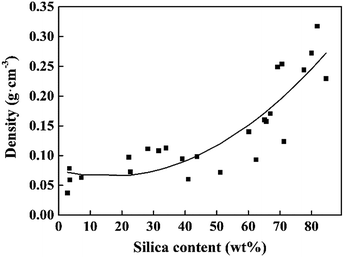
The microstructures of the CNF–silica aerogels were imaged using scanning electron microscopy (SEM) to observe the existence of silica particles on the cellulose nanofibril structure. The SEM images of the CNF, silica and CNF–silica aerogels with different silica contents (from low to high) are showed in Fig. 1. The CNF aerogel had a hierarchical network structure (Fig. 1a) and the silica aerogel had a “pearl necklace” structure consisting of assembled spherical silica individual particles (Fig. 1b). The cellulose-reinforced silica aerogel exhibited a fibrillary structure inherited from the cellulose network, and there seemed to be a superposition of the cellulose network and silica particles. With lower silica content (2.78 wt%, Fig. 1c) in the composite aerogel, the network structure was similar to that of the pure cellulose aerogel. With increasing silica content, more silica grains could be observed entrapped among the CNF fibrils. At the silica content of 28 wt% (Fig. 1d), the cellulose fiber skeleton was clearly revealed. It could be seen that a great assembly of cellulose “strands” was interconnected by individual nanofilaments, resulting from the increased silica agglomerations when the silica beads occupied almost half of the composite aerogel (Fig. 1e). Furthermore, when the silica content reached 80 wt% (Fig. 1f), only a few fiber skeletons could be seen. The silica particles abundantly coated the surface or were inlaid in the cellulose matrix, yielding a “robust” multiscale aerogel structure. It is obvious that the fiber skeleton was thickened by the growth of silica filling up the pores of the aerogel's network structure, which consequently caused the increasing density of aerogel system. The relationship between the aerogel density and the silica content (by mass) given in Fig. 2 confirms this result. This is the quadratic polynomial model established in JMP software. A well-fitting model could be described as follows:| Density = −0.022667 + 0.0027756 × silica content + 0.0000436 × (silica content − 47.434)2 |
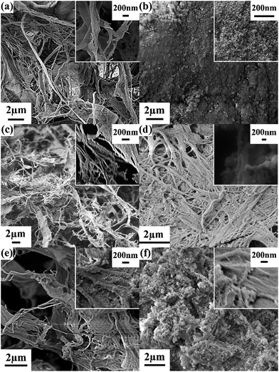 | ||
| Fig. 1 SEM images of (a) CNF, (b) silica, and CNF–silica aerogels with different silica content: (c) 2.78 wt%, run 23, (d) 28 wt%, run 4, (e) 46 wt%, run 13 (center) and (f) 80 wt%, run 3. | ||
The density can be seen as a function of the silica content as the two had a positive dependent relationship.
Compressive properties
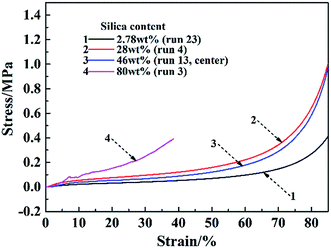
In this Box–Behnken experimental design, the compressive modulus of the samples ranged from 0.5 to 9.2 MPa, and the compressive strength ranged from 0.17 to 2 MPa. The compressive modulus and strength contour plots, according to the silica content of the CNF–silica aerogels, are represented in Fig. 3. A similar distribution of compressive modulus and strength was observed: when the silica content was around 30–50 wt%, the composite aerogels had higher compressive properties, while the aerogels with higher silica content displayed lower mechanical properties. Since the silica aerogels are composed of highly open structures in which the secondary particles of silica are connected to each other with only a few siloxane bonds, the structure of the native aerogels is too fragile to be handled.39 The compressive modulus and strength of pure silica aerogel have been reported in the literature at 0.18–0.47 MPa and 0.047–0.16 MPa, respectively.40,41 As expected, cellulosic scaffold loading with a certain amount of silica particles led to a nanoscale compatibilization effect, which is essential for the synthesis of composite materials with improved compressive properties. About 45% (13 in 29) of the samples yielded more than 50 wt% of silica in the composite aerogel system, resulting in weak mechanical properties. Representative plots of compressive stress vs. strain for the CNF–silica aerogels with different silica contents are given in Fig. 4. The deformation of the aerogels could be considered a linear elastic regime below 6% strain; it then gradually underwent more plastic deformation (non-linear). Finally, the compression process ended with stiffening. The composite aerogels with silica contents lower than 50 wt% showed high deformability, up to 85–90% strain, and failure of the materials with higher silica content was observed at 20–40% strain. The presence of CNF scaffolds within the silica aerogels with more highly open structures caused a deterioration of the mechanical properties. This behavior is believed to be directly related to poor interfacial adhesion between the cellulose fiber skeleton and the individual silica particles and weak connections between the silica particles. In the existence of more silica in the composite aerogel system, the CNF–silica interface is highly discontinuous and hence supports crack propagation, causing degradation of the mechanical properties instead of the desired reinforcement. The composite aerogels with 40–50 wt% silica content displayed a significant improvement of mechanical properties compared with the pure silica aerogels, but this was normally accompanied with a small increase in density (0.07–0.1 g cm−3).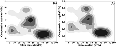 | ||
| Fig. 3 Contour plots of (a) compressive modulus vs. silica content and (b) compressive strength vs. silica content. | ||
The objective of this work was to find an optimum preparation process to obtain composite aerogels with a 40–50 wt% silica content, which would ameliorate the compressibility and stiffness of the silica aerogels.
Response surface methodology analysis
The influences of the operating variables on the silica content in the CNF–silica aerogel (model 1), the density (model 2), the compressive modulus (model 3), and the compressive strength (model 4) were investigated using response surface methodology (RSM). The ANOVA results of these models are outlined in Table 3. The statistical significance was checked by F values, P values, and the adequate precision ratio; the quality of the fit of the polynomial model was expressed by the coefficients of determination R2 and Radj2.42 Low P values corresponded to high statistical significance of the variables; P values less than 0.05 were accepted to be significant, whereas P values greater than 0.1 were not significant.42 The F values of 16.08 and 9.32 imply that the models are significant for silica content in CNF–silica aerogel and density. These two both have the P values < 0.0001, also indicating there is only a 0.01% chance that a “model F value” could occur due to noise. The F values of 1.18 and 1.40 imply that the compressive modulus and compressive strength model are not significant. This could confirm the result of the compressive properties distribution seen in the contour plots (Fig. 3): most samples retained more than 50 wt% silica, so that the compressive properties had lower values. The “adequate precision” indicates the signal-to-noise ratio; normally, a ratio greater than 4 is desirable for the model to be used effectively, which can be considered an adequate value for the model.43 Beside the models of compressive modulus and compressive strength, two other models had a ratio greater than 4, which could be used to navigate the design space. In addition, in the models of compressive modulus and strength, there were great differences between R2 and Radj2. In the experimental design, R2 is a measure of the amount of reduction in the variability of the response obtained by using the independent variables in the model. A large R2 value does not imply that the regression model is a good one, however; Radj2 is preferred for use in determining the fit of a regression model, as it does not always increase when variables are added.44 Therefore, except for compressive modulus and strength, the predicted data of the other two models (silica content and density) showed a good fit with the experimental results. These also could be confirmed in the plots of experimental versus calculated values of four responses (Fig. 5).| Source | SS | DF | MS | F value | P value |
|---|---|---|---|---|---|
| a R2 = 0.9414; Radj2 = 0.8829; adequate precision = 13.652.b R2 = 0.9031; Radj2 = 0.8062; adequate precision = 11.172.c R2 = 0.5420; Radj2 = 0.0840; adequate precision = 3.561.d R2 = 0.5834; Radj2 = 0.1668; adequate precision = 3.766. | |||||
| Model 1a | 16![[thin space (1/6-em)]](https://www.rsc.org/images/entities/char_2009.gif) 224.70 224.70 |
14 | 1158.91 | 16.08 | <0.0001 |
| Model 2b | 0.13 | 14 | 9.422 × 10⁻³ | 9.32 | <0.0001 |
| Model 3c | 160.51 | 14 | 11.46 | 1.18 | 0.3785 |
| Model 4d | 8.13 | 14 | 0.58 | 1.4 | 0.2685 |
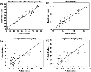 | ||
| Fig. 5 The experimental data versus predicted data for (a) model 1 silica content, (b) model 2 density, (c) model 3 compressive modulus, and (d) model 4 compressive strength. | ||
The response surface and corresponding contour plots were developed, providing an evaluation of the primary and interaction effects of experimental variables and their contribution in predicting the studied response. Fig. 6–9 present the influences of the CNF concentration, the TEOS concentration, the pH value of condensation and immersion time on the silica content, the density, the compressive modulus and the compressive strength. These plots present the function of two process parameters, keeping all other parameters at the fixed level.
Regarding the response of the silica content, based on the ANOVA results (Table S2†), it was evident that the CNF concentration, pH value, and immersion time were the significant single factors governing the yield of silica in the composite aerogels. In particular, the pH value had a great influence on the silica content (Fig. 6b, d and f): a higher pH value resulted in higher silica content. We reasoned that the higher pH value would accelerate the silica condensation speed and promote a greater yield of silica particles. We found that the CNF concentration had a negative impact on the silica content of the aerogels (Fig. 6a and c). The presence of less solid content in the CNF aerogels produced a more porous structure that had a larger capacity to load silica particles. There was an interaction effect between the TEOS concentration and the immersion time (Fig. 6e). At higher TEOS concentrations, which would result in a faster condensation, the silica particles agglomeration happened suddenly when they were just penetrating the CNF structure, preventing more silica from depositing deeply into the cellulosic structure. With increased immersion time, the cellulose scaffold was infused with more silica. But together with increasing TEOS concentration, the silica solution could not infiltrate and with continuous consumption during the gelation, the colloidal silica in the sol formed an overgrowth layer outside the CNF aerogel. After the drying process, the outer layer easily fell off, followed with a silica reduction in the composite aerogel. Similar to the ANOVA results on the silica content, the density was affected by the pH value (most significant), the CNF concentration and the immersion time (Table S3†). The contour surfaces of the density (Fig. 7) also displayed similar patterns to the contour plots of the silica content (Fig. 6), indicating similar effects of the interactions between the corresponding variables. In agreement with previous analyses, higher silica content corresponded to greater density of the composite aerogel.
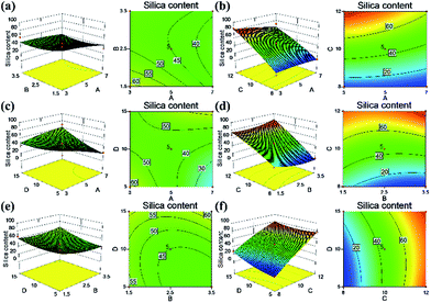 | ||
| Fig. 6 Response surface of independent variables on the silica content in the CNF–silica aerogels: (a) A–B, (b) A–C, (c) A–D, (d) B–C, (e) B–D and (f) C–D. | ||
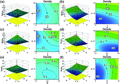 | ||
| Fig. 7 Response surface of independent variables on density in the CNF–silica aerogels: (a) A–B, (b) A–C, (c) A–D, (d) B–C, (e) B–D and (f) C–D. | ||
The contour response surfaces of the compressive modulus and the compressive stress are displayed in Fig. 8 and 9. Compared with the contour plots of silica content and density, the compressive properties plots were more elliptical, indicating interaction effects between the parameters studied. The aim of this study was to optimize the experimental conditions and formulations to ameliorate the fragile character of silica aerogels. As discussed previously, a designed composite aerogel would obtain high compressive properties with 40–50 wt% loading of silica particles. Herein, we defined the parameters: the CNF concentration ranged from 4% to 6% (CNF aerogel with low solid was too soft, while at a high solid content, the aerogel would produce bubbles inside the material or on the surface due to the poor homogeneity under the thick cellulose gel). The pH value ranged from 8 to 10 (high pH value yielding more silica particles), immersion time < 15 min (longer immersion forms an outer silica layer) and the target silica content was between 40 and 50 wt%. After the optimization using Design Expert software, the solutions suggested that the center sample would reach the target, which was to prepare CNF–silica aerogel using 5% CNF, TEOS concentration at 2.5 mol L−1, at 10 pH value, and immersing the CNF aerogel into silica sol for 10 min (Fig. S2†). This formulation was effective in producing the desired composite aerogel to improve the brittleness of the silica aerogel. This also confirmed the rationality of the selected range of parameters studied. In additional, the composite aerogel still had low density (0.1 g cm−3); furthermore, it also had low thermal conductivity (0.0226 W m−1 K−1) and water resistance (contact angle was 152.1°),32 allowing for the possibility of new and multi-functional application areas.
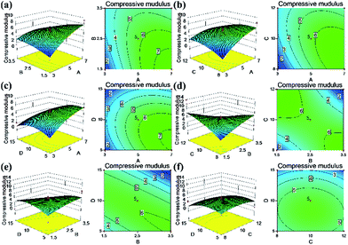 | ||
| Fig. 8 Response surface of independent variables on compressive modulus in the CNF–silica aerogels: (a) A–B, (b) A–C, (c) A–D, (d) B–C, (e) B–D and (f) C–D. | ||
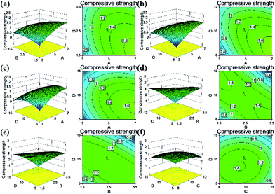 | ||
| Fig. 9 Response surface of independent variables on compressive strength in the CNF–silica aerogels: (a) A–B, (b) A–C, (c) A–D, (d) B–C, (e) B–D and (f) C–D. | ||
Conclusions
This work demonstrates a theoretical study on designing silica particles interpenetrated with a cellulose network structure. Cellulose nanofibril (CNF)-reinforced silica aerogels with improved mechanical properties were successfully achieved; in these aerogels, an interpenetrating silica “pearl-necklace” structure was formed inside the cellulose scaffold by immersing CNF aerogels into a silica sol in a two-step sol–gel process. The relationships among silica content, density, compressive modulus and compressive strength were investigated. The loading silica content in the CNF scaffold had a positive relationship with the density of the composite aerogel. The compressive properties greatly depended on the silica yield in the composite aerogel. The resulting composite aerogel with silica content between 40 and 50 wt% had high compressive properties, which concomitantly ameliorated the brittleness of the silica aerogels. To study the effects of the preparation parameters (CNF concentration, TEOS concentration, pH value of condensation process and immersion time) on the silica content, density and compressive properties of CNF–silica aerogels, a response surface methodology (RSM) was introduced to optimize the process to obtain the desired composite aerogel. In this case, the Box–Behnken design (BBD) was applied in the design. It was found that the independent variables had significant quadratic effect on the silica content and density of the composite aerogels. There were interaction effects among four factors on the compressive modulus and compressive strength. After optimization, the optimal preparation process was identified: immersing the solid content 5% CNF aerogel into the 2.5 mol L−1 TEOS solution for 10 min, adjusting the pH value of the condensation environment to 10. The compressive modulus and strength of the desired sample reached 6.57 MPa and 1.37 MPa, respectively. The compressive modulus was 13–36 times higher than that of pure silica aerogel (0.18–0.47 MPa), and the compressive strength was 8–30 times higher when compared with silica aerogel (0.047–0.16 MPa). In addition, the composite aerogel still had lighter weight, while the density was only 0.1 g cm−3; other qualities included low thermal conductivity (0.0226 W m−1 K−1) and water resistance (contact angle 152.1°, details in ESI†).32 The brittleness/fragility of the silica aerogels was greatly improved. Since silica aerogels have already been commercially applied in many fields, this cellulose-reinforced silica aerogel could widen opportunities for developing high quality, functional aerogels.Acknowledgements
This work was financially supported by the Special Fund for Forest Scientific Research in the Public Welfare (No. 201504603) and the 2014 UTIA Innovation Grant.Notes and references
- J. Fricke, J. Non-Cryst. Solids, 1988, 100, 169–173 CrossRef CAS.
- J. Fricke and A. Emmerling, J. Am. Ceram. Soc., 1992, 75, 2027–2036 CrossRef CAS.
- G. S. Kim, S. H. Hyun and H. H. Park, J. Am. Ceram. Soc., 2001, 84, 453–455 CrossRef CAS.
- C. E. Carraher, Polym. News, 2005, 30, 386–388 CrossRef CAS.
- Y. Chen, Z. Feng, X. Huang, X. Yu, W. Zheng and Z. Ren, Inorg. Chem. Ind., 2010, 42, 4–6 CAS.
- Q. Gao, C. Zhang, J. Feng, J. Feng, Y. Jiang and W. Wu, Journal of Materials Science & Engineering, 2009, 27, 302–306 CAS.
- S. White, S. Rouanet, J. Moses and J. O. Arnold, 4th International Symposium on Aerogels, Berkeley, CA, United States, 1994 Search PubMed.
- S. M. Jones, J. Sol-Gel Sci. Technol., 2006, 40, 351–357 CrossRef CAS.
- D. J. Shayler, A. Salmon and M. D. Shayler, Marswalk One: First Steps on a New Planet, Praxis Publishing, Chichester, UK, 2005 Search PubMed.
- R. D. Braun and R. M. Manning, J. Spacecr. Rockets, 2007, 44, 310–323 CrossRef.
- L. M. Popplewell, Y. Lei, R. L. Guerry, X. Huang, A. N. Kroenig and J. J. Mcelwee, US Pat., 20100143422, 2010.
- F. Barandeh, P. L. Nguyen, R. Kumar, G. J. Iacobucci, M. L. Kuznicki, A. Kosterman, E. J. Bergey, P. N. Prasad and S. Gunawardena, PLoS One, 2012, 7, e29424 CAS.
- G. Li, T. Zhu, Z. Deng, Y. Zhang, F. Jiao and H. Zheng, Chin. Sci. Bull., 2011, 56, 685–690 CrossRef CAS.
- L. Ye, Z. Ji, W. Han, J. Hu and T. Zhao, J. Am. Ceram. Soc., 2010, 93, 1156–1163 CrossRef CAS.
- S. Motahari and A. Abolghasemi, J. Mater. Civ. Eng., 2015, 27, 4015008 CrossRef.
- T. G. Glover, K. I. Dunne, R. J. Davis and M. D. LeVan, Microporous Mesoporous Mater., 2008, 111, 1–11 CrossRef CAS.
- X. Tong, T. Tang, Z. Feng and B. Huang, J. Appl. Polym. Sci., 2002, 86, 3532–3536 CrossRef CAS.
- Z. Zhang, J. Shen, X. Ni, G. Wu, B. Zhou, M. Yang, X. Gu, M. Qian and Y. Wu, J. Macromol. Sci., Part A: Pure Appl.Chem., 2006, 43, 1663–1670 CrossRef CAS.
- C. Kim, J. Lee and B. Kim, Colloids Surf., A, 2008, 313–314, 179–182 CrossRef.
- Z. Dong, X. Li and G. Yuan, Appl. Chem. Ind., 2006, 35, 440–442 CAS.
- H. Yang, W. Ni, T. Liang, G. Xu and L. Xu, J. Mater. Eng., 2007, 63–66 CAS.
- M. A. B. Meador, S. L. Vivod, L. McCorkle, D. Quade, R. M. Sullivan, L. J. Ghosn, N. Clark and L. A. Capadona, J. Mater. Chem., 2008, 18, 1843 RSC.
- H. Sai, L. Xing, J. Xiang, L. Cui, J. Jiao, C. Zhao, Z. Li, F. Li and T. Zhang, RSC Adv., 2014, 4, 30453 RSC.
- H. Sehaqui, M. Salajková, Q. Zhou and L. A. Berglund, Soft Matter, 2010, 6, 1824 RSC.
- Y. Habibi, L. A. Lucia and O. J. Rojas, Chem. Rev., 2010, 110, 3479–3500 CrossRef CAS PubMed.
- D. Tao, H. Bai, S. Liu and X. Liu, J. Cellul. Sci. Technol., 2011, 19, 64–75 CAS.
- I. Siró and D. Plackett, Cellulose, 2010, 17, 459–494 CrossRef.
- A. Demilecamps, G. Reichenauer, A. Rigacci and T. Budtova, Cellulose, 2014, 21, 2625–2636 CrossRef CAS.
- A. Demilecamps, C. Beauger, C. Hildenbrand, A. Rigacci and T. Budtova, Carbohydr. Polym., 2015, 122, 293–300 CrossRef CAS PubMed.
- S. Zhao, Z. Zhang, G. Sèbe, R. Wu, R. V. Rivera Virtudazo, P. Tingaut and M. M. Koebel, Adv. Funct. Mater., 2015, 25, 2326–2334 CrossRef CAS.
- R. P. Patel, N. S. Purohit, A. M. Suthar and S. K. Patel, Int. J. ChemTech Res., 2009, 1, 1052–1057 CAS.
- J. Fu, S. Wang, C. He, Z. Lu, J. Huang and Z. Chen, Carbohydr. Polym., 2016, 147, 89–96 CrossRef CAS PubMed.
- D. Liu, Q. Wu, R. L. Andersson, M. S. Hedenqvist, S. Farris and R. T. Olsson, J. Mater. Chem. A, 2015, 3, 15745–15754 CAS.
- S. Santhanam, J. Liang, R. Baid and N. Ravi, J. Biomed. Mater. Res., Part A, 2015, 103, 2300–2308 CrossRef CAS PubMed.
- M. Khajeh, J. Hazard. Mater., 2009, 172, 385–389 CrossRef CAS PubMed.
- Y. Meng, X. Wang, Z. Wu, S. Wang and T. M. Young, Eur. Polym. J., 2015, 73, 137–148 CrossRef CAS.
- Y. Meng, T. M. Young, P. Liu, C. I. Contescu, B. Huang and S. Wang, Cellulose, 2015, 22, 435–447 CrossRef CAS.
- W. Zhang, Y. Zhang, C. Lu and Y. Deng, J. Mater. Chem., 2012, 22, 11642 RSC.
- H. Maleki, L. Durães and A. Portugal, J. Non-Cryst. Solids, 2014, 385, 55–74 CrossRef CAS.
- A. Dourbash, S. Motahari and H. Omranpour, J. Non-Cryst. Solids, 2014, 405, 135–140 CrossRef CAS.
- H. Omranpour, A. Dourbash and S. Motahari, AIP Conf. Proc., 2014, 1593, 298–302 CrossRef CAS.
- B. K. Körbahti, J. Hazard. Mater., 2007, 145, 277–286 CrossRef PubMed.
- T. Ölmez, J. Hazard. Mater., 2009, 162, 1371–1378 CrossRef PubMed.
- J. E. Silveira, J. A. Zazo, G. Pliego, E. D. Bidóia and P. B. Moraes, Environ. Sci. Pollut. Res., 2015, 22, 5831–5841 CrossRef CAS PubMed.
Footnote |
| † Electronic supplementary information (ESI) available: The preparation process of CNF–silica aerogels, BBD design matrix, detail ANOVA results and test method of thermal conductivity and contact angle. See DOI: 10.1039/c6ra20986f |
| This journal is © The Royal Society of Chemistry 2016 |


