Electrospun hematite nanofiber/mesoporous silica core/shell nanomaterials as an efficient adsorbent for heavy metals

Shani Egodawattea, Katherine E. Greensteinb, Ivy Vancea, Edris Riveraa, Nosang V. Myungc, Gene F. Parkinb, David M. Cwiertnyb and Sarah C. Larsen*a
aDepartment of Chemistry, University of Iowa, USA. E-mail: sarah-larsen@uiowa.edu
bDepartment of Civil and Environmental Engineering, University of Iowa, USA
cUniversity of California-Riverside, Department of Chemical and Environmental Engineering, USA

Received 5th August 2016 , Accepted 14th September 2016

First published on 14th September 2016


Abstract

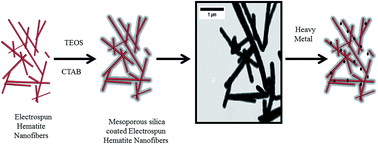
Functionalized nanomaterials hold tremendous promise for water treatment because their high surface area makes them ideal sorbents for pollutants like heavy metal ions that are pervasive in global water supplies. Here, a novel core/shell nanomaterial consisting of an electrospun hematite nanofiber core and a mesoporous silica shell of tunable thickness (from 20–60 nm) was prepared for the first time. The synthesis involved careful control of pH and sequential addition of the silica source to control the growth and ultimately, thickness of the mesoporous silica shell on the electrospun hematite nanofiber. The core/shell structure was subsequently tailored for heavy metal adsorption by grafting an aminopropyl functional group on the mesoporous silica surface. The resulting electrospun hematite/mesoporous silica core/shell nanomaterials were extensively characterized by energy dispersive spectroscopy (EDS) with high resolution transmission electron microscopy (HRTEM), and ζ potential measurements both before and after adsorption of the Cr(III), from aqueous solution. Notably, sorption capacities for Cr(III) exceeded those previously reported for other nanostructured sorbents for this metal. The advantages of these core/shell materials include controllable surface area through introduction of porosity and the option for facile surface modification to optimize physicochemical interactions for pollutant uptake. These nanocomposites also exhibit improved chemical resistance in harsh environments. At acidic pH values, for example, the core/shell nanomaterials were more chemically resistant to iron dissolution than the parent electrospun hematite nanofibers, which broadens the range of waste streams to which these sorbents can be applied.


1. Introduction

Hematite (α-Fe2O3) is the most thermodynamically stable form of iron oxide and, due to its low cost and natural abundance,1 it is widely used in applications including pigments, catalysis,2 gas sensing,3 magnetic devices, and electrode materials in lithium ion batteries.4–6 Given the variety of uses, synthesis of hematite with controllable morphologies and size is highly desirable. While hematite is readily synthesized in nanoparticle form,7 there are certain applications where the resulting nanoparticle dispersions are not preferred. For example, in water treatment, where hematite serves as a sorbent for metals,8 nanoparticle use has been limited by concerns over their inadvertent release into the treated water supply. One alternative may be electrospun hematite nanofibers, which hold the promise of being synthesized and deployed as a cohesive membrane or filter technology. This allows the high surface area to volume ratio of nanomaterials to be exploited in an immobilized treatment platform that limits risk of their release into the finished water supply. Furthermore, electrospinning is commercially viable and the raw material costs are low; thus we do not expect the cost of these materials to be prohibitive.9

Electrospinning is a low cost, simple and scalable method for generating ultra-long polymer and/or metal oxide fibers with tunable diameters in the range of a few microns to tens of nanometers.10–12 The unique mesh-like structure of the nanofibers results in a three-dimensional reticular structure with high specific surface area and porosity,13 ideal for water treatment applications. However, electrospun hematite nanofibers still have some limitations that may hinder their application in certain environments; they are unstable at acidic pH and can be brittle.14 To overcome these challenges, recent research studies have focused on the synthesis and application of electrospun nanofiber composites, in which reactive metal oxides such as ZnO and TiO2 are integrated with various supporting metal, polymer or carbon substrates.14,15

Mesoporous silica (MS) materials are mechanically, thermally and chemically stable matrices and have been used for the adsorption of environmental contaminants, catalysis, and sensing.16,17 Mesoporous silica nanomaterials have very high surface areas (around 1000 m2 g−1), good biocompatibility, tunable pore sizes and well-defined surface properties that can be tailored for specific applications by modifying the surface with functional groups.18–21 For example, mesoporous silica materials functionalized with groups such as amine, thiol, carboxy, sulfonate and phosphonates have shown enhanced adsorption for heavy metals including As, Hg, Pb and Co.16,22–24

In this work, the properties of electrospun hematite nanofibers (ESH) are combined with mesoporous silica to form a novel core/shell nanomaterial with a meso- and macroporous structure that has high adsorption capacity and is chemically stable. This core/shell nanomaterial composite was evaluated for the application of heavy metal adsorption from aqueous solution. Notably, heavy metal contaminated waste water is often acidic in nature, and a major limitation of iron oxide sorbents is that they exhibit limited stability in acidic media and thus cannot be used effectively to treat such waste streams.6,25 With enhanced stability in low pH aqueous matrices, these core/shell nanomaterials have the potential to exhibit higher adsorption capacity than the parent hematite nanofiber or the parent mesoporous silica owing to the coupling of the adsorption properties of these two materials.

Herein, we prepared electrospun hematite (ESH) nanofiber/mesoporous silica (MS) core/shell nanomaterials (ESH@MS) with a controlled silica shell thickness between 20–60 nm. This study represents the first time electrospun metal oxide nanofibers have been uniformly coated with a mesoporous silica shell of controlled thickness. The core/shell materials were functionalized with an aminopropyl group to enhance the heavy metal adsorptive properties and were extensively characterized by a variety of physicochemical techniques. The chemical stability of the core/shell material in highly acidic aqueous solution and the performance as a heavy metal adsorbent for Cr(III) was also evaluated. The nanomaterials were analyzed after adsorption to elucidate the speciation of the adsorbed heavy metal species in order to gain a molecular level understanding of the adsorption process of heavy metals on these materials.

2. Experimental details

2.1 Materials

3-Aminopropyltriethoxysilane (APTES, Sigma Aldrich), tetraethoxysilane (TEOS, Sigma Aldrich), hexadecyltrimethyl-ammonium bromide (CTAB, Sigma Aldrich), chromium(III) chloride (Sigma Aldrich), copper(II) nitrate (Sigma Aldrich), arsenic(III) oxide (Fisher Scientific), polyvinylpyrrolidone (PVP, MW 1[thin space (1/6-em)]300[thin space (1/6-em)]000, Sigma Aldrich), iron(III) nitrate nonahydrate (Sigma Aldrich), nitric acid (Fisher Scientific), sodium hydroxide (Fisher Scientific), ethanol (200 proof, Decon Laboratories), boric acid (99.8%, Alfa Aeser), and hydrofluoric acid (51% in water, Acros Organics) were utilized in this study.

2.2 Synthesis of electrospun hematite nanofibers (ESH)

For nanofiber synthesis, an iron precursor solution containing iron(III) nitrate nonahydrate (Fe(NO3)3·9H2O) and a polymer solution containing polyvinylpyrrolidone (PVP) were prepared. For the iron precursor solution, 9 g Fe(NO3)3·9H2O and 3 mL of deionized water were added in a 50 mL glass beaker and stirred at 500 rpm for 1 h. For the polymer solution, 0.47 g of PVP and 15.2 mL of ethanol were added in a 50 mL glass beaker and stirred using a magnetic stirrer at 500 rpm for 1 h. When the contents in both beakers were completely dissolved, they were mixed together and stirred for one hour at 60 °C, and then stirred overnight at room temperature.

For the electrospinning process, a 12 mL syringe was filled with the above mixture and loaded onto a syringe pump (New Era Pump Systems, Inc. NE-300). Using polyethylene tubing, the syringe was attached to a stand retrofitted with a metallic syringe adapter and 25-gauge plastic needle tip NanoNC (Korea). The stand was set 5 cm away from an Al foil-covered rotating drum, which served as the grounded collector. The metal adapter was connected to an Acopian (Easton, PA) high-voltage power supply set to 18 kV. The electrospinning chamber was heated to 35 °C. As the solution progressed through the system (0.4 mL h−1), it became electrified upon reaching the metal adaptor, resulting in electrospun nanofibers collected on the foil. After 14 h, the electrospinning process was ceased and the Al foil with the nanofibers was removed from the rotating drum. It was then inserted into a drying oven (Fisher Scientific Isotemp Oven 750G) at 60 °C overnight. Next, the nanofiber mat was placed in a tube furnace (MTI OTF-1200x-80) and annealed under air at 600 °C for 1 h for polymer removal and hematite crystallization.

2.3 Mesoporous silica coating of the electrospun hematite nanofibers (ESH@MS)

The hematite nanofibers were added to a mixture of cetyltrimethylammonium bromide (CTAB), sodium hydroxide (NaOH) and water in the molar ratios listed in Table S1. The mixture was sonicated to prepare a homogeneous dispersion and was heated at 70 °C under magnetic stirring. Next, tetraethylorthosilicate (TEOS) was added hourly in three equal amounts.26 The mixture was aged for 24 h to allow complete hydrolysis and polycondensation of the silicon source. The resulting components were centrifuged at 15[thin space (1/6-em)]120 g and the products were collected, washed with water and methanol and dried at 100 °C overnight. The dried product was calcined at 600 °C for 6 h in air to remove the CTAB. The iron content and the amount of TEOS added to the reaction mixture were varied to tune the thickness of the mesoporous silica coating around the electrospun hematite nanofibers. The coated electrospun nanofibers are labeled according to the thickness of the mesoporous silica shell. For example, ESH@MS-60 refers to electrospun hematite fibers (ESH) with a mesoporous silica (MS) coating of 60 nm.

2.4 Post-synthesis grafting of ESH@MS-60

The post-synthesis grafting procedure involved refluxing 100 mg of calcined ESH@MS-60 and APTES (0.4 mmol) in toluene at 120 °C for 6 h. The resulting samples were filtered, washed with 1[thin space (1/6-em)]:[thin space (1/6-em)]1 mixture of dichloromethane and diethylether and dried in an oven at 100 °C.27 These samples which are surface functionalized with the amine group will be referred to as ESH@MS-60-NH2. Loading of APTES was 1.34 mmol g−1 as measured by thermogravimetric analysis (TGA).

2.5 Adsorption experiments

Batch experiments were used to assess the performance of ESH, ESH@MS-60 and ESH@MS-60-NH2 as sorbents. In a typical experiment, 2.5 mg of the sample was mixed with 10 mL of the Cr(III) solution. The initial concentration of Cr(III) (from stock solutions prepared with CrCl3) were varied from 0.1 mM to 2.0 mM, and the pH of the solution was varied from 3–6 by adding HCl or NaOH. Additional adsorption experiments were conducted with Cu(II) and As(III) at pH 4.0 and pH 7.0 respectively. The samples were stirred for an appropriate time period and the contents were centrifuged at 15[thin space (1/6-em)]120 g in order to separate the solid from the supernatant. The Cr(III) samples were stirred for 2 h, Cu(II) samples were stirred for 48 h and the As(III) samples were stirred for 48 h. The supernatants were analyzed for the heavy metal content using inductively coupled plasma optical emission spectroscopy (ICP/OES). All the experiments were conducted in triplicate.

2.6 Iron dissolution experiments

Dissolution experiments were used to assess ESH, ESH@MS-20, ESH@MS-40 and ESH@MS-60. In a typical experiment, a concentration of 1 g L−1 was obtained by adding the sample to a pH = 1 solution made with diluted HCl and stirred for a specified period of time. The contents were centrifuged and filtered with 0.22 μm filters to ensure that there were no nanofibers in the supernatant. The supernatants were analyzed for iron content using ICP/OES.

2.7 Characterization

The physicochemical properties of the electrospun hematite nanofibers and the mesoporous silica coated electrospun hematite nanofibers were characterized using a variety of techniques. The identity of the type of iron oxide and the mesoporous structure of the silica coating was confirmed by powder X-ray diffraction (p-XRD) (Siemens D5000 and D8000 X-ray diffractometer with Cu Kα and a nickel filter). A broad-range pattern (2θ = 5 to 55 with a 0.02 step size, 1 s per step) and a small range spectrum (2θ = 1 to 5 with a 0.02 step size, 1 s per step) were collected.

The surface area and the pore size and diameter were measured using nitrogen adsorption/desorption isotherms with a Nova 1200 Nitrogen Adsorption Instrument (Quantachrome). The samples were degassed for 12 h at 120 °C and a 7-point BET method and a 50-point nitrogen adsorption desorption isotherm was measured and used to calculate the surface area and the pore volume and diameter, respectively. Inductively coupled plasma/optical emission spectroscopy (ICP/OES, Varian 720-ES) was used to determine the iron and silicon content of the samples. The samples were digested with hydrofluoric acid and diluted with the appropriate amount of nitric acid, boric acid and water.28 The results of nitrogen adsorption and ICP are listed in Table 1.

Table 1 Physicochemical characterization results
Sample Surface areaa (m2 g−1) Pore volumea (cm3 g−1) Pore diametera (nm) Fe/Si ratiob ζ potential (pH = 5.4) before Cr(III) adsorption ζ potential (pH = 5.4) after Cr(III) adsorption
a Measured by nitrogen adsorption isotherms.b Measured by ICP/OES.
ESH@MS-60 390 (±50) 0.2 (±0.02) 3.14 (±0.03) 0.54 (±0.03) −40 (±9) 22 (±5)
ESH@MS-40 215 (±3) 0.101 (±0.005) 3.12 (±0.01) 0.82 (±0.04)  
ESH@MS-20 110 (±20) 0.094 (±0.001) 3.14 (±0.03) 4.0 (±0.2)  
ESH 15 (±2) 1 (±7) 26 (±6)
ESH@MS-60-NH2 210 (±50) 0.13 (±0.01) 3.19 (±0.09) 0.66 (±0.03) 6 (±12) 22 (±7)


Transmission electron microscopy (TEM) imaging (JEOL JEM-1230 transmission electron microscope) was used to confirm the thickness of the mesoporous silica coating and the diameter of the hematite fiber core, as well as the morphology of the silica coating. To prepare samples for the TEM, a drop of dilute sample suspended in ethanol was placed on a copper/nickel grid with thin polymer coating and dried at room temperature prior to the measurement. 250 measurements were taken to measure the thickness of the mesoporous silica coating in different places along the length of the nanofibers with the mesoporous silica shell. Image J was used to measure the thickness of the mesoporous silica shell from the TEM images of the core shell material. The Energy Dispersive Spectroscopy (EDS) spectra were recorded with a JEOL JEM 2100F, installed with Thermo Scientifc NORAN system 7 for EDS imaging where the X-rays were collected from a NanoTrace SiLi detector. Scanning transmission electron microscopy (STEM) images were collected by a JEOL JEM 2100F. Scanning Electron Microspcopy (SEM) imaging (Hitachi S-4800) was used to image the fibers before and after coating. The fibers were added to methanol, were placed on a sample stud, dried and then sputter coated with gold nanoparticles prior to imaging.

Fourier transform infrared spectra (FTIR) were recorded using the Nicolet FT-IR (Nexus 670) spectrometer. The samples were pressed into disks by mixing them in the ratio of 1[thin space (1/6-em)]:[thin space (1/6-em)]180 with KBr. Thermogravimetric (TGA) analysis (TA instruments, Q 5000) with a heating rate of 5 °C min−1 was used to quantify the amount of amine groups grafted onto the ESH@MS-60-NH2 sample. 13C Magic Angle Spinning (MAS) NMR experiments were conducted on ESH@MS-NH2 samples at a spinning speed of 10 kHz with adamantane as the reference material.

ζ-Potential measurements were conducted on samples before (pH = 2 to 9) and after Cr(III)/Cu(II) adsorption at pH = 5.4 and pH = 4. A small amount of sample was placed in disposable plastic centrifuge tubes and 2 mL of the aqueous solution of desired pH was added. The resulting suspensions were sonicated for approximately 5 min (1510 Sonicator, Branson). The suspensions were then tested for ζ potential using Zetasizer Nano-ZS, Malvern Instruments.

3. Results and discussion

3.1 Synthesis and characterization of ESH@MS

A schematic representation of the synthesis of ESH@MS is illustrated in Fig. 1. In the first step, electrospun hematite nanofibers with a mean diameter of ∼100 nm were prepared. Next, a uniform layer of mesoporous silica was formed around the hematite nanofibers by controlling the amounts of surfactant (cetyltrimethylammonium bromide, CTAB), silica source (tetraethylorthosilicate, TEOS) and base (NaOH).26 In a given synthesis, the cationic surfactant, CTAB, orients along the negative surface of hematite, forming micelles around the nanofibers as shown in Fig. 1. The amount of CTAB that is added to the solution is the most crucial factor because this controls the formation of micelles around the nanofibers and prevents free silica formation.29 After the nanofiber-surfactant supramolecular structure has stabilized, the inorganic silica source, TEOS, was added in three equivalent batches in hourly increments.26 Since the solution conditions are very dilute, the TEOS hydrolyzes and polycondenses around the silicon source forming the micelles along the hematite nanofiber and minimizing the free silica formation. With each addition of TEOS, the formation of the silica adds to the previously formed silica, thickening the shell and increasing the uniformity and strength. To increase the thickness of the mesoporous silica shell, the amount of TEOS and CTAB was increased. Table S1 lists the reaction concentrations of the coated hematite nanofibers as molar concentrations of reactants.
image file: c6ra19876g-f1.tif
Fig. 1 Schematic representation of the synthesis of the electrospun hemtatite nanofiber/mesoporous silica nanocomposite (ESH@MS).

In addition to the CTAB and TEOS concentrations in the reaction solution, it was determined that pH played a very important role in the growth of the silica shell. The experimental pH of the reaction was varied from 9 to 12 by controlling the amount of added base. It was observed that pH = 10.80 was the optimum pH for the reaction, and the formation of free silica was minimal after sample cleanup. When the pH of the reaction was increased or decreased from pH = 10.80, the amount of free silica increased (Fig. S1). Representative samples with MS shell thicknesses of 20, 40 and 60 nm were prepared and are hereafter referred to as ESH@MS-20, ESH@MS-40, and ESH@MS-60. To improve the adsorptive properties, the core/shell materials were functionalized with APTES to form an aminopropyl functionalized surface.

SEM and TEM images were obtained and are shown in Fig. 2. These images provide the structural details of the ESH@MS samples including the thicknesses of the ESH cores and the mesoporous silica shells. The images indicate that the thickness of the mesoporous silica shell can be varied from approximately 20–60 nm by controlling the synthesis conditions. The histograms verify the thickness of the materials and is computed by counting 200 areas in an ESH@MS sample (Fig. S2). The length of the nanofiber and the ends of the nanofiber are uniformly coated with mesoporous silica and the core/shell structure is clearly observed by the difference in densities of silica and hematite in the TEM images in Fig. 2B–D. Higher magnification of the TEM images show that the silica shell is mesoporous (inset in Fig. 2C).


image file: c6ra19876g-f2.tif
Fig. 2 SEM and TEM images showing electrospun hematite nanofibers and ESH@MS core/shell materials. (A) SEM image of parent hematite nanofibers, and TEM images of (B) ESH@MS-60, (C) ESH@MS-40 (inset-a zoomed in version showing the mesoporosity of the shell), and (D) ESH@MS-20 where the number (ESH@MS-#) designates the approximate thickness of the shell in nanometers.

Fig. 3 shows the p-XRD patterns of the calcined samples, ESH, ESH@MS-20, 40 and 60. The low angle powder X-ray diffraction (p-XRD) pattern (Fig. 3A) shows a characteristic peak at 2θ ∼ 2, indicating short range order of the mesoporous shell, while the high angle p-XRD pattern (Fig. 3B) shows the characteristic peaks for the hematite core.26 The low intensity of the low angle peak is due to the incremental addition of the silicon source and indicates that the ordering of the mesopores is a more disordered or wormhole (WO) type of mesoporous silica. The amine functionalized electrospun hematite nanofiber/mesoporous silica core shell material (ESH@MS-60-NH2) has a low angle peak that is slightly shifted from the parent core shell material of similar thickness (ESH@MS-60). This is because the inclusion of the amine functional groups in the pores of the mesoporous silica makes the structure slightly more disordered. The diffraction patterns of the high angle p-XRD show the characteristic peaks of hematite which confirm its presence in the core/shell materials.30 In addition, when the thickness of the mesoporous silica shell increases, a broad peak around 2θ = 20 appears with growing intensity. This accounts for the high angle peak of amorphous silica formation and it is further evidence of the coating of mesoporous silica around the electrospun hematite nanofibers.


image file: c6ra19876g-f3.tif
Fig. 3 Powder X-ray diffraction patterns ((A) high angle p-XRD, (B) low angle p-XRD).

The porous nature of the mesoporous silica was confirmed by nitrogen adsorption–desorption isotherms for ESH@MS samples. The Brunauer–Emmett–Teller (BET) method was used to calculate the surface area and the Barrett–Joyner–Halenda (BJH) method was used to calculate the pore volume and diameter from the nitrogen adsorption isotherms. A representative nitrogen adsorption desorption isotherm for ESH@MS-40 is shown in Fig. S3. The adsorption isotherm is a type IV hysteresis curve which is typical of a mesoporous silica material.31 The surface area, pore volume and pore diameter for all the samples are given in Table 1. The ESH nanofibers have a relatively low surface area of 18 m2 g−1 which is increased significantly to 115, 215 and 394 m2 g−1 for ESH@MS-20, 40 and 60, respectively. After functionalization with APTES, the surface area and pore volume of ESH@MS-60-NH2 are reduced relative to ESH@MS-60 which can be attributed to the grafting of the aminopropyl groups in the mesopores.27,32

ζ-Potential measurements (Fig. 4) show that the parent ESH has a positive ζ-potential at low pH (pH = 3, +17 mV) that decreases as the pH increases (pH = 9, −28 mV) due to the deprotonation of the surface hydroxyl groups on the hematite surface with increasing pH. When the ESH nanofibers are coated with mesoporous silica (ESH@MS-60), the ζ potential is negatively charged in the entire pH range investigated (pH = 3, −36 mV and pH = 9, −40 mV) and this is attributed to the surface hydroxyl groups on the mesoporous silica surface. With amine functionalization, ESH@MS-60-NH2 trends towards a more positive ζ-potential in the whole range of pH values evaluated confirming that the amine group is covalently bound to the silica surface and is protonated until the pH approaches the pKa.


image file: c6ra19876g-f4.tif
Fig. 4 ζ potential measurements of ESH, ESH@MS-60 and ESH@MS-60-NH2 samples.

Thermogravimetric analysis (TGA), Fourier transform infrared (FTIR) spectroscopy, solid state 13C NMR and ζ-potential measurements confirmed the amine functionalization of the ESH@MS-60-NH2. Thermogravimetric analysis (TGA) indicated that the amine group loading in the ESH@MS-60-NH2 was 1.34 mmol g−1 (Fig. S4). Solid state 13C NMR and FTIR spectra shown in Fig. S5 and S6, respectively, also provide evidence of the aminopropyl group on the surface.

3.2 Chemical stability of ESH@MS core/shell materials

The ESH@MS nanomaterials were hypothesized to be more chemically stable at acidic pH compared to the parent ESH, which should enable their application to harsher waste streams. Dissolution experiments were conducted at room temperature using ESH, ESH@MS-20, ESH@MS-40, ESH@MS-60 in pH = 1 solution while monitoring total dissolved Fe concentration by ICP/OES. As shown in Fig. 5, the non-coated ESH exhibited a rapid, initial release of soluble Fe (3 mg L−1 by 4 h), and the soluble Fe concentration continued to increase over time. For mesoporous silica coated ESH, dissolution is inhibited relative to ESH, and the extent of dissolution decreases with increasing thickness of the silica shell. These results show that the mesoporous silica shell increases the chemical stability of ESH nanofibers in a highly acidic environment.
image file: c6ra19876g-f5.tif
Fig. 5 Dissolution of iron from ESH, ESH@MS-20, ESH@MS-40 and ESH@MS-60 samples.

3.3 Adsorption of heavy metals on ESH and ESH@MS materials

Batch adsorption experiments were conducted using Cr(III) as a model environmental contaminant in the pH range of 3–6. The pH of the solution is an important performance variable as this governs the aqueous speciation of the metal, as well as the surface charge of the core/shell material. Indeed, the adsorption capacity was found to depend on pH, and the optimum pH for Cr(III) adsorption was pH = 5.4. At higher pH values, Cr(III) precipitates as Cr(OH)3.33 To ensure that the removal of soluble form of Cr(III) was being assessed, adsorption isotherms for Cr(III) were conducted at this optimum pH value (pH = 5.4).

The adsorption isotherms for Cr(III) on ESH, ESH@MS-60 and ESH@MS-60-NH2 are shown in Fig. 6A. We note that our ability to conduct isotherm experiments with Cr(III) was limited to initial concentrations less than 2 mM, as higher concentrations at pH = 5.4 resulted in precipitation of Cr(III) solids. The adsorption isotherms of Cr(III) on ESH and ESH@MS-60 are very similar (Fig. 6A) indicating that the adsorption is not substantially affected by the MS shell alone. By comparison, the Cr(III) adsorption is enhanced on ESH@MS-60-NH2 (Fig. 6A) by amine functionalization of the mesoporous silica shell.


image file: c6ra19876g-f6.tif
Fig. 6 (A) Equilibrium adsorption isotherms for Cr(III) on core/shell nanocomposites and linearized adsorption isotherms with model fits assuming the (B) Freundlich and (C) Langmuir adsorption isotherm models. Data were obtained for Cr(III) at pH = 5.4 for ESH, ESH@MS-60 and ESH@MS-60-NH2 with model fit parameters reported in Table 2.

To analyze the adsorption data more quantitatively, the adsorption isotherms were fit to the Freundlich and Langmuir adsorption isotherm models (Fig. 6B and C). The Freundlich isotherm is given in eqn (1) below

 
qe = KFCe1/n (1)
where qe = equilibrium adsorption capacity, n = constant indicative of the intensity of the adsorption, Ce = equilibrium concentration of the metal ion, KF = Freundlich constant relative to the adsorption capacity. The Langmuir isotherm, which assumes monolayer uptake and thus exhibits a maximum adsorption capacity, is provided in eqn (2):
 
image file: c6ra19876g-t1.tif(2)
where: qm = Langmuir maximum adsorption capacity, Ce = equilibrium concentration of the solute in the bulk solution. The linearized form of the Langmuir equation, which can be used to determine model fit parameters from experimental data, is given below in eqn (3).
 
image file: c6ra19876g-t2.tif(3)

The adsorption data was fitted to both the Langmuir and Freundlich isotherm models. The resulting fits to the data are shown in Fig. 6B and C and the fitted parameters and associated errors are listed in Table 2.

Table 2 Fits for the Freundlich adsorption isotherm of Cr(III) adsorbed on ESH, ESH@MS-60 and ESH@MS-60-NH2 at pH = 5.4, respectively
  Freundlich isotherm (linear fit) Langmuir isotherm (linear fit)
R2 KF n R2 qm (mmol g−1) KL (L mmol−1)
ESH 0.94 2.46 (±0.1) 1.2 (±0.1) 0.86 4.0 (±0.6) 708 (±0.05)
ESH@MS-60 0.97 2.42 (±0.06) 1.35 (±0.09) 0.91 3.4 (±0.4) 4790 (±10)
ESH@MS-60-NH2 0.99 4.00 (±0.06) 1.10 (±0.03) 0.95 6.6 (±0.6) 478.6 (±0.7)


For Cr(III) uptake, the Freundlich isotherm model exhibited overall the best fit (based on R2 analysis) to our experimental adsorption data (Fig. 6B and Table 2). The aminopropyl functionalization on the mesoporous silica coated nanofiber (ESH@MS-NH2) resulted in the greatest Cr(III) uptake relative to the other core/shell materials based on fitted values of KF and qm. Model fit KF values were comparable for ESH and ESH@MS-60, but increased markedly after aminopropyl functionalization, consistent with a higher affinity of Cr(III) for the surface sites on the aminopropyl functionalized nanocomposite. For comparison the adsorption isotherms were also fit to the Langmuir model and the results are provided in Fig. 6C and Table 2 but the R2 values were lower relative to the Freundlich fits.

The Freundlich isotherm accounts for a mechanism of multisite adsorption, while the Langmuir isotherm assumes a single binding site with a capacity limited to a monolayer. The core–shell nanocomposites, and especially the aminopropyl functionalized core–shell nanocomposite, have several different adsorption sites available for Cr(III) uptake. These include the surface hydroxyl groups of the iron oxide core, the surface silanol groups in the mesoporous silica shell, and the amine groups in the nanocomposite. Therefore, the Freundlich isotherm seems better suited to describe and model the adsorption phenomena occurring on such heterogeneous sorbent surfaces.

To quantify the maximum adsorption capacities for these materials, the linearized form of the Langmuir isotherm and the fitted qm values are most convenient. Langmuir estimates of adsorption capacities for ESH, ESH@MS-60 and ESH@MS-60-NH2 were 4, 3.4, 6.6 mmol Cr(III) per g sorbent, respectively. Out of the materials explored, the surface modification of the nanocomposite by the aminopropyl group exhibited the highest capacity, a value that compares well to adsorption capacities reported for similar adsorbents of Cr(III), which are provided in Table 3 for comparison. The adsorption capacities of other heavy metals such as Cu(II) and As(III) were also compared with Cr(III). For Cu(II), the adsorption capacities of ESH, ESH@MS-60 and ESH@MS-NH2 were 0.34 (±0.04), 1.3 (±0.4), 2.2 (±0.5) mmol g−1, respectively. For As(III) the adsorption capacities are 0.42 (±0.4) and 0.25 (±0.05) mmol g−1 for ESH and ESH@MS-60, respectively.

Table 3 Comparison of equilibrium adsorption capacities of various adsorbents as reported in the literature
Adsorbent material Heavy metal Capacity (mmol g−1) Experimental conditions (pH, temperature, contact time) Reference
a Determined from adsorption data fitted to Langmuir isotherm (linearized form).b Fe3O4–SiO2-poly(1,2-diaminobenzene) sub-micron particles.
ESH Cr3+ 4.00 pH = 5.4, 298 K, 2 h This studya
ESH@MS-60 Cr3+ 3.4 pH = 5.4, 298 K, 2 h This studya
ESH@MS-60-NH2 Cr3+ 6.6 pH = 5.4, 298 K, 2 h This studya
Amino functionalized electrospun mesoporous silica Cr3+ 1.81 pH = 7.5, 298 K, 40 min 34
Fe3O4 Cr3+ 0.31 pH = 3.0; 298 K, 1 h 35
FSPb sub micron particles Cr3+ 1.48 pH = 5.3, 303 K, 2 h 36
m-MCM-41 Cr3+ 0.70 pH = 5.4, 298 K, 2 h 32
m-MCM-41-NH2 Cr3+ 2.08 pH = 5.4, 298 K, 2 h 32


To better understand the molecular basis for the adsorption of Cr(III) and Cu(II) on the EHS@MS nanomaterials, TEM/EDS mapping and ζ-potential measurements were conducted on the samples after heavy metal adsorption. The EDX mapping (Fig. 7 and S7–S9) show the spatial distribution of Fe, Si, O, and N on the amine functionalized samples. The intense and the relatively thinner maps of Fe in ESH, ESH@MS and ESH@MS-NH2 show the presence of the hematite core, and the strong signals of Si and O throughout the particles in the ESH@MS and ESH@MS-NH2 samples illustrate that the particles have a uniform coating of mesoporous silica. In the functionalized samples, the presence of N can be seen over the whole fiber, which confirms that the functionalization has taken place throughout the mesoporous silica framework. Nitrogen has a lower intensity compared to Si or O as the core/shell functionalized material is only 1.34 mmol per gram of nitrogen. In Fig. 7, the distribution of the adsorbed heavy metal, Cr(III) on ESH@MS can be clearly seen in the elemental maps. The Cr(III) and Cu(II) is distributed over the entire core/shell nanofiber rather than being locally adsorbed on just the iron oxide core.


image file: c6ra19876g-f7.tif
Fig. 7 STEM bright field images and EDS spectra of Cr(III) adsorbed on ESH@MS-60 at pH = 5.4.

The surface charge of the materials is also important in understanding the adsorption of these metal ions. ζ potential measurements were conducted on ESH, ESH@MS, ESH@MS-NH2 after Cr(III) and Cu(II) adsorption at pH = 5.4 and pH 4 respectively (Table 1). It can be seen that after the adsorption of Cr(III) and Cu(II), the ζ potential of the material shifted towards a more positive value in all cases. For Cr(III), the ζ potential values shifted from +1, −40 and 6 mV to +26, +22, +22 mV and for Cu(II) the potential values shifted from +7, −35 and 30 mV to +16, −12, +40 mV for ESH, ESH@MS-60, ESH@MS-NH2, respectively. This suggests that there is a positive complex being adsorbed on the surface. At pH = 5.4 the dominant species in aqueous solution are Cr(OH)2+ and Cr(OH)2+, and at pH 4, the dominant species in aqueous solution is Cu(OH)+. In the amine modified materials, the heavy metals can coordinate to the amine group forming a dative bond, whereas in the ESH and the ESH@MS, the adsorption of heavy metals is due to the deprotonated hydroxyl groups on the surface.32 Whereas the adsorption capacity is higher for cations, it is relatively low for anions, and thus it can be inferred that these materials are more efficient sorbents for cations. This may be due to mesoporous silica being negatively charged above pH 2, and this negative charge will repel anions and limit their interaction with the surface. For cation uptake on ESH@MS-NH2, particularly Cr(III), the uptake is believed to involve coordination between the cation and the amine nitrogen.32

4. Conclusion

A facile synthesis procedure was designed and optimized to prepare ESH@MS, a core/shell material with an electrospun hematite nanofiber core and a mesoporous silica shell of a controlled thickness in the 20–60 nm range. These core/shell materials possess high surface areas and surface properties that can be controlled by modifying the mesoporous silica surface with various functional groups. The core/shell materials exhibited improved chemical resistance relative to the core material alone at acidic pH as demonstrated by iron dissolution experiments. The application of these nanofiber iron oxide mesoporous silica core/shell materials in heavy metal adsorption was investigated using Cr(III) as a representative heavy metal contaminant. The core/shell materials had high adsorption capacities for Cr(III), with the amine modified core–shell material exhibiting the highest overall adsorption capacity. ζ-Potential measurements and TEM/EDS experiments suggested that the adsorbed heavy metal complexes are positively charged and are uniformly distributed over the core/shell materials. These core/shell nanomaterials have potential to be applied as heavy metal adsorbents with improved chemical resistance and high adsorption capacity.

Acknowledgements

This work was supported by the Center for Health Effects for Environmental Contamination at the University of Iowa and through the US EPA Science to Achieve Results (STAR) grant (#R835177). KEG was supported by a University of Iowa Presidential Graduate Research Fellowship through the University of Iowa Graduate College and ER was supported by NSF CHE-1062575.

References

  1. S. Cavaliere-Jaricot, A. Brioude and P. Miele, Langmuir, 2009, 25, 2551–2553 CrossRef CAS PubMed.
  2. P. Zhang, T. Chen, X. Zou, C. Zhu, D. Chen and H. Liu, Chin. J. Catal., 2014, 35, 99–107 CrossRef CAS.
  3. N. D. Cuong, T. T. Hoa, D. Q. Khieu, N. D. Hoa and N. Van Hieu, Curr. Appl. Phys., 2012, 12, 1355–1360 CrossRef.
  4. C. T. Cherian, J. Sundaramurthy, M. Kalaivani, P. Ragupathy, P. S. Kumar, V. Thavasi, M. V. Reddy, C. H. Sow, S. G. Mhaisalkar, S. Ramakrishna and B. V. R. Chowdari, J. Mater. Chem., 2012, 22, 12198–12204 RSC.
  5. L. Ji, O. Toprakci, M. Alcoutlabi, Y. Yao, Y. Li, S. Zhang, B. Guo, Z. Lin and X. Zhang, ACS Appl. Mater. Interfaces, 2012, 4, 2672–2679 CAS.
  6. J. Zhang, A. Thurber, C. Hanna and A. Punnoose, Langmuir, 2009, 26, 5273–5278 CrossRef PubMed.
  7. M. Zhu, Y. Wang, D. Meng, X. Qin and G. Diao, J. Phys. Chem. C, 2012, 116, 16276–16285 CAS.
  8. C.-Y. Cao, J. Qu, W.-S. Yan, J.-F. Zhu, Z.-Y. Wu and W.-G. Song, Langmuir, 2012, 28, 4573–4579 CrossRef CAS PubMed.
  9. L. Persano, A. Camposeo, C. Tekmen and D. Pisignano, Macromol. Mater. Eng., 2013, 298, 504–520 CrossRef CAS.
  10. W. E. Teo and S. Ramakrishna, Nanotechnology, 2006, 17, R89 CrossRef CAS PubMed.
  11. V. Thavasi, G. Singh and S. Ramakrishna, Energy Environ. Sci., 2008, 1, 205–221 CAS.
  12. T. Pirzada, S. A. Arvidson, C. D. Saquing, S. S. Shah and S. A. Khan, Langmuir, 2014, 30, 15504–15513 CrossRef CAS PubMed.
  13. Z. Ma, H. Ji, Y. Teng, G. Dong, J. Zhou, D. Tan and J. Qiu, J. Colloid Interface Sci., 2011, 358, 547–553 CrossRef CAS PubMed.
  14. M. Xi, X. Wang, Y. Zhao, Q. Feng, F. Zheng, Z. Zhu and H. Fong, Mater. Lett., 2014, 120, 219–223 CrossRef CAS.
  15. M. Xi, X. Wang, Y. Zhao, Z. Zhu and H. Fong, Appl. Phys. Lett., 2014, 104, 133102 CrossRef.
  16. A. Walcarius and L. Mercier, J. Mater. Chem., 2010, 20, 4478–4511 RSC.
  17. H. Zhu, B. Lee, S. Dai and S. H. Overbury, Langmuir, 2003, 19, 3974–3980 CrossRef CAS.
  18. B. G. Trewyn, S. Giri, I. I. Slowing and V. S. Y. Lin, Chem. Commun., 2007, 3236–3245,  10.1039/b701744h.
  19. S. Nayab, A. Farrukh, Z. Oluz, E. Tuncel, S. R. Tariq, H. u. Rahman, K. Kirchhoff, H. Duran and B. Yameen, ACS Appl. Mater. Interfaces, 2014, 6, 4408–4417 CAS.
  20. X. Li, J. Zhang and H. Gu, Langmuir, 2011, 27, 6099–6106 CrossRef CAS PubMed.
  21. Y. Ma, L. Xing, H. Zheng and S. Che, Langmuir, 2010, 27, 517–520 CrossRef PubMed.
  22. S. Budi Hartono, S. Qiao, K. Jack, B. P. Ladewig, Z. Hao and G. Lu, Langmuir, 2009, 25, 6413–6424 CrossRef PubMed.
  23. M. Vinoba, K. S. Lim, S. H. Lee, S. K. Jeong and M. Alagar, Langmuir, 2011, 27, 6227–6234 CrossRef CAS PubMed.
  24. R. I. Nooney, M. Kalyanaraman, G. Kennedy and E. J. Maginn, Langmuir, 2001, 17, 528–533 CrossRef CAS.
  25. C. A. Lanzl, J. Baltrusaitis and D. M. Cwiertny, Langmuir, 2012, 28, 15797–15808 CrossRef CAS PubMed.
  26. X. Lu, H. Liu, C. Deng and X. Yan, Chem. Commun., 2011, 47, 1210–1212 RSC.
  27. A. Datt, I. El-Maazawi and S. C. Larsen, J. Phys. Chem. C, 2012, 116, 18358–18366 CAS.
  28. A. Petushkov, S. Yoon and S. C. Larsen, Microporous Mesoporous Mater., 2011, 137, 92–100 CrossRef CAS.
  29. Y. Su, S. Qiao, H. Yang, C. Yang, Y. Jin, F. Stahr, J. Sheng, L. Cheng, C. Ling and G. Q. Lu, Nanotechnology, 2010, 21, 065604 CrossRef PubMed.
  30. X. Ye, D. Lin, Z. Jiao and L. Zhang, J. Phys. D: Appl. Phys., 1998, 1998, 2739–2744 CrossRef.
  31. S. Huh, H.-T. Chen, J. W. Wiench, M. Pruski and V. S. Y. Lin, Angew. Chem., Int. Ed., 2005, 44, 1826–1830 CrossRef CAS PubMed.
  32. S. Egodawatte, A. Datt, E. A. Burns and S. C. Larsen, Langmuir, 2015, 31, 7553–7562 CrossRef CAS PubMed.
  33. B. Bagheri, M. Abdouss, M. M. Aslzadeh and A. M. Shoushtari, Iran. Polym. J., 2010, 19, 911–925 CAS.
  34. A. A. Taha, J. Qiao, F. Li and B. Zhang, J. Environ. Sci., 2012, 24, 610–616 CrossRef CAS.
  35. S. Luther, N. Brogfeld, J. Kim and J. G. Parsons, J. Colloid Interface Sci., 2013, 400, 97–103 CrossRef CAS PubMed.
  36. F. Zhang, J. Lan, Z. S. Zhao, Y. Yang, R. Q. Tan and W. J. Song, J. Colloid Interface Sci., 2012, 387, 205–212 CrossRef CAS PubMed.

Footnote

Electronic supplementary information (ESI) available. See DOI: 10.1039/c6ra19876g

This journal is © The Royal Society of Chemistry 2016
Click here to see how this site uses Cookies. View our privacy policy here.