A highly active molybdenum multisulfide electrocatalyst for the hydrogen evolution reaction†
Li-Fang Zhang‡
ab,
Gang Ou‡b,
Liu Guc,
Zhi-Jian Pengc,
Lu-Ning Wang*ad and
Hui Wu*b
aSchool of Materials Science and Engineering, University of Science and Technology Beijing, Beijing 100083, P. R. China. E-mail: luning.wang@ustb.edu.cn
bState Key Laboratory of New Ceramics and Fine Processing, School of Materials Science and Engineering, Tsinghua University, Beijing 100084, P. R. China. E-mail: huiwu@tsinghua.edu.cn
cSchool of Engineering and Technology, China University of Geosciences, Beijing 100083, P. R. China
dState Key Laboratory for Advanced Metals and Materials, University of Science and Technology Beijing, Beijing 100083, P. R. China
First published on 28th October 2016
Abstract
We prepared a highly active molybdenum multisulfide (MoSx) hybrid material by an arc-melting method, which exhibits superior activity in acid media with a low overpotential of 156 mV at j = 10 mA cm−2, and a Tafel slope of 58 mV dec−1, surpassing most existing molybdenum-sulfide-based catalysts.
The hydrogen evolution reaction (HER) from electrocatalytic water splitting offers a promising strategy to produce H2.1 However, the most efficient HER catalysts so far, platinum (Pt) and Pt-based material, are expensive and scarce, which impede their scale-up deployment.2 To develop a scalable, environmentally friendly production of an inexpensive, highly active, stable HER catalyst remains a challenge.3 To replace the noble metal catalysts, cost-effective and active HER catalysts have been explored, including Ni and Ni-based alloys, transition metal sulfides, nitrides, phosphides, carbides, and selenides, as well as non-metal composites.2d,4 Particularly, MoS2 materials have been intensely studied for HER applications owing to its low cost, earth abundance, high catalytic activity and good stability.5 Many effort, such as maximally exposing edge sites using nanostructured MoS2, introducing defects, and chemical doping, has been made to improve the performance of MoS2 as HER catalysts.6 Dai et al. developed a solvothermal method to fabricate a MoS2/graphene hybrid material, showing a remarkable HER.7 Zheng et al. reported that the monolayer 2H-MoS2 by introducing sulphur (S) vacancies and straining yielded the optimal hydrogen adsorption free energy (ΔGH) equivalent to 0 eV, leading to higher HER activity.8 New active phase of molybdenum multisulfide (MoSx) has also been investigated as HER electrodes. However, they still exhibited poor performance compared with MoS2 materials.9 Hu et al. reported that electrochemically-deposited MoSx materials were efficient HER catalysts for the first time, showing significant geometric current densities (η = 242 mV at j = 10 mA cm−2).10 Markovic et al. combined the higher activity of CoSx building blocks with the higher stability of MoSx units into a compact and robust CoMoSx chalcogel structure, to design a low-cost alternative for HER in both alkaline and acidic environments.11 Moreover, previous reported procedures for synthesizing these catalysts usually involved low efficient fabrication process, like ultrahigh-vacuum processing, high-temperature treatment, sulfidization using H2S gas, and electrodeposition, severely limiting the scale-up production of molybdenum-sulfide-based catalysts.12
Recently, we have developed a simple and efficient arc-melting technique for scale-up defective solid oxides production.13 The typical arc-melting process involves two steps: (1) the materials can be immediately heated beyond their melting point; (2) the molten can be subsequently cooled down to room temperature in a few seconds.14 We propose that such extremely high cooling process may also provide possibility to implant defects in molybdenum sulfides. Herein, we use the efficient and straightforward arc-melting method to fabricate a new molybdenum multisulfide (Mo2S3 and Mo3S4) hybrid material, introducing abundant active sites via the formation of defects within this material, leading to a significant improvement of the hydrogen evolution activity.
The A-MoSx catalysts were prepared by the one-step arc-melting method. Firstly, the original MoS2 powders were pressed into pellets and then were arc-melting treated in the closed arc furnace filled with Ar. During the treatment, the MoS2 pellets were rapidly heated up to a high temperature over 3000 °C and melted, then cooled to room temperature within a few seconds on a copper substrate (maintained at 15 °C). The as-prepared black particles were ground to powders, followed by ball-milling.
SEM image in Fig. 1a portrays that the morphology of A-MoSx differs greatly from the original MoS2, transforming into particles from layer structure (Fig. S1†). The majority of the particles are in the range of 50–500 nm, quite consistent with particle size analysis result (Fig. 1b). The average particle size of A-MoSx is 224 nm, a little bigger than that of MoS2 (Fig. S2†). Fig. 1c shows the X-ray diffraction (XRD) pattern of the as-synthesized A-MoSx, indicating that the sample is composed of a mixture of several molybdenum multisulfide, in which Mo2S3 and Mo3S4 are dominate components. Notably, the intensity of the diffraction peaks from the MoS2 obviously weakened after arc-melting treatment, indicating an almost complete conversion from MoS2 to other molybdenum multisulfide. Transmission electron microscopy (TEM) was also applied to examine its morphology. The high-resolution TEM (HR-TEM) graph (Fig. 1d and f) exhibits a well-arrayed (101) plane of Mo3S4 with plane distance of 0.644 nm and (112) plane of Mo2S3 with a plane distance of 0.244 nm, quite consistent with XRD.
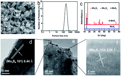 | ||
| Fig. 1 (a) SEM image of the A-MoSx. (b) Size analysis of the A-MoSx. (c) XRD pattern of the A-MoSx and MoS2. (e) TEM image of the A-MoSx. (d and f) HRTEM image of the A-MoSx. | ||
Raman and photoluminescence (PL) spectra further illustrate the structure changes from MoS2 to A-MoSx. As shown in Fig. 2a, the broadening of both A1g and E12g peaks in Raman spectra compared to MoS2 are observed. Furthermore, after arc-melting, the peak position of A-MoSx shifts from 407.91 cm−1 to 405.02 cm−1 for A1g mode, and from 383.44 cm−1 to 378.76 cm−1 for E12g mode. These results confirm the lattice distortion.15 Fig. 2b shows a PL image of A-MoSx and MoS2. The PL intensity of A-MoSx obviously decreases, suggesting that defects and cracks were formed after arc-melting.15,16 Fig. 2c and d shows the XPS profiles of Mo-3d and S-2p acquired from the MoS2 and A-MoSx, respectively. Compared to MoS2, XPS spectrum of A-MoSx shows variations in the observed more Mo valence states and core-level spectra with low binding energy feature peak (161.5 eV) being detected for S 2p core-levels. Fitting of the A-MoSx Mo-3d data reveals four species: Mo2+ (229 eV), Mo3+ (230 eV), Mo6+ (232 eV), Mo4+ (236 eV).17 The peak of Mo2+, Mo3+ and Mo4+ are assigned to Mo2S3, Mo3S4, and residue MoS2. And the peak of Mo6+ is attributed to Mo species that have been oxidized upon air exposure. Additionally, according to the analysis of S 2p XPS spectrum, the A-MoSx with low binding energy feature peak (161.5 eV) would appear highly defective, consistent with the Raman and PL results.18
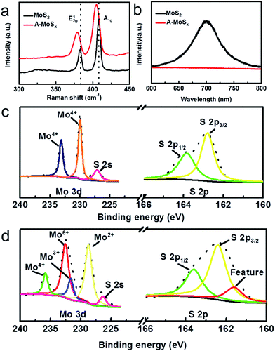 | ||
| Fig. 2 (a) Raman spectra of A-MoSx and MoS2. (b) Photoluminescence spectra of the A-MoSx and MoS2. XPS spectra of (c) MoS2; (d) A-MoSx. | ||
The catalytic performance for the HER of the catalysts was tested in 0.5 M sulfuric acid electrolyte using a three-electrode setup in a static state without rotation to mimic real industrial operation. Three candidates, including A-MoSx, MoS2, and commercial Pt/C, were examined. As shown in Fig. 3a, the prepared A-MoSx displays a much lower overpotential, 156 mV at the current density of 10 mA cm−2, which is more positive than original MoS2 (330 mV at j = 10 mA cm−2) and even many previously reported molybdenum-sulfide-based catalysts (Table S1†), suggesting a prominent HER activity. On the other hand, the cathodic current density at η = 300 mV of the A-MoSx catalysts is 42 mA cm−2, which is about 5 times greater than that of the MoS2 catalysts (7 mA cm−2). The Tafel plots (Fig. 3b) are used to determine Tafel slopes and exchange current densities by fitting to the Tafel equation η = b![[thin space (1/6-em)]](https://www.rsc.org/images/entities/char_2009.gif) log(j) + log(j0) (η is the overpotential, j is the current density, j0 is the exchange current density, and b is the Tafel slope). The A-MoSx catalysts resulted in a Tafel slope of 58 mV dec−1 compared to Tafel slop of 39 and 90 mV dec−1 for the Pt/C and the original MoS2, respectively. The Tafel slope falls within the range of 40–120 mV dec−1, indicating that the HER taking place on the A-MoSx surface would proceed through a Volmer–Heyrovsky mechanism, and the desorption of hydrogen is the rate limiting step.20 The HER exchange current density (j0) for the A-MoSx, calculated from the Tafel plots by extrapolation method, is 0.40 mA cm−2, which outperforms that of the MoS2 (0.19 mA cm−2), indicating a better catalytic activity. Fig. 3c portrays that I–V curves of the A-MoSx are almost the same at scan rates from 5 to 300 mV s−1, demonstrating its excellent stability. Electrochemical impedance spectroscopy (EIS) analyses are further performed to explore the HER kinetics at the electrode/electrolyte interface. The EIS data of the MoS2 and A-MoSx catalysts are illustrated by the Nyquist plots shown in Fig. 3d. The equivalent circuit we used in EIS analysis has been given in Fig. S6.† To decouple the ohmic resistance from the polarization resistance, we applied a model of ohmic resistance (Rs) in series with a module, where the polarization resistance (Rct) is in parallel with a constant phase element (CPE).21 It is clearly seen that the radius of semicircle in the low frequency zone of the A-MoSx catalysts is much smaller compared with that of the MoS2, suggesting the better conductivity.
log(j) + log(j0) (η is the overpotential, j is the current density, j0 is the exchange current density, and b is the Tafel slope). The A-MoSx catalysts resulted in a Tafel slope of 58 mV dec−1 compared to Tafel slop of 39 and 90 mV dec−1 for the Pt/C and the original MoS2, respectively. The Tafel slope falls within the range of 40–120 mV dec−1, indicating that the HER taking place on the A-MoSx surface would proceed through a Volmer–Heyrovsky mechanism, and the desorption of hydrogen is the rate limiting step.20 The HER exchange current density (j0) for the A-MoSx, calculated from the Tafel plots by extrapolation method, is 0.40 mA cm−2, which outperforms that of the MoS2 (0.19 mA cm−2), indicating a better catalytic activity. Fig. 3c portrays that I–V curves of the A-MoSx are almost the same at scan rates from 5 to 300 mV s−1, demonstrating its excellent stability. Electrochemical impedance spectroscopy (EIS) analyses are further performed to explore the HER kinetics at the electrode/electrolyte interface. The EIS data of the MoS2 and A-MoSx catalysts are illustrated by the Nyquist plots shown in Fig. 3d. The equivalent circuit we used in EIS analysis has been given in Fig. S6.† To decouple the ohmic resistance from the polarization resistance, we applied a model of ohmic resistance (Rs) in series with a module, where the polarization resistance (Rct) is in parallel with a constant phase element (CPE).21 It is clearly seen that the radius of semicircle in the low frequency zone of the A-MoSx catalysts is much smaller compared with that of the MoS2, suggesting the better conductivity.
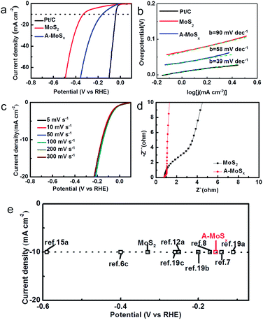 | ||
| Fig. 3 (a) The HER polarization curves of various catalysts (Pt/C, MoS2 and A-MoSx) with a scan rate of 50 mV s−1 in 0.5 M H2SO4. (b) The corresponding Tafel plots of various catalysts (Pt/C, MoS2 and A-MoSx). Each green dashed line is the fitting slope of the corresponding Tafel plot. (c) The polarization curves of the A-MoSx with different scan rate from 5 to 300 mV s−1 in 0.5 M H2SO4. (d) Electrochemical impedance spectra of the A-MoSx and MoS2 in 0.5 M H2SO4. (e) The HER current density at 10 mA cm−2 versus overpotential for various catalysts in acid media.6c,7,8,12a,15a,19 | ||
Over the last decade, molybdenum-sulfide-based materials have gained growing attention for use as HER electrocatalysts.22 We list a number of latest literature reports molybdenum-sulfide-based materials and compare their HER performance. As summarized in Fig. 3e, the A-MoSx catalysts performs better than most of molybdenum-sulfide-based catalysts reported previously for the overpotential at j = 10 mA cm−2 in acid media.
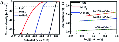
We further investigated the HER performance of the A-MoSx in 1.0 M KOH. It only requires 356 mV to achieve 10 mA cm−2 (Fig. 4a) and shows a Tafel slope of 101 mV dec−1 (Fig. 4b) in basic media. These values compare favorably to the original MoS2, which displays an overpotential of 551 mV at j = 10 mA cm−2 and a Tafel slope of 165 mV dec−1. These results suggest an enhanced HER activity. According to the Tafel plots, the HER exchange current density for the A-MoSx is 6.30 × 10⁻³ mA cm−2, a slightly higher than the original MoS2 (5.01 × 10⁻³ mA cm−2). The I–V curves of the A-MoSx and MoS2 at scan rates from 5 to 300 mV s−1 is also tested (Fig. 5). The A-MoSx almost remains unchanged at different scan rates, demonstrating its excellent stability. It should be noted that molybdenum-sulfide-based electrocatalysts rarely reported to apply to HER in basic media because of the relatively lower activity in basic media due to the limited amount of hydrogen ions for proton reduction reaction in basic solution. Thus, our work represents a new break for advanced A-MoSx electrocatalysts in a basic media for HER.
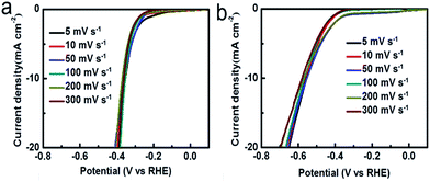 | ||
| Fig. 5 The polarization curves of (a) the A-MoSx; (b) MoS2 with scan rates from 5 to 300 mV s−1 in 1.0 M KOH. | ||
The enhanced HER activity of A-MoSx can be attributed to the following reasons. The A-MoSx shows the better conductivity. That enables simple and effective electrical transfer to minimize parasitic ohmic loss. Also, low resistance correspond to a more favorable HER kinetic over the A-MoSx catalysts. Most importantly, after arc-melting, large number of defects were created in the A-MoSx. Thus it is effective to introduce more active sites for H+ adsorption via the formation of defects, leading to an improvement of the hydrogen evolution activity.
In conclusion, we have prepared a defective A-MoSx catalyst, showing excellent HER active both in acid and basic media. The catalyst mainly consists of Mo2S3 and Mo3S4 and exhibits a superior activity in acid condition, with a low overpotential of 156 mV at j = 10 mA cm−2, Tafel slope of 58 mV dec−1, and a large exchange current density of 0.40 mA cm−2. The results surpass most of MoS2 catalysts previously reported. Our work demonstrates that the new molybdenum multisulfide hybrid material can be used as an active, low-cost, non-noble metal electrocatalyst for the HER and the arc-melting method is simple and straightforward technique to implant defects, which could be easily extended to synthesize other catalysts for the HER.
Acknowledgements
This work was supported by National Basic Research of China (Grant No. 2015CB932500 and 2013CB632702) and NSF of China (Grant No. 51302141 and 61274015).Notes and references
- (a) H. M. Chen, C. K. Chen, R.-S. Liu, L. Zhang, J. Zhang and D. P. Wilkinson, Chem. Soc. Rev., 2012, 41, 5654 RSC; (b) H. A. Gasteiger and N. M. Marković, Science, 2009, 324, 48 CrossRef CAS PubMed; (c) H. I. Karunadasa, C. J. Chang and J. R. Long, Nature, 2010, 464, 1329 CrossRef CAS PubMed; (d) M. G. Walter, E. L. Warren, J. R. McKone, S. W. Boettcher, Q. Mi, E. A. Santori and N. S. Lewis, Chem. Rev., 2010, 110, 6446 CrossRef CAS PubMed; (e) M. S. Dresselhaus and I. L. Thomas, Nature, 2001, 414, 332 CrossRef CAS PubMed; (f) M. Zeng and Y. Li, J. Mater. Chem. A, 2015, 3, 14942 RSC; (g) X. Zou and Y. Zhang, Chem. Soc. Rev., 2015, 44, 5148 RSC; (h) Y. Jiao, Y. Zheng, M. Jaroniec and S. Z. Qiao, Chem. Soc. Rev., 2015, 44, 2060 RSC.
- (a) V. R. Stamenkovic, B. S. Mun, M. Arenz, K. J. J. Mayrhofer, C. A. Lucas, G. Wang, P. N. Ross and N. M. Markovic, Nat. Mater., 2007, 6, 241 CrossRef CAS PubMed; (b) H. B. Gray, Nat. Chem., 2009, 1, 7 CrossRef CAS PubMed; (c) M. Mavrikakis, Nat. Mater., 2006, 5, 847 CrossRef CAS PubMed; (d) W.-F. Chen, K. Sasaki, C. Ma, A. I. Frenkel, N. Marinkovic, J. T. Muckerman, Y. Zhu and R. R. Adzic, Angew. Chem., Int. Ed., 2012, 51, 6131 CrossRef CAS PubMed.
- (a) C. G. Morales-Guio, L.-A. Stern and X. Hu, Chem. Soc. Rev., 2014, 43, 6555 RSC; (b) M. S. Faber and S. Jin, Energy Environ. Sci., 2014, 7, 3519 RSC; (c) H. Vrubel and X. Hu, Angew. Chem., Int. Ed., 2012, 51, 12703 CrossRef CAS PubMed.
- (a) E. J. Popczun, C. G. Read, C. W. Roske, N. S. Lewis and R. E. Schaak, Angew. Chem., Int. Ed., 2014, 53, 5427 CrossRef CAS PubMed; (b) X. Wang, Y. V. Kolen'ko, X. Q. Bao, K. Kovnir and L. Liu, Angew. Chem., Int. Ed., 2015, 54, 8188 CrossRef CAS PubMed; (c) Q. Lu, G. S. Hutchings, W. Yu, Y. Zhou, R. V. Forest, R. Tao, J. Rosen, B. T. Yonemoto, Z. Cao, H. Zheng, J. Q. Xiao, F. Jiao and J. G. Chen, Nat. Commun., 2015, 6, 6567 CrossRef CAS PubMed; (d) J. Tian, Q. Liu, A. M. Asiri and X. Sun, J. Am. Chem. Soc., 2014, 136, 7587 CrossRef CAS PubMed; (e) C. He and J. Tao, Chem. Commun., 2015, 51, 8323 RSC.
- (a) A. B. Laursen, S. Kegnaes, S. Dahl and I. Chorkendorff, Energy Environ. Sci., 2012, 5, 5577 RSC; (b) M. Chhowalla, H. S. Shin, G. Eda, L. J. Li, K. P. Loh and H. Zhang, Nat. Chem., 2013, 5, 263 CrossRef PubMed.
- (a) D. Merki and X. Hu, Energy Environ. Sci., 2011, 4, 3878 RSC; (b) B. Hinnemann, P. G. Moses, J. Bonde, K. P. Jørgensen, J. H. Nielsen, S. Horch, I. Chorkendorff and J. K. Nørskov, J. Am. Chem. Soc., 2005, 127, 5308 CrossRef CAS PubMed; (c) D. Kong, H. Wang, J. J. Cha, M. Pasta, K. J. Koski, J. Yao and Y. Cui, Nano Lett., 2013, 13, 1341 CrossRef CAS PubMed; (d) J. Xie, H. Zhang, S. Li, R. Wang, X. Sun, M. Zhou, J. Zhou, X. W. Lou and Y. Xie, Adv. Mater., 2013, 25, 5807 CrossRef CAS PubMed; (e) H. Wang, C. Tsai, D. Kong, K. Chan, F. Abild-Pedersen, J. K. Nørskov and Y. Cui, Nano Res., 2015, 8, 566 CrossRef CAS.
- Y. Li, H. Wang, L. Xie, Y. Liang, G. Hong and H. Dai, J. Am. Chem. Soc., 2011, 133, 7296 CrossRef CAS PubMed.
- H. Li, C. Tsai, A. L. Koh, L. Cai, A. W. Contryman, A. H. Fragapane, J. Zhao, H. S. Han, H. C. Manoharan, F. Abild-Pedersen, J. K. Norskov and X. Zheng, Nat. Mater., 2016, 15, 48 CrossRef CAS PubMed.
- (a) Y. H. Chang, C. T. Lin, T. Y. Chen, C. L. Hsu, Y. H. Lee, W. Zhang, K. H. Wei and L. J. Li, Adv. Mater., 2013, 25, 756 CrossRef CAS PubMed; (b) A. B. Laursen, P. C. Vesborg and I. Chorkendorff, Chem. Commun., 2013, 49, 4965 RSC.
- D. Merki, S. Fierro, H. Vrubel and X. Hu, Chem. Sci., 2011, 2, 1262 RSC.
- J. Staszak-Jirkovský, C. D. Malliakas, P. P. Lopes, N. Danilovic, S. S. Kota, K.-C. Chang, B. Genorio, D. Strmcnik, V. R. Stamenkovic, M. G. Kanatzidis and N. M. Markovic, Nat. Mater., 2016, 15, 197 CrossRef PubMed.
- (a) Z. Chen, D. Cummins, B. N. Reinecke, E. Clark, M. K. Sunkara and T. F. Jaramillo, Nano Lett., 2011, 11, 4168 CrossRef CAS PubMed; (b) T. F. Jaramillo, K. P. Jørgensen, J. Bonde, J. H. Nielsen, S. Horch and I. Chorkendorff, Science, 2007, 317, 100 CrossRef CAS PubMed.
- G. Ou, D. Li, W. Pan, Q. Zhang, B. Xu, L. Gu, C. Nan and H. Wu, Adv. Mater., 2015, 27, 2589 CrossRef CAS PubMed.
- L. A. Jacobson and J. McKittrick, Mater. Sci. Eng., R, 1994, 11, 355 CrossRef.
- (a) G. Ye, Y. Gong, J. Lin, B. Li, Y. He, S. T. Pantelides, W. Zhou, R. Vajtai and P. M. Ajayan, Nano Lett., 2016, 16, 1079 Search PubMed; (b) N. Kang, H. P. Paudel, M. N. Leuenberger, L. Tetard and S. I. Khondaker, J. Phys. Chem. C, 2014, 118, 21258 CrossRef CAS.
- M. R. Islam, N. Kang, U. Bhanu, H. P. Paudel, M. Erementchouk, L. Tetard, M. N. Leuenberger and S. I. Khondaker, Nanoscale, 2014, 6, 10033 RSC.
- B. Cao, G. M. Veith, J. C. Neuefeind, R. R. Adzic and P. G. Khalifah, J. Am. Chem. Soc., 2013, 135, 19186 CrossRef CAS PubMed.
- S. McDonnell, R. Addou, C. Buie, R. M. Wallace and C. L. Hinkle, ACS Nano, 2014, 8, 2880 CrossRef CAS PubMed.
- (a) D. J. Li, U. N. Maiti, J. Lim, D. S. Choi, W. J. Lee, Y. Oh, G. Y. Lee and S. O. Kim, Nano Lett., 2014, 14, 1228 CrossRef CAS PubMed; (b) J. D. Benck, Z. Chen, L. Y. Kuritzky, A. J. Forman and T. F. Jaramillo, ACS Catal., 2012, 2, 1916 CrossRef CAS; (c) J. Kibsgaard, Z. Chen, B. N. Reinecke and T. F. Jaramillo, Nat. Mater., 2012, 11, 963 CrossRef CAS PubMed.
- Y. Yan, B. Xia, N. Li, Z. Xu, A. Fisher and X. Wang, J. Mater. Chem. A, 2015, 3, 131 CAS.
- (a) X. Xie, L. Lin, R.-Y. Liu, Y.-F. Jiang, Q. Zhu and A.-W. Xu, J. Mater. Chem. A, 2015, 3, 8055 RSC; (b) X. Xie, R. Yu, N. Xue, A. B. Yousaf, H. Du, K. Liang, N. Jiang and A.-W. Xu, J. Mater. Chem. A, 2016, 4, 1647 RSC; (c) C.-Z. Yuan, Y.-F. Jiang, Z. Wang, X. Xie, Z.-K. Yang, A. B. Yousaf and A.-W. Xu, J. Mater. Chem. A, 2016, 4, 8155 RSC.
- Y. Yan, B. Xia, N. Li, Z. Xu, A. Fisher and X. Wang, J. Mater. Chem. A, 2015, 3, 131 CAS.
Footnotes |
| † Electronic supplementary information (ESI) available: Experimental section and additional experimental data. See DOI: 10.1039/c6ra18106f |
| ‡ L. F. Zhang and G. Ou contributed equally to this work. |
| This journal is © The Royal Society of Chemistry 2016 |

