 Open Access Article
Creative Commons Attribution 3.0 Unported Licence
Lithium intercalation in the surface region of an LiNi1/3Mn1/3Co1/3O2 cathode through different crystal planes†
Masaaki
Hirayama
*a,
Machiko
Abe
ab,
Sou
Taminato
a,
Yuya
Araki
a,
Kota
Suzuki
a and
Ryoji
Kanno
a
aDepartment of Chemical Science and Engineering, School of Materials and Chemical Technology, Tokyo Institute of Technology, 4259 Nagatsuta, Midori-ku, Yokohama 226-8502, Japan. E-mail: hirayama@echem.titech.ac.jp; Fax: +81-459245403; Tel: +81-459245403
bBattery Evaluation & Analysis Dept., Battery Material Engineering & Research Div., Toyota Motor Corporation, 1 Toyota, Aichi 471-8572, Japan
First published on 15th August 2016
Abstract
Epitaxial LiNi1/3Co1/3Mn1/3O2 film electrodes with orientations of (104), (1−18) and (003) were fabricated on SrRuO3/SrTiO3 by pulsed laser deposition. The films have a thickness of 23.8 to 25.0 nm and a flat surface with a roughness of approximately 2 nm, which offered a model system for clarifying the reaction plane dependencies of lithium intercalation at the LiNi1/3Co1/3Mn1/3O2 surface. All reaction planes delivered reversible lithium intercalation for electrochemical charging–discharging between 3.0 V and 4.3 V (vs. Li/Li+). The (104) surface exhibited reversible behavior at a higher operation voltage between 3.0 V and 4.5 V, but the (1−18) and (003) planes showed fading of the discharge capacity and average discharge voltage. The anisotropic stability of the surface region indicates the importance of crystallographic facet control for the development of an LiNi1/3Co1/3Mn1/3O2 cathode with high cycle stability.
1. Introduction
LiNi1/3Co1/3Mn1/3O2 with a layered rocksalt structure is one of the most promising cathode materials in lithium ion batteries due to its high discharge capacity, cost competitiveness, and high safety over conventional LiCoO2.1–3 The LiNi1/3Co1/3Mn1/3O2 delivers a reversible lattice change during lithium (de)intercalation under high-voltage operation to 4.5 V,4 which is expected for use in high-energy-density batteries for large-scale applications such as electric vehicles or hybrid electric vehicles. However, the LiNi1/3Co1/3Mn1/3O2 suffers from severe capacity fading and poor high-rate capability, which is associated with poor electronic conductivity and side reactions with electrolyte species at the electrode and electrolyte interface.5 A cubic rock-salt-type phase is typically formed near the surface of LiNi1/3Co1/3Mn1/3O2 and has been considered to increase the reaction resistance at the electrochemical interface, resulting in the fading of the charge–discharge capacity.6,7 As with other cathode materials, it has been proposed that surface coating with oxide materials is an effective way to stabilize the LiNi1/3Co1/3Mn1/3O2 surface.6–11 A recent study using scanning transmission electron microscopy demonstrated that the formation of the rocksalt-type phase in the surface region was suppressed by an aluminum oxide coating on LiNi1/3Co1/3Mn1/3O2.7 However, the detailed mechanisms of fading and stabilization in the surface region are still unclear due to insufficient experimental information for the elucidation of the complicated reaction field and its associated reaction parameters.Epitaxial thin-film electrodes have the following features for clarifying the surface reaction mechanism in lithium ion batteries.12–17 First, they have very flat surfaces with roughness of approximately 2 nm and include no additives such as conductive carbon and binders, which simplify surface reactions. Second, the film thickness can be controlled in the range of 10 to 100 nm; a very thin film can function as a surface-enhanced electrode. Third, the reaction field is restricted by the lattice orientation, which can provide information on anisotropic reaction mechanisms. Although epitaxial growths of some layered rocksalt oxides have been reported,12,18–24 there have been no reports of the successful synthesis of an epitaxial LiNi1/3Co1/3Mn1/3O2 film electrode. Previously, LiNi1/3Co1/3Mn1/3O2 thin-films were synthesized by magnetron sputtering and PLD methods on Pt/Si, Au, and Li1+x+yAlxTi2−xSiyP3−yO12 substrates.25,26 These films were in a polycrystalline state with an oriented character in the (003) plane26 or with random orientations.25 Furthermore, they included amorphous LiNi1/3Co1/3Mn1/3O2 owing to low synthetic temperatures, below 500 °C. Recently, it has been reported that layered rock-salt-type Li(Mn,Co,Ni)O2(1−18) films were epitaxially grown on an Nb:SrTiO3(110) single crystal by pulsed laser deposition.27 However, the composition of the films could not be determined owing to contamination with a large amount of disordered spinel and/or rock-salt-type phases, and thus the charge–discharge properties were not consistent with those observed for polycrystalline LiNi1/3Co1/3Mn1/3O2 electrodes. Furthermore, no other orientations of epitaxial films were fabricated.
In this work, we investigated synthetic conditions using pulsed laser deposition and successfully fabricated epitaxial LiNi1/3Co1/3Mn1/3O2 films with orientations of (1−18), (104), and (003) on Nb:SrTiO3(110), (100), and (111) substrates, respectively. The structure and chemical composition of the epitaxial films were confirmed by X-ray diffraction (XRD), X-ray reflectivity (XRR), inductively-coupled plasma mass spectrometry (ICP-MS), and X-ray absorption near-edge structure (XANES) measurements. The lithium intercalation properties of the LiNi1/3Co1/3Mn1/3O2 surface were examined by charge–discharge measurements using epitaxial LiNi1/3Co1/3Mn1/3O2 film model electrodes with a thickness of approximately 25 nm. The anisotropy of lithium intercalation in the surface region of LiNi1/3Co1/3Mn1/3O2 is discussed with respect to the reaction plane dependence of the charge–discharge capacity and the cycle retention of the model electrodes.
2. Experimental
LiNi1/3Co1/3Mn1/3O2 and SrRuO3 films were synthesized by pulsed laser deposition (PLD) using a PLD system consisting in a KrF excimer laser (Lambda Physik, COMPex201) with a wavelength of 248 nm and a vacuum chamber (PLAD-312, AOV Inc.). Single crystals of 0.5 wt% Nb-doped SrTiO3 (10 × 10 × 0.5 mm, Crystal Base Co., Ltd.) were used as the substrate. The SrRuO3(100), (110), and (111) films were epitaxially grown on the Nb:SrTiO3(100), (110), and (111) substrates, respectively, to improve the electronic conduction for electrochemical investigation.16 The synthetic conditions were as follows: oxygen pressure, pO2 = 15 Pa; distance between substrate and target, d = 60 mm; laser frequency, f = 5 Hz; deposition time, td = 20 min; energy density, E = 50 mJ; temperature, t = 700 °C. After the deposition of the SrRuO3 layer, LiNi1/3Co1/3Mn1/3O2 films were stacked using the following conditions, which were optimized based on the results of a previous study:27 oxygen pressure, pO2 = 75 Pa; distance between substrate and target, d = 60 mm; laser frequency, f = 3 Hz; deposition time, td = 10 min; energy density, E = 120 mJ; temperature, t = 650 °C.XRD and XRR measurements were performed in air using a thin-film X-ray diffractometer (Rigaku ATX-G) with Cu Kα1 radiation. The film orientation was determined from XRD patterns collected along out-of-plane and in-plane directions. The film thickness, X-ray scattering length density (SLD), and roughness were determined by XRR analysis using Parratt32 software.28,29 XRR spectra were plotted as a function of the scattering vector, Qz = 4π![[thin space (1/6-em)]](https://www.rsc.org/images/entities/char_2009.gif) sin
sin![[thin space (1/6-em)]](https://www.rsc.org/images/entities/char_2009.gif) θ/λ, where λ is the X-ray wavelength (1.541 Å) and θ is the incident angle. Elemental ratios of Li, Ni, Co, and Mn in the thin films were determined using ICP-MS (Agilent 7500cs, Agilent Technologies) from samples dissolved in aqua regia diluted with ultrapure water at 100 °C for 30 minutes. XANES measurements were performed in the fluorescence mode, using a germanium single-element solid-state detector installed at SPring-8 BL14B2, and data were collected at an oblique incidence angle of 4°. Pre-edge background and post-edge normalizations of spectra to unity were performed using the ATHENA software package.30
θ/λ, where λ is the X-ray wavelength (1.541 Å) and θ is the incident angle. Elemental ratios of Li, Ni, Co, and Mn in the thin films were determined using ICP-MS (Agilent 7500cs, Agilent Technologies) from samples dissolved in aqua regia diluted with ultrapure water at 100 °C for 30 minutes. XANES measurements were performed in the fluorescence mode, using a germanium single-element solid-state detector installed at SPring-8 BL14B2, and data were collected at an oblique incidence angle of 4°. Pre-edge background and post-edge normalizations of spectra to unity were performed using the ATHENA software package.30
Charge/discharge characteristics were examined using a 2032-type coin cell. The cells were assembled inside an argon-filled glove box using lithium metal as counter electrode and the LiNi1/3Co1/3Mn1/3O2 film as the working electrode. The electrolyte comprised ethylene carbonate–diethyl carbonate with a volume ratio of 3![[thin space (1/6-em)]](https://www.rsc.org/images/entities/char_2009.gif) :
:![[thin space (1/6-em)]](https://www.rsc.org/images/entities/char_2009.gif) 7 (EC/DEC; Kishida Chemical Co., Ltd., >99.5%) as the solvent and 1.0 mol dm−3 LiPF6 as the supporting electrolyte. The charge–discharge characteristics were examined at room temperature using a multi-channel potentio/galvanostat (TOSCAT 3100). The cut-off voltages were 3.0 and 4.3 V, 3.0 and 4.5 V, and 2.0 and 4.5 V for discharge and charge, respectively. The charge–discharge capacities of the cells were calculated by taking into account the area over which the film was deposited (10 × 7 mm), the film thickness and the theoretical density of LiNi1/3Co1/3Mn1/3O2 (4.77 g cm−3). The constant current applied was 1 μA.
7 (EC/DEC; Kishida Chemical Co., Ltd., >99.5%) as the solvent and 1.0 mol dm−3 LiPF6 as the supporting electrolyte. The charge–discharge characteristics were examined at room temperature using a multi-channel potentio/galvanostat (TOSCAT 3100). The cut-off voltages were 3.0 and 4.3 V, 3.0 and 4.5 V, and 2.0 and 4.5 V for discharge and charge, respectively. The charge–discharge capacities of the cells were calculated by taking into account the area over which the film was deposited (10 × 7 mm), the film thickness and the theoretical density of LiNi1/3Co1/3Mn1/3O2 (4.77 g cm−3). The constant current applied was 1 μA.
3. Results and discussion
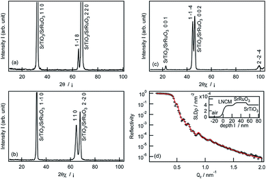
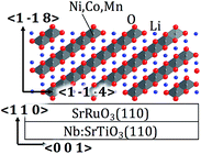
Fig. 1a–c depicts the XRD patterns of a pristine LiNi1/3Co1/3Mn1/3O2 film deposited on the SrRuO3/Nb:SrTiO3(110) substrate. A diffraction peak was observed at 64.7° in the out-of-plane SrTiO3 〈110〉 direction (Fig. 1a), which can be indexed as the 1−18 reflection of the layered rock-salt-type phase with space group R![[3 with combining macron]](https://www.rsc.org/images/entities/char_0033_0304.gif) m.2,31 In the case of the in-plane XRD patterns, the 110 and 1−1−4 diffraction peaks were observed at 64.7° and 44.7° along the SrTiO3[1−10] and [010] directions, respectively (Fig. 1b and c). These results confirmed epitaxial growth of the LiNi1/3Co1/3Mn1/3O2(1−18) film on the SrRuO3/Nb:SrTiO3(110) substrate. Fig. 1d illustrates the XRR analysis result, the fitting model, and the X-ray SLD profile of the pristine LiNi1/3Co1/3Mn1/3O2(1−18) film. A two-layer model consisting of the LiNi1/3Co1/3Mn1/3O2 film and the SrRuO3 film on the Nb:SrTiO3 substrate closely fitted the reflectivity curve. The thickness, surface roughness, and SLD value of the LiNi1/3Co1/3Mn1/3O2(1−18) film were refined to 25.0 nm, 2.2 nm, and 3.78 × 10⁻³ nm−2, respectively (see Table S1 in ESI†). The SLD value was consistent with that expected for stoichiometric LiNi1/3Co1/3Mn1/3O2 (3.81 × 10⁻³ nm−2).31 The flat SLD profile of the LiNi1/3Co1/3Mn1/3O2 layer indicated a uniform film composition in the depth direction.
m.2,31 In the case of the in-plane XRD patterns, the 110 and 1−1−4 diffraction peaks were observed at 64.7° and 44.7° along the SrTiO3[1−10] and [010] directions, respectively (Fig. 1b and c). These results confirmed epitaxial growth of the LiNi1/3Co1/3Mn1/3O2(1−18) film on the SrRuO3/Nb:SrTiO3(110) substrate. Fig. 1d illustrates the XRR analysis result, the fitting model, and the X-ray SLD profile of the pristine LiNi1/3Co1/3Mn1/3O2(1−18) film. A two-layer model consisting of the LiNi1/3Co1/3Mn1/3O2 film and the SrRuO3 film on the Nb:SrTiO3 substrate closely fitted the reflectivity curve. The thickness, surface roughness, and SLD value of the LiNi1/3Co1/3Mn1/3O2(1−18) film were refined to 25.0 nm, 2.2 nm, and 3.78 × 10⁻³ nm−2, respectively (see Table S1 in ESI†). The SLD value was consistent with that expected for stoichiometric LiNi1/3Co1/3Mn1/3O2 (3.81 × 10⁻³ nm−2).31 The flat SLD profile of the LiNi1/3Co1/3Mn1/3O2 layer indicated a uniform film composition in the depth direction.
The film orientation of (1−18) on the SrRuO3/Nb:SrTiO3(110) was consistent with that for Li–(Mn,Co,Ni)–O films reported previously.27 The LiNi1/3Co1/3Mn1/3O2 film fabricated in this study exhibited no diffraction peaks of other phases (except for those of SrRuO3/Nb:SrTiO3) in the out-of-plane XRD pattern, although a 220 diffraction peak for a disordered spinel phase was observed at around 32° in the XRD patterns of the Li–(Mn,Co,Ni)–O(1−18) film. This indicates that the LiNi1/3Co1/3Mn1/3O2(1−18) film contained a much lower amount of the spinel-phase impurity. Table 1 lists the d values, intensities, and full width at half maximum (FWHM) values of the out-of-plane 1−18 and in-plane 110 diffraction peaks observed for the epitaxial films fabricated in this study and in the previous study.27 The positions and intensities of the 1−18 and 110 peaks were normalized using the values of the 110 and 2−20 peaks of the Nb:SrTiO3, respectively. The 1−18 and 110 diffraction peaks of the LiNi1/3Co1/3Mn1/3O2 film had higher relative intensities than those of the Li–(Mn,Co,Ni)–O film, whereas no considerable difference in the FWHM value was observed. These XRD results demonstrated the formation of a well-crystallized LiNi1/3Co1/3Mn1/3O2(1−18) film with high purity, compared to the Li–(Mn,Co,Ni)–O film. A previous report proposed that the structural transformation from the layered rock salt to the cubic spinel is caused by lithium loss during the high temperature PLD process.12,18,20,27,32 In this study, an Li1.5Ni1/3Co1/3Mn1/3O2 target with a high lithium content (50% excess) was used, compared to that used in the previous study (Li1.3Ni1/3Co1/3Mn1/3O2). The excess lithium in the target could compensate for the lithium loss, resulting in a LiNi1/3Co1/3Mn1/3O2(1−18) film with high purity. Furthermore, the higher lithium content in the target enabled us to apply a high substrate temperature of 650 °C, which was higher than that in the previous study (600 °C). This could contribute to the high crystallinity of the film. The purity and crystallinity of the LiNi1/3Co1/3Mn1/3O2 films were considerably improved by optimizing the synthetic conditions.
| This study | Previous study27 | |||
|---|---|---|---|---|
| 1−18 | 110 | 1−18 | 110 | |
| a The intensities of the 1−18 and 110 diffraction peaks were normalized using the values of the 110 and 2−20 diffraction peaks of Nb:SrTiO3, respectively. | ||||
| d value [Å] | 1.439 | 1.438 | 1.445 | 1.452 |
| Relative intensity [—]a | 2.50 × 10⁻⁴ | 0.654 | 8.16 × 10⁻⁵ | 0.126 |
| FWHM [°] | 0.447 | 0.915 | 0.466 | 0.962 |
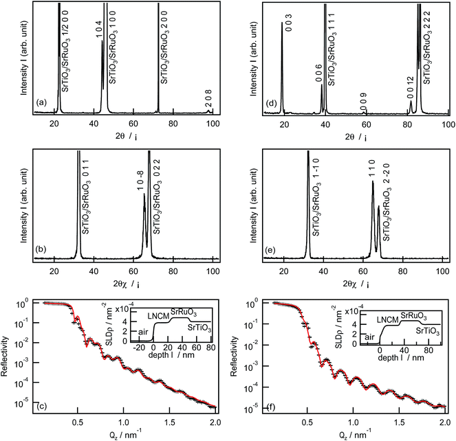
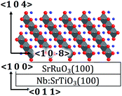
LiNi1/3Co1/3Mn1/3O2 films were synthesized on the SrRuO3/Nb:SrTiO3(100) and SrRuO3/Nb:SrTiO3(111) substrates under the same PLD conditions used for the LiNi1/3Co1/3Mn1/3O2(1−18) film. The XRD patterns and XRR analysis results of the LiNi1/3Co1/3Mn1/3O2 films are shown in Fig. 2. The LiNi1/3Co1/3Mn1/3O2 film deposited on the (100) substrate had h04h and h0−8h orientations along the out-of-plane [100] and in-plane [011] directions of the Nb:SrTiO3 substrate, respectively (Fig. 2a and b). No other diffraction peaks of the film were observed in the XRD patterns, which indicates the epitaxial growth of the LiNi1/3Co1/3Mn1/3O2(104) film. The same structural model provided a good fitting result for the XRR spectrum (Fig. 2c). The thickness, surface roughness, and X-ray SLD value of the LiNi1/3Co1/3Mn1/3O2(104) film were refined to 23.4 nm, 1.8 nm, and 3.76 × 10⁻³ nm−2, respectively. The LiNi1/3Co1/3Mn1/3O2 film synthesized on the SrRuO3/Nb:SrTiO3(111) substrate also showed epitaxial growth with orientations of 00l and hh0 along the out-of-plane [111] and in-plane [1−10] directions of the Nb:SrTiO3 substrate, respectively (Fig. 2d and e). From the XRR analysis result (Fig. 2f), the thickness, surface roughness, and X-ray SLD value of the LiNi1/3Co1/3Mn1/3O2(003) film were refined to 29.1 nm, 2.3 nm, and 3.78 × 10⁻³ nm−2, respectively.
Table 2 summarizes the orientations and structural parameters of the epitaxial LiNi1/3Co1/3Mn1/3O2 films with (1−18), (104), and (003) orientations, fabricated on SrRuO3/Nb:SrTiO3. The (1−18), (104), and (003) films had similar lattice parameters, thicknesses (23.4–29.1 nm), SLD values (4.73–4.78 nm−2), and surface roughnesses (1.8–2.3 nm), indicating similar structures and chemical compositions, which are independent of the orientations. The molar ratio of Li, Ni, Co, and Mn atoms in the LiNi1/3Co1/3Mn1/3O2(104) film was estimated by ICP-MS analysis to be Li![[thin space (1/6-em)]](https://www.rsc.org/images/entities/char_2009.gif) :
:![[thin space (1/6-em)]](https://www.rsc.org/images/entities/char_2009.gif) Ni
Ni![[thin space (1/6-em)]](https://www.rsc.org/images/entities/char_2009.gif) :
:![[thin space (1/6-em)]](https://www.rsc.org/images/entities/char_2009.gif) Co
Co![[thin space (1/6-em)]](https://www.rsc.org/images/entities/char_2009.gif) :
:![[thin space (1/6-em)]](https://www.rsc.org/images/entities/char_2009.gif) Mn = 49.8
Mn = 49.8![[thin space (1/6-em)]](https://www.rsc.org/images/entities/char_2009.gif) :
:![[thin space (1/6-em)]](https://www.rsc.org/images/entities/char_2009.gif) 15.9
15.9![[thin space (1/6-em)]](https://www.rsc.org/images/entities/char_2009.gif) :
:![[thin space (1/6-em)]](https://www.rsc.org/images/entities/char_2009.gif) 16.8
16.8![[thin space (1/6-em)]](https://www.rsc.org/images/entities/char_2009.gif) :
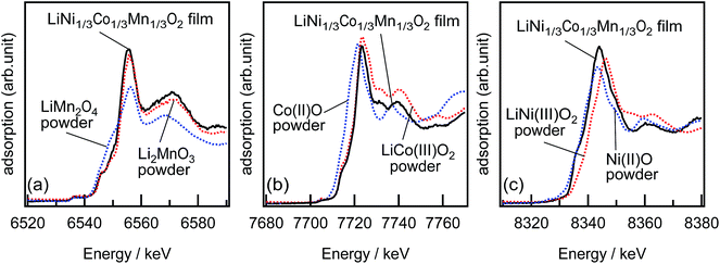
:![[thin space (1/6-em)]](https://www.rsc.org/images/entities/char_2009.gif) 17.5. The film composition was calculated to be Li0.99±0.03Ni0.32±0.01Co0.33±0.01Mn0.35±0.01O2, when the total moles of Ni, Co, and Mn atoms was normalized to 1. No significant changes in the composition was observed for the (1−18) and (003) films. Furthermore, the oxidation states of Ni, Co, and Mn ions in the LiNi1/3Co1/3Mn1/3O2 film were investigated by XANES. Fig. 3 shows the Mn-K, Co-K, and Ni-K edges XANES spectra obtained from a LiNi1/3Co1/3Mn1/3O2(104) film and polycrystalline standard materials. The XANES spectra indicated that the oxidation states of Ni, Co, and Mn were identical to those of polycrystalline NiO, LiCoO2, and Li2MnO3, respectively. The ICP and XANES results confirmed the growth of the epitaxial LiNiII1/3CoIII1/3MnIV1/3O2 films with no lithium deficiency.
17.5. The film composition was calculated to be Li0.99±0.03Ni0.32±0.01Co0.33±0.01Mn0.35±0.01O2, when the total moles of Ni, Co, and Mn atoms was normalized to 1. No significant changes in the composition was observed for the (1−18) and (003) films. Furthermore, the oxidation states of Ni, Co, and Mn ions in the LiNi1/3Co1/3Mn1/3O2 film were investigated by XANES. Fig. 3 shows the Mn-K, Co-K, and Ni-K edges XANES spectra obtained from a LiNi1/3Co1/3Mn1/3O2(104) film and polycrystalline standard materials. The XANES spectra indicated that the oxidation states of Ni, Co, and Mn were identical to those of polycrystalline NiO, LiCoO2, and Li2MnO3, respectively. The ICP and XANES results confirmed the growth of the epitaxial LiNiII1/3CoIII1/3MnIV1/3O2 films with no lithium deficiency.
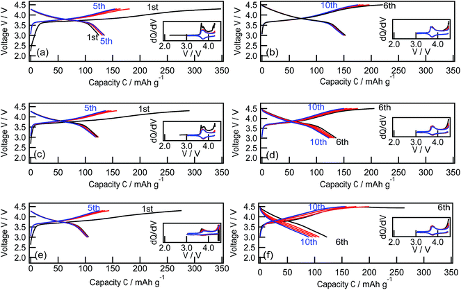
Fig. 4 depicts the charge–discharge curves and dQ/dV curves of epitaxial LiNi1/3Co1/3Mn1/3O2 films with (1−18), (104), and (003) reaction planes. The electrochemical measurements were conducted between 3.0 V and 4.3 V during the initial five cycles and between 3.0 V and 4.5 V from the 6th to the 10th cycles. For cut-off voltages of 3.0 and 4.3 V, the potential profiles are almost independent of the reaction plane. During the charging process, the voltage rapidly increased to approximately 3.6 V and rose gradually to 4.3 V. The voltage gradually decreased to approximately 3.6 V. Then rapidly decreased to 3.0 V. Reversible oxidation and reduction peaks were observed at around 3.7 V in the dQ/dV curves, which corresponded to lithium deintercalation and intercalation from/into the LiNi1/3Co1/3Mn1/3O2 lattice.33,34 The first charge/discharge capacities were 345/124 mA h g−1, 291/123 mA h g−1, and 275/106 mA h g−1, for the (1−18), (104), and (003) films, respectively. Large irreversible capacities of over 150 mA h g−1 were observed for all films, which is a typical feature of nanosized film electrodes because of side reactions that are quite prominent due to the small amount of active material.16,23,35 The irreversible capacity gradually decreased during subsequent cycles. When the higher cut-off voltage was changed to 4.5 V at the 6th cycle, the LiNi1/3Co1/3Mn1/3O2(1−18), (104), and (003) films delivered higher discharge capacities of 153, 136, and 122 mA h g−1, respectively. A larger amount of lithium was deintercalated from the LiNi1/3Co1/3Mn1/3O2 lattice at above 4.3 V during the charging process and then reversibly intercalated into it during the discharging process.2,3
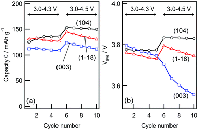
Fig. 5 depicts the cycle retention of the discharge capacity and the average discharge voltage of the (1−18), (104), and (003) films, which were analysed using the charge–discharge curves shown in Fig. 4. The (104) film exhibited no significant fading of the discharge capacity or the average discharge voltage under battery operation between 3.0 and 4.3 V, whereas the (1−18) and (003) films showed a small decrease in capacity and discharge voltage during the initial five cycles. This behaviour was clearly observed when the batteries were operated between 3.0 and 4.5 V. In contrast, the discharge capacity of the (104) film showed a small change from 140 (6th cycle) to 137 mA h g−1 (10th cycle), and the average discharge potential remained stable at 3.83 V. The (1−18) film showed a relatively large decrease in the discharge capacity of 15 mA h g−1 and the average discharge voltage of 50 mV from the 6th to the 10th cycles. Furthermore, a drastic decrease in the average discharge voltage (150 mV) was observed for the (003) film with a simultaneous decrease in the discharge capacity (15 mA h g−1). These results clarified that the electrochemical stability of the LiNi1/3Co1/3Mn1/3O2 surface depends on the reaction plane and operating voltages.
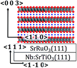
The crystal structure of LiNi1/3Co1/3Mn1/3O2 consists in cubic close-packed oxide ions with the basal planes of octahedral interstices filled alternately by Li ions and by Ni1/3, Co1/3 and Mn1/3 ions. Lithium ions are supposed to (de)intercalate into LiNi1/3Co1/3Mn1/3O2 through the infinite two-dimensional [LiO6] layers in the ab plane. Based on this intercalation mechanism, intercalative activity is expected for the epitaxial LiNi1/3Co1/3Mn1/3O2(1−18) and (104) films with the [LiO6] layers inclining to the electrolyte (Table 2). This speculation is consistent in that the (1−18) and (104) films delivered similar charge–discharge capacities between 3.0 and 4.3 V. However, the (104) film exhibited a superior charge–discharge capacity and cycle retention compared with the (1−18) film under battery operation between 3.0 and 4.5 V. This indicated the anisotropy of the electrochemical stability of the delithiated Li1−xNi1/3Co1/3Mn1/3O2 formed at above 4.3 V. The delithiated (1−18) surface might deteriorate by dissolution of transition metal ions, induced by side reactions with electrolyte species in high voltage regions, which has been generally observed for various electrode materials.6,14,36,37 In contrast to the (1−18) and (104) films, the (003) film with the [LiO6] layers parallel to the electrolyte is expected to exhibit poor lithium intercalative activity. However, the (003) film with the [LiO6] layers parallel to the electrolyte also exhibited reversible intercalative activity, although the charge–discharge capacities were smaller than those observed for the (1−18) and (104) films. From atomic force microscopy, islands with the maximum height of ≤5 nm were observed at the surface of the 29.1 nm-thick (003) film (see Fig. S1 in ESI†). Although the morphology indicates that the lithium (de)intercalation could proceed through the island edges in the top surface regions, it could not explain the discharge capacity of over 100 mA h g−1 observed for the (003) film. These results suggested lithium diffusion along the 〈001〉 direction in the LiNi1/3Co1/3Mn1/3O2(003) lattice. It has been reported that a layered rock-salt-type LiNi0.5Mn0.5O2 with a large degree of cation mixing between lithium and nickel sites exhibits reversible lithium intercalation.32 In the LiNi0.5Mn0.5O2 structure, lithium ions can diffuse along the c-axis between neighboring two-dimensional lithium layers, through the lithium sites in the transition metal layer. Thus, we can speculate that the LiNi1/3Co1/3Mn1/3O2(003) film has a certain amount of lithium is introduced in the transition metal layer by the cation mixing, which contributes to the lithium diffusion from the LiNi1/3Co1/3Mn1/3O2 lattice to the electrolyte through the (003) crystal plane. However, the (003) film showed severe fading of the discharge capacity and the discharge voltage under the high cut-off voltage operation, compared to the (104) and (1−18) films. This could be associated with the poor stability of the delithiated (003) surface. We can speculate, based on the lithium diffusion mechanism in the (003) film, that the lithium vacancies are introduced into the two-dimensional transitional layers when the state of charge increases above 4.3 V, which could destabilize the delithiated Li1−xNi1/3Co1/3Mn1/3O2 structure. The epitaxial-film model electrodes indicated the importance of crystallographic facet control for stable lithium intercalation in the surface region of the cathode, although further investigations based on crystal structure and oxidation state analyses are needed for elucidating the detailed surface reaction mechanism.
4. Conclusion
Epitaxial LiMn1/3Co1/3Ni1/3O2 films with different reaction planes of (104), (1−18) and (003) were successfully synthesized on SrRuO3/SrTiO3 by pulsed laser deposition using a target with a large excess of lithium. The films have a thickness between 23.8 and 25.0 nm and a flat surface with a roughness of below 2.0 nm. The similarity of the structures and compositions of the (104), (1−18), and (003) films provided a model system for a mechanistic study of the anisotropy of lithium intercalation. All the reaction planes delivered reversible lithium intercalation for electrochemical charging/discharging between 3.0 V and 4.3 V. The (104) plane exhibited reversible behavior between 3.0 V and 4.5 V, but the (1−18) and (003) planes showed a decrease in discharge capacity and average discharge voltage. The (104) plane was highly stable during the deintercalation process above 4.3 V, compared to the (1−18) and (003) planes. This indicates the importance of crystallographic facet control for practical use: polycrystalline LiMn1/3Co1/3Ni1/3O2 with a predominant (104) facet may deliver superior cycle stability.Acknowledgements
This work was supported by the Research and Development Initiative for Scientific Innovation of New Generation Battery (RISING Project) of the New Energy and Industrial Technology Development Organization (NEDO; Japan) and the Grant-in-Aid for Scientific Research (A, C) of Japan Society for the Promotion of Science (No. 25248051 and 16K05929). The synchrotron X-ray experiments were performed as projects approved by the Japan Synchrotron Radiation Research Institute (2014B1920).References
- Z. Lu, D. D. MacNeil and J. R. Dahn, Electrochem. Solid-State Lett., 2001, 4, A200–A203 CrossRef CAS.
- T. Ohzuku and Y. Makimura, Chem. Lett., 2001, 30, 642–643 CrossRef.
- N. Yabuuchi and T. Ohzuku, J. Power Sources, 2003, 119–121, 171–174 CrossRef CAS.
- N. Yabuuchi, Y. Makimura and T. Ohzuku, J. Electrochem. Soc., 2007, 154, A314–A321 CrossRef CAS.
- S. H. Park, C. S. Yoon, S. G. Kang, H. S. Kim, S. I. Moon and Y. K. Sun, Electrochim. Acta, 2004, 49, 557–563 CrossRef CAS.
- M. Shikano, H. Kobayashi, S. Koike, H. Sakaebe, Y. Saito, H. Hori, H. Kageyama and K. Tatsumi, J. Power Sources, 2011, 196, 6881–6883 CrossRef CAS.
- A. Yano, S. Aoyama, M. Shikano, H. Sakaebe, K. Tatsumi and Z. Ogumi, J. Electrochem. Soc., 2015, 162, A3137–A3144 CrossRef CAS.
- C. X. Ding, Y. C. Bai, X. Y. Feng and C. H. Chen, Solid State Ionics, 2011, 189, 69–73 CrossRef CAS.
- W. Luo and J. R. Dahn, J. Electrochem. Soc., 2011, 158, A428–A433 CrossRef CAS.
- X. Liu, H. Li, E. Yoo, M. Ishida and H. Zhou, Electrochim. Acta, 2012, 83, 253–258 CrossRef CAS.
- X. Li, H. Peng, M.-S. Wang, X. Zhao, P.-X. Huang, W. Yang, J. Xu, Z.-Q. Wang, M.-Z. Qu and Z.-L. Yu, ChemElectroChem, 2016, 3, 130–137 CrossRef CAS.
- M. Hirayama, N. Sonoyama, T. Abe, M. Minoura, M. Ito, D. Mori, A. Yamada, R. Kanno, T. Terashima, M. Takano, K. Tamura and J. Mizuki, J. Power Sources, 2007, 168, 493–500 CrossRef CAS.
- M. Hirayama, N. Sonoyama, M. Ito, M. Minoura, D. Mori, A. Yamada, K. Tamura, J. Mizuki and R. Kanno, J. Electrochem. Soc., 2007, 154, A1065–A1072 CrossRef CAS.
- M. Hirayama, H. Ido, K. Kim, W. Cho, K. Tamura, J. Mizuki and R. Kanno, J. Am. Chem. Soc., 2010, 132, 15268–15276 CrossRef CAS PubMed.
- M. Hirayama, M. Yonemura, K. Suzuki, N. Torikai, H. Smith, E. Watkinsand, J. Majewski and R. Kanno, Electrochemistry, 2010, 78, 413–415 CrossRef CAS.
- K. Suzuki, K. Kim, S. Taminato, M. Hirayama and R. Kanno, J. Power Sources, 2013, 226, 340–345 CrossRef CAS.
- M. Hirayama, Electrochemistry, 2015, 83, 701–706 CrossRef CAS.
- M. Hirayama, K. Sakamoto, T. Hiraide, D. Mori, A. Yamada, R. Kanno, N. Sonoyama, K. Tamura and J. Mizuki, Electrochim. Acta, 2007, 53, 871–881 CrossRef CAS.
- T. Tsuruhama, T. Hitosugi, H. Oki, Y. Hirose and T. Hasegawa, Appl. Phys. Express, 2009, 2, 085502/085501–085502/085503 Search PubMed.
- K. Sakamoto, M. Hirayama, H. Konishi, N. Sonoyama, N. Dupré, D. Guyomard, K. Tamura, J. Mizuki and R. Kanno, Phys. Chem. Chem. Phys., 2010, 12, 3815–3823 RSC.
- K. Nishio, T. Ohnishi, K. Akatsuka and K. Takada, J. Power Sources, 2014, 247, 687–691 CrossRef CAS.
- S. Taminato, M. Hirayama, K. Suzuki, K. Kim, Y. Zheng, K. Tamura, J. i. Mizuki and R. Kanno, J. Mater. Chem. A, 2014, 2, 17875–17882 CAS.
- S. Taminato, M. Hirayama, K. Suzuki, N. L. Yamada, M. Yonemura, J. Y. Son and R. Kanno, Chem. Commun., 2015, 51, 1673–1676 RSC.
- Z. Li, S. Yasui, S. Takeuchi, A. Creuziger, S. Maruyama, A. Herzing, I. Takeuchi and L. A. Bendersky, Thin Solid Films, 2016, 612, 472–482 CrossRef CAS.
- J. Xie, N. Imanishi, T. Zhang, A. Hirano, Y. Takeda and O. Yamamoto, J. Power Sources, 2010, 195, 5780–5783 CrossRef CAS.
- J. Deng, L. Xi, L. Wang, Z. Wang, C. Y. Chung, X. Han and H. Zhou, J. Power Sources, 2012, 217, 491–497 CrossRef CAS.
- M. Abe, K. Suzuki, H. Minamishima, K. Kim, S. Taminato, M. Hirayama and R. Kanno, J. Jpn. Soc. Powder Powder Metall., 2015, 62, 531–537 CrossRef CAS.
- L. G. Parratt, Phys. Rev., 1954, 95, 359–369 CrossRef.
- C. Braun, The Reflectivity Tool or Parratt32 Version 1.6.0, HMI, Berlin, 1997–2002 Search PubMed.
- B. Ravel and M. Newville, J. Synchrotron Radiat., 2005, 12, 537–541 CrossRef CAS PubMed.
- S. C. Yin, Y. H. Rho, I. Swainson and L. F. Nazar, Chem. Mater., 2006, 18, 1901–1910 CrossRef CAS.
- K. Sakamoto, H. Konishi, N. Sonoyama, A. Yamada, K. Tamura, J. Mizuki and R. Kanno, J. Power Sources, 2007, 174, 678–682 CrossRef CAS.
- J. Li, C. Cao, X. Xu, Y. Zhu and R. Yao, J. Mater. Chem. A, 2013, 1, 11848–11852 CAS.
- J. Li, R. Yao and C. Cao, ACS Appl. Mater. Interfaces, 2014, 6, 5075–5082 CAS.
- H. Konishi, K. Suzuki, S. Taminato, K. Kim, S. Kim, J. Lim, M. Hirayama and R. Kanno, J. Power Sources, 2014, 246, 365–370 CrossRef CAS.
- D. Aurbach, M. D. Levi, K. Gamulski, B. Markovsky, G. Salitra, E. Levi, U. Heider, L. Heider and R. Oesten, J. Power Sources, 1999, 81–82, 472–479 CrossRef CAS.
- M. Wohlfahrt-Mehrens, C. Vogler and J. Garche, J. Power Sources, 2004, 127, 58–64 CrossRef CAS.
Footnote |
| † Electronic supplementary information (ESI) available. See DOI: 10.1039/c6ra17390j |
| This journal is © The Royal Society of Chemistry 2016 |

