Tungsten addenda mixed heteropolymolybdates supported on functionalized graphene for high-performance aqueous supercapacitors

Yan-Hong Ding, Jun Peng*, Hai-Yang Lu, Yue Yuan and Shifa-Ullah Khan
Key Laboratory of Polyoxometalate Science of Ministry of Education, Faculty of Chemistry, Northeast Normal University, Changchun, Jilin 130024, PR China. E-mail: jpeng@nenu.edu.cn

Received 14th June 2016 , Accepted 2nd August 2016

First published on 3rd August 2016


Abstract

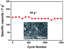
Polyoxometalates (POMs) based inorganic–organic composite materials have attracted considerable interest for energy storage and conversion applications. Modification of substrate materials is an effective method to achieve ideal electrochemical performance. Herein, poly(dimethyl diallyl ammonium chloride) (PDDA) functionalized graphene (PDDA–RGO) was used as the conductive matrix to support tungsten addenda mixed heteropolymolybdate, PMo12−xWxO403− (PMoW), with a facile, straightforward one-pot method. The cationic polyelectrolyte, PDDA, was employed as a linker to adsorb both RGO and POMs through electrostatic interactions. The resulting PMoW–PDDA–RGO composite exhibited a homogeneous honeycomb-like porous structure leading to fast ion transport and short ion diffusion pathways. In a typical two-electrode symmetric system, the supercapacitor exhibited a high rate specific capacitance of 140 F g−1 even at a high current density of 10 A g−1 and an energy density of 6.15 W h kg−1 at a power density of 250 W kg−1. After 1700 cycles at a fast discharge speed of 5 A g−1, the capacitance remained 94.6% of its initial capacitance.


Introduction

Supercapacitors (SCs), also called electrochemical capacitors or ultracapacitors, have occupied a special niche in energy storage systems because of their high power capability, long cycle stability, and relatively low cost.1–3 Distinct from conventional electrostatic capacitors that store charges on a thin layer of dielectric materials in an electric field, SCs store charges at the electrochemical interface between the electrode material and the electrolyte.4 According to the energy storage mechanism, SCs are classified into two types: (1) electrochemical double-layer capacitors (EDLCs), which have a high capacitance through charge accumulation at the electrode–electrolyte interface.5 (2) Pseudocapacitors, which possess Faraday capacitance through reversible redox reactions at the interface of electroactive materials and electrolyte.6 However, each type of capacitor has its own weaknesses. EDLCs with carbon-based materials usually suffer from a low energy density, whereas pseudocapacitors with transition metal oxides or hydroxides are impeded by their low electrical conductivity and low power density.7 An effective approach to solve these problems is to fabricate hybrid materials that can exert the synergistic effects between capacitive and faradaic properties.8 A series of hybrid materials have been reported, which are composed of carbonaceous materials, such as activated carbon (AC), carbon nanotubes (CNTs) and reduced graphene oxide (RGO), and transition metal oxides and hydroxides, such as MnO2, Co3O4, NiO, Fe3O4, V2O5 or Ni(OH)2, as well as polyoxometalates (POMs).8–11

Among various redox-active materials, POMs have been gradually identified as a promising candidate of electrode materials for energy storage systems due to their fascinating molecular and electronic structures, chemical tunability and rich redox properties.11–13 However, unfavorable natures of POMs include poor electronic conductivity and partial degradation in aqueous media.14–16 To overcome these problems, researchers are trying to design hybrid materials consisting of pseudocapacitive POMs and conductive substrates such as conducting organic polymers17,18 and carbon materials.19,20 Such types of hybrid materials may sufficiently utilize the unique chemical reactivity of POMs and the electronic properties of conductive substrates.

To date, the classical Keggin-type POM, 12-molybdophosphoric acid (PMo12), has been doped in the conductive polymer polypyrrole (PPy), and the PMo12/PPy hybrid shows a specific capacitance of 130 F g−1 at scan rate of 1 mV s−1.21 Another example of a hybrid material is PMo12/CNTs with a specific capacitance of 40 F g−1 and an energy density on a level of 1.3 W h kg−1.22 Gomez-Romero and co-workers anchored PMo12 to AC, which provided a specific capacity of 160 F g−1 at a current density of 2 A g−1.23 Subsequently, the same group synthesized a PMo12 and RGO nanomaterial (PMo12/RGO) via hydrothermal reactions with a specific capacitance of 123 F g−1 at a current density of 1 A g−1.24 Moreover, they used another classical Keggin-type POM, 12-phosphotungstic acid (PW12), for preparing a PW12/AC composite by ultrasonic processing with a specific capacitance of 254 F g−1 at 10 mV s−1 in a 3-electrode configuration and an extended voltage range up to 1.6 V in an acidic aqueous electrolyte.25

Moreover, the Keggin-type POMs with dual addenda metal elements, such as Mo/W and Mo/V mixed POMs, have been used in combination with multi walled carbon nanotubes (MWCNTs) for electrochemical capacitors (EC).26–29

In view of these basic research, we designed a new hybrid system in which three functional constituents were included: (1) tungsten addenda mixed heteropolymolybdates PMo12−xWx (denoted as PMoW) that are expected to obtain a more ideal rectangular capacitive profile with a synergistic effect between the Mo and W addenda atoms. (2) Reduced graphene oxide (RGO) that has an excellent conductivity and has shown the greatest potential for the development of electrodes with a high power density.30,31 (3) Poly(dimethyl-diallyl ammonium chloride) (PDDA) that is used to change the surface of RGO from negatively charged to positively charged, thus reinforcing the integration between the PMoW and the RGO.32,33 In this study, we explore a one-step hydrothermal method34,35 to prepare the three-component material, and the PMoW–PDDA–RGO ternary composite shows a honeycomb-like porous structure. Through combination of the rich electrochemical redox properties of PMoW, the effective connection of PDDA and the good electrical conductivity of RGO, the degradation of PMoW is avoided and remarkable supercapacitive performances with a high specific capacitance, good rate capacity and cycle stability have been obtained from the PMoW–PDDA–RGO composite in an acidic aqueous electrolyte (1 M H2SO4).

Experimental

Synthesis of active materials

All the reagents and solvents were of chemical pure grade and used as obtained. A PMoW solution was prepared according to the literature.28,29 Graphene oxide (GO) was obtained from the oxidation of graphite powder by the improved Hummers' method.36 The PMoW–PDDA–RGO composite was in situ fabricated through hydrothermal reactions (shown in Scheme 1): first, 0.3 mL of PDDA solution was dropped into a GO aqueous dispersion (2.0 mg mL−1, 15 mL) under vigorously stirring. When the mixed solution became homogeneous, 10 mL of PMoW solution (20 mmol L−1) was added, and the solution was continuously stirred for 1 h, then transferred into a Teflon-lined autoclave (50 mL) and heat-treated at 180 °C for 5 h. After cooling to room temperature, black floating solids were obtained by filtering with a membrane (pore diameter, 0.22 μm), then washed with deionized water and absolute ethyl alcohol, and then finally dried in a vacuum oven at 60 °C overnight. The PMoW–RGO composite and RGO were also prepared under the same conditions for control experiments.
image file: c6ra15381j-s1.tif
Scheme 1 Schematic preparation process of the PMoW–PDDA–RGO composite.

Materials characterization

The Fourier transform infrared spectra (FT-IR) were obtained by an infrared spectrometer (Nicolet 6700-FTIR, Thermo-Scientific). Powder X-ray diffraction (XRD) data of the materials were collected by a Rigaku P/max 2200VPC diffractometer with Cu Kα radiation. The 31P NMR spectra were obtained on a Bruker AV-400 spectrometer, referenced with 85% phosphoric acid. The amount of POMs in the composite was evaluated by thermo-gravimetric analysis (TGA, Pyris Diamond TG/DTA, PerkinElmer) from room temperature to 700 °C in air at a heating rate of 10 °C min−1. The Raman spectrum was obtained on a Raman spectrometer (JY HR-800, HORIBA JOBIN YVON) with an excitation laser beam wavelength of 488 nm to analyse the structural features of the samples. X-ray photoelectron spectra (XPS) were acquired using a VG ESCALABMKII spectrometer (VG Scientific Ltd., UK). The morphology was checked by a field-emission scanning electron microscope (FE-SEM, XL 30 ESEM-FEG, FEI Company) and a transmission electron microscope (TEM, JEM-2010F). To confirm the existence of mesopores in the composite, a nitrogen adsorption isotherm was carried out at −196 °C using a Micromeritics ASAP 2020 analyzer.

Electrochemical measurement

All electrochemical measurements were carried out using a CHI6082E electrochemical workstation. Working electrodes were obtained by mixing active materials (PMoW, PDDA, RGO or PMoW–PDDA–RGO) (75 wt%), acetylene black (15 wt%) and polyvinylidene fluoride (PVDF) (10 wt%) in N-methyl-pyrrolidinone (NMP) solvent. The as-prepared slurry was coated onto a pre-treated stainless steel foil and dried at 80 °C for 12 h in a vacuum oven. The average mass loading of the electrodes was about 1.4 mg cm−2. In a three electrode system, the composite electrode, Pt foil, and the saturated calomel electrode (SCE) were used as the working electrode, counter electrode and reference electrode, respectively. A 1 M H2SO4 aqueous solution was used as the working electrolyte. Cyclic voltammetry (CV) and galvanostatic charge/discharge measurements (GCD) were carried out in the potential range of −0.2 to +0.8 V. Symmetric supercapacitors were assembled using the PMoW–PDDA–RGO composite as both the positive and negative electrodes and tested in a two-electrode system between 0 and 1 V. The electrochemical impedance spectroscopy measurements (EIS) were performed over a frequency range from 105 to 10−2 Hz at an amplitude of 10 mV.

Results and discussion

Characterization of the POMs

During the preparation process of the PMoW–PDDA–RGO composite, H3PMo12O40 (PMo12) and H3PW12O40 (PW12) were used as POM precursors. The results of FT-IR, XRD, and 31P NMR measurements show that the POMs in the PMoW–PDDA–RGO composite are a mixture of H3PMo12−xWxO40 (denoted as PMoW), and the main species are H3PMo9W3O40 and H3PMo8W4O40 (details see Fig. S1, ESI).

Characterization of the PMoW–PDDA–RGO composite

The FT-IR spectra of GO, RGO, PMoW and PMoW–PDDA–RGO composite are shown in Fig. 1a. The characteristic vibrations, νas(C–O–C in epoxide) at 1080 cm−1, νas(C–O) at 1386 cm−1 and νas(C[double bond, length as m-dash]O) at 1640 cm−1, are observed in GO. However, these vibrations almost disappear in RGO, indicating that most of the oxygen-containing components have been removed from GO in the hydrothermal process. The vibration bands located at 1068 and 968 cm−1 are attributed to the νas(P–O) and νas(M[double bond, length as m-dash]O) (M = Mo/W) characteristic peaks, respectively. Peaks located at 875 and 791 cm−1 are attributed to the νas(M–O–M) (M = Mo/W) in PMoW, which verifies the retention of the Keggin-type PMoW in the as-prepared PMoW–PDDA–RGO composite.
image file: c6ra15381j-f1.tif
Fig. 1 (a) The FT-IR spectra and (b) TGA curves (in air) of PMoW, GO, RGO, and the PMoW–PDDA–RGO composite.

The content of PMoW in the composite is calculated to be 36.2 wt% on the basis of the TGA results (Fig. 1b). It is noted that the weight loss started at about 200 °C for GO, but at about 400 °C for both RGO and the PMoW–PDDA–RGO composite. This fact also supports the effective removal of oxygen-containing functional groups from GO.

Fig. 2a shows the X-ray diffraction (XRD) patterns obtained from GO, RGO, PMoW and PMoW–PDDA–RGO composite. The typical diffraction peak at about 10° for GO disappears for RGO, which evidences again the effective reduction of GO. Moreover, the typical peaks of the pristine PMoW become very flat for the PMoW–PDDA–RGO composite, which further demonstrates that the PMoW molecules are homogeneously dispersed in the composite.


image file: c6ra15381j-f2.tif
Fig. 2 (a) The XRD patterns of GO, RGO, PMoW and PMoW–PDDA–RGO composite. (b) The Raman spectra of GO, RGO and PMoW–PDDA–RGO composite.

The structural and electronic properties of the PMoW–PDDA–RGO composite are further explicated by Raman spectroscopy. As shown in Fig. 2b, two remarkable peaks located at around 1355 and 1600 cm−1 are observed in each Raman spectra, corresponding to the D band (associated with structural defects) and the G band (for the stretching vibration of sp2 carbon), respectively. The intensity ratios of the two bands (ID/IG) are 0.82 for GO, 0.90 for RGO and 0.98 for PMoW–PDDA–RGO. The value of ID/IG represents the electronic conjugation state of a carbonaceous material, and an increase in the value of ID/IG from GO to PMoW–PDDA–RGO implies that more defects and wrinkles have been generated.

XPS of GO, RGO and the PMoW–PDDA–RGO composite are shown in Fig. S2 (ESI). In the XPS of the PMoW–PDDA–RGO composite, the signals of C, O, N, Mo and W further prove the successful combination of PMoW and PDDA–RGO. Deconvolutions of the C 1s spectra also reveal the effective reduction of GO (Fig. 3). The relative signals of C–O (286.5 eV) and O–C[double bond, length as m-dash]O (288.8 eV) obtained from RGO and the PMoW–PDDA–RGO composite are obviously weaker than those obtained from GO, which confirm again that most of the epoxide, hydroxyl, and carboxyl functional groups have been removed. These results are consistent with the results of IR, XRD and TGA.


image file: c6ra15381j-f3.tif
Fig. 3 XPS spectra of C 1s obtained from (a) GO, (b) RGO and (c) the PMoW–PDDA–RGO composite.

Morphology analysis for the PMoW–PDDA–RGO composite has been done by SEM and TEM measurements, as well as for the PMoW–RGO composite as a comparison. The SEM image of the PMoW–PDDA–RGO composite presents a honeycomb-like interconnected network (Fig. 4a), which provides a larger electrolyte-penetration surface and interpenetrating channels for fast electron and ion transports.37 The TEM image further verifies the homogeneous interconnected mesoporous architecture present in the PMoW–PDDA–RGO composite (Fig. 4c). The HRTEM image obtained from a slice of the PMoW–PDDA–RGO composite shows consecutive lattice fringes of PMoW arrays, which explicates that PMoW molecules are discretely and uniformly dispersed in the PDDA–RGO sheets (inset in Fig. 4c). Fig. S3 (ESI) shows the N2 adsorption/desorption isotherm and the pore-size distribution of the PMoW–PDDA–RGO composite. The BET surface area of the PMoW–PDDA–RGO composite is 143.7 m2 g−1 and an average pore size of about 2.6 nm is calculated by the Barrett–Joyner–Halenda (BJH) method. The PMoW–RGO composite obviously shows a state of aggregation (Fig. 4b and d). This phenomenon may result from two aspects. On the one hand, the binding force between the PMoW and the RGO components will be weak without the presence of PDDA. On the other hand, RGO sheets possess a tendency to aggregate in a strong acidic solution of POMs under hydrothermal conditions.38


image file: c6ra15381j-f4.tif
Fig. 4 SEM images of the (a) PMoW–PDDA–RGO and (b) PMoW–RGO composites. (c) TEM image of the PMoW–PDDA–RGO, (inset is HRTEM analysis of a slice of composite). (d) TEM image of the PMoW–RGO composite.

Electrochemical measurements

Fig. 5a shows the CV curves of PDDA, PMoW, RGO and PMoW–PDDA–RGO composite at a scan rate of 10 mV s−1. The current generated from the PDDA electrode is negligible; the PMoW electrode shows three redox peaks with a lower current response due to poor electrical conductivity. A typical rectangular-like curve for carbonaceous materials is exhibited for the RGO electrode. The PMoW–PDDA–RGO composite electrode displays higher current responses stemming from the redox reactions in PMoW with three pairs of well-defined redox peaks located at +0.37/+0.33 V for i/i′, +0.12/+0.10 V for ii/ii′ and −0.09/−0.12 V for iii/iii′, vs. SCE. These electron transfer processes can be attributed to three consecutive, reversible, two-electron redox reactions of MoVI/MoV centres:23
 
PMoVI12−xWxO403− + 2e + 2H+ ⇄ H2PMoV2MoVI10−xWxO403− (1)
 
H2PMoV2MoVI10−xWxO403− + 2e + 2H+ ⇄ H4PMoV4MoVI8−xWxO403− (2)
 
H4PMoV4MoVI8−xWxO403− + 2e + 2H+ ⇄ H6PMoV6MoVI6−xWxO403− (3)

image file: c6ra15381j-f5.tif
Fig. 5 (a) CV curves of PDDA, PMoW, RGO and the PMoW–PDDA–RGO composite at 10 mV s−1. (b) CV curves of the PMoW–PDDA–RGO composite at different scan rates ranged from 2 to 200 mV s−1. Inset is a plot of peak current vs. scan rate for the third oxidation process (iii/iii′). (c) GCD curves of RGO and the PMoW–PDDA–RGO composite at a current density of 1 A g−1. (d) Rate performances of RGO and the PMoW–PDDA–RGO composite calculated through discharge curves.

The redox reactions of WVI/WV centres, which occur below −0.2 V, out of the voltage window of the studied SCs, are ignored here (see Fig. S4, ESI).25,29,39 The CV results imply that the PMoW–PDDA–RGO composite electrode combines double-layer capacitance, mainly provided by the RGO, and pseudocapacitance, mainly provided by the PMoW.11

Fig. 5b presents the CV curves of the PMoW–PDDA–RGO composite at various scan rates ranging from 2 to 200 mV s−1. It is observed that with an increase in the scan rates, the current densities are gradually enhanced and the three pairs of redox peaks are still well-defined, indicating a good rate capability. In addition, the peak currents increase linearly with the increased scan rate (Fig. 5b, inset), suggesting that the redox-process is surface-confined.25,32

Fig. 5c gives the GCD curves at a current density of 1 A g−1. The GCD of the PMoW–PDDA–RGO composite is not as smooth as that obtained from RGO, and the ripples just correspond to the redox waves in the CV. Calculated from the discharge curves, the specific capacitances are 223.7 F g−1 for RGO and 279.1 F g−1 for the PMoW–PDDA–RGO composite. The enhancement in the specific capacitance of the PMoW–PDDA–RGO composite can be attributed to a synergistic effect between the unique conductivity of the RGO and the rich electrochemical properties of the PMoW, as well as the effective connection between the RGO and PMoW by PDDA. In addition, factors such as the obtained homogeneous honeycomb-like porous structure leading to fast ion transport and short ion diffusion pathways, uniform dispersion of pseudocapacitive PMoW and inhibition of the degradation of PMoW, are also beneficial for the super capacitance.

To further evaluate the electrochemical rate performances of the as-prepared electrode material, specific capacitances were measured at different current densities (Fig. 5d). The specific capacitance of the PMoW–PDDA–RGO composite electrode was 253.6 F g−1 at a current density of 2 A g−1 and retained 224 F g−1 at a current density of 20 A g−1. While the RGO electrode displayed a laggard behaviour with 216.4 F g−1 at a current density of 2 A g−1 and 186 F g−1 at a current density of 20 A g−1.

In order to realize a practical application for the PMoW–PDDA–RGO composite in SCs, a symmetric SC device was assembled in a 2-electrode system. The GCD curves were recorded at a current density of 10 A g−1 in the potential range of 0–1 V in a 1 M H2SO4 aqueous solution (Fig. 6a). Fig. 6a clearly shows a longer discharge time for the PMoW–PDDA–RGO, implying a larger specific capacitance than that of RGO. Fig. 6b shows the GCD curves at various current densities from 1 to 20 A g−1 and the corresponding calculated rate performances are displayed in Fig. 6c. The PMoW–PDDA–RGO-based SC demonstrates a maximum specific capacitance of 177, 165.6, 151, 140 and 124 F g−1 at current densities of 1, 2, 5, 10 and 20 A g−1, respectively, which are superior to the previously reported results in the examples of Cs–PMo12/CNT (20 F g−1 at 2 A g−1),40 PMo12/CNTs (40 F g−1 at 1 A g−1),22 and PMo12/RGO (123 F g−1 at 1 A g−1).24 Cyclability is also a crucial factor for SCs. Fig. 6d exhibits an excellent cycling stability with retention of 94.6% of its initial capacitance after 1700 cycles at a high current density of 5 A g−1. The good electrochemical capability of the PMoW–PDDA–RGO composite predicts a possibility for practical SC application.


image file: c6ra15381j-f6.tif
Fig. 6 Electrochemical performances of the symmetric SCs. (a) GCD profiles of RGO and the PMoW–PDDA–RGO composite at 10 A g−1. (b) GCD profiles of the PMoW–PDDA–RGO composite at different current densities of 1, 2, 5, 10 and 20 A g−1. (c) Rate performances of RGO and the PMoW–PDDA–RGO composite calculated according to the discharge curves. (d) Cycling performance for the PMoW–PDDA–RGO composite SC at a current density of 5 A g−1.

An EIS test (Fig. 7) was employed to further study the charge transfer process at electrode/electrolyte interfaces. The equivalent series resistance (from the x-intercept of the Nyquist plot) of the PMoW–PDDA–RGO composite is 1.67 Ω and that of RGO is 2.07 Ω. The smaller value for the former implies much better ion diffusion and a lower contact resistance for the PMoW–PDDA–RGO composite. This is benefited from the 3D porous interconnected network of the PMoW–PDDA–RGO composite.


image file: c6ra15381j-f7.tif
Fig. 7 Nyquist impedance plots of RGO and the PMoW–PDDA–RGO symmetric SC.

In the two-electrode setup, the gravimetric specific energy density (E) and power density (P) of the symmetrical SCs are calculated based on the GCD curves from the following equations:

 
E = Csp × ΔV2/4 × (2 × 3.6) (4)
 
P = E × 3600/t (5)
where Csp is a gravimetric specific capacitance, ΔV is a cell voltage, and t is the discharge time in the GCD curves.

The specific energy density of the PMoW–PDDA–RGO symmetric SC is 6.15 W h kg−1 with a power density of 250 W kg−1 and retains 4.31 W h kg−1 with a high power density of 5 kW kg−1. The symmetric supercapacitor device developed in this work exhibits improved performances compared to most of the PMo12-based symmetric supercapacitors previously reported, including PMo12/polypyrrole//PMo12/polypyrrole (1.44 W h kg−1 at 18.9 W kg−1),41 PMo12/CNTs//PMo12/CNTs (1.3 W h kg−1 at 50 W kg−1),22 and PMo12/RGO//PMo12/RGO (4.3 W h kg−1 at 250 W kg−1).24

Conclusions

A new-type 3D-interconnected porous PMoW–PDDA–RGO composite has been facilely prepared by a one-pot hydrothermal method, and applied as an electrode material in acidic aqueous media for the first time. The PMoW–PDDA–RGO composite achieves a high specific capacitance, remarkable rate capability and good long-term stability, which are benefited from the cross-linked porous network, unique conductivity of RGO, and uniformly dispersed pseudocapacitive of the PMoW. Moreover, the PMoW–PDDA–RGO symmetric SC shows a high energy density of 6.15 W h kg−1 and a good cycling stability. It proves that POM-based RGO nanohybrids are a suitable candidate for high energy-density SCs.

Acknowledgements

This study was financially supported by the research grants from the National Natural Science Foundation of China (21373044).

Notes and references

  1. J. R. Miller and P. Simon, Science, 2008, 321, 651–652 CrossRef CAS PubMed.
  2. Y. Zhu, S. Murali, M. D. Stoller, K. J. Ganesh, W. Cai, P. J. Ferreira, A. Pirkle, R. M. Wallace, K. A. Cychosz, M. Thommes, D. Su, E. A. Stach and R. S. Ruoff, Science, 2011, 332, 1537–1541 CrossRef CAS PubMed.
  3. P. Simon, Y. Gogotsi and B. Dunn, Science, 2014, 343, 1210–1211 CrossRef CAS PubMed.
  4. G. Yu, X. Xie, L. Pan, Z. Bao and Y. Cui, Nano Energy, 2013, 2, 213–234 CrossRef CAS.
  5. Y. Zhai, Y. Dou, D. Zhao, P. F. Fulvio, R. T. Mayes and S. Dai, Adv. Mater., 2011, 23, 4828–4850 CrossRef CAS PubMed.
  6. L. Feng, Y. Zhu, H. Ding and C. Ni, J. Power Sources, 2014, 267, 430–444 CrossRef CAS.
  7. B. P. Bastakoti, H. Oveisi, C.-C. Hu, K. C. W. Wu, N. Suzuki, K. Takai, Y. Kamachi, M. Imura and Y. Yamauchi, Eur. J. Inorg. Chem., 2013, 2013, 1109–1112 CrossRef CAS.
  8. D. P. Dubal, O. Ayyad, V. Ruiz and P. Gomez-Romero, Chem. Soc. Rev., 2015, 44, 1777–1790 RSC.
  9. Q. Cheng, J. Tang, J. Ma, H. Zhang, N. Shinya and L.-C. Qin, Carbon, 2011, 49, 2917–2925 CrossRef CAS.
  10. L.-L. Zhang, H.-H. Li, C.-Y. Fan, K. Wang, X.-L. Wu, H.-Z. Sun and J.-P. Zhang, J. Mater. Chem. A, 2015, 3, 19077–19084 CAS.
  11. H. Y. Chen, R. Al-Oweini, J. Friedl, C. Y. Lee, L. Li, U. Kortz, U. Stimming and M. Srinivasan, Nanoscale, 2015, 7, 7934–7941 RSC.
  12. M. Genovese and K. Lian, Curr. Opin. Solid State Mater. Sci., 2015, 19, 126–137 CrossRef CAS.
  13. Y. Ji, L. Huang, J. Hu, C. Streb and Y.-F. Song, Energy Environ. Sci., 2015, 8, 776–789 CAS.
  14. Y. Kim and S. Shanmugam, ACS Appl. Mater. Interfaces, 2013, 5, 12197–12204 CAS.
  15. J.-P. Tessonnier, S. Goubert-Renaudin, S. Alia, Y. Yan and M. A. Barteau, Langmuir, 2013, 29, 393–402 CrossRef CAS PubMed.
  16. W. Zhang, D. Du, D. Gunaratne, R. Colby, Y. Lin and J. Laskin, Electroanalysis, 2014, 26, 178–183 CrossRef CAS.
  17. A. K. Cuentas-Gallegos, M. Lira-Cantú, N. Casañ-Pastor and P. Gómez-Romero, Adv. Funct. Mater., 2005, 15, 1125–1133 CrossRef CAS.
  18. G. M. Suppes, B. A. Deore and M. S. Freund, Langmuir, 2008, 24, 1064–1069 CrossRef CAS PubMed.
  19. T. Akter, K. Hu and K. Lian, Electrochim. Acta, 2011, 56, 4966–4971 CrossRef CAS.
  20. S. Park, K. Lian and Y. Gogotsi, J. Electrochem. Soc., 2009, 156, A921 CrossRef CAS.
  21. A. M. White and R. C. T. Slade, Electrochim. Acta, 2003, 48, 2583–2588 CrossRef CAS.
  22. M. Skunik, M. Chojak, I. A. Rutkowska and P. J. Kulesza, Electrochim. Acta, 2008, 53, 3862–3869 CrossRef CAS.
  23. V. Ruiz, J. Suárez-Guevara and P. Gomez-Romero, Electrochem. Commun., 2012, 24, 35–38 CrossRef CAS.
  24. J. Suarez-Guevara, V. Ruiz and P. Gomez-Romero, Phys. Chem. Chem. Phys., 2014, 16, 20411–20414 RSC.
  25. J. Suárez-Guevara, V. Ruiz and P. Gomez-Romero, J. Mater. Chem. A, 2014, 2, 1014–1021 Search PubMed.
  26. M. Genovese, Y. W. Foong and K. Lian, Electrochim. Acta, 2016, 199, 261–269 CrossRef CAS.
  27. G. Bajwa, M. Genovese and K. Lian, ECS J. Solid State Sci. Technol., 2013, 2, M3046–M3050 CrossRef CAS.
  28. M. Genovese and K. Lian, Electrochem. Commun., 2014, 43, 60–62 CrossRef CAS.
  29. M. Genovese, Y. W. Foong and K. Lian, J. Electrochem. Soc., 2015, 162, A5041–A5046 CrossRef CAS.
  30. V. Singh, D. Joung, L. Zhai, S. Das, S. I. Khondaker and S. Seal, Prog. Mater. Sci., 2011, 56, 1178–1271 CrossRef CAS.
  31. M. F. El-Kady, Y. Shao and R. B. Kaner, Nat. Rev. Mater., 2016, 1, 16033 CrossRef.
  32. M. Yang, B. G. Choi, S. C. Jung, Y.-K. Han, Y. S. Huh and S. B. Lee, Adv. Funct. Mater., 2014, 24, 7301–7309 CrossRef CAS.
  33. D. Bin, F. Ren, Y. Wang, C. Zhai, C. Wang, J. Guo, P. Yang and Y. Du, Chem.–Asian J., 2015, 10, 667–673 CrossRef CAS PubMed.
  34. N. Li, M. Cao and C. Hu, Nanoscale, 2012, 4, 6205–6218 RSC.
  35. J. Zhu, D. Yang, Z. Yin, Q. Yan and H. Zhang, Small, 2014, 10, 3480–3498 CrossRef CAS PubMed.
  36. D. C. Marcano, D. V. Kosynkin, J. M. Berlin, A. Sinitskii, Z. Sun, A. Slesarev, L. B. Alemany, W. Lu and J. M. Tour, ACS Nano, 2010, 4, 4806–4814 CrossRef CAS PubMed.
  37. T. Wang, L. Wang, D. Wu, W. Xia, H. Zhao and D. Jia, J. Mater. Chem. A, 2014, 2, 8352 CAS.
  38. Y. Zhou, Q. Bao, L. A. L. Tang, Y. Zhong and K. P. Loh, Chem. Mater., 2009, 21, 2950–2956 CrossRef CAS.
  39. M. Sadakane and E. Steckhan, Chem. Rev., 1998, 98, 219–238 CrossRef CAS PubMed.
  40. A. K. Cuentas-Gallegos, R. Martínez-Rosales, M. Baibarac, P. Gómez-Romero and M. E. Rincón, Electrochem. Commun., 2007, 9, 2088–2092 CrossRef CAS.
  41. A. M. White and R. C. T. Slade, Synth. Met., 2003, 139, 123–131 CrossRef CAS.

Footnote

Electronic supplementary information (ESI) available: FT-IR spectrum, XRD, and 31P NMR analyses of PMo12, PW12 and PMoW. XPS of GO, RGO, and the PMoW–PDDA–RGO composite. N2 adsorption–desorption isotherms and pore size distribution of the PMoW–PDDA–RGO composite. CV curves of PMo12 and PW12 at 10 mV s−1. See DOI: 10.1039/c6ra15381j

This journal is © The Royal Society of Chemistry 2016
Click here to see how this site uses Cookies. View our privacy policy here.