
 Open Access Article
 This Open Access Article is licensed under a Creative Commons Attribution-Non Commercial 3.0 Unported Licence
A copper based catalyst for poly-urethane synthesis from discarded motherboard†
Soumitra Barman‡
a,
Bibudha Parasar‡a,
Pradip Kundua and
Soumyajit Roy*ab
aEco-Friendly Applied Materials Laboratory, Department of Chemical Sciences, New Campus, IISER-Kolkata, India. E-mail: s.roy@iiserkol.ac.in; Fax: +91 3325873020; Tel: +91 9007222901
bSchool of Chemistry and Materials Engineering, Changshu Institute of Technology, Changshu, P. R. China
First published on 4th August 2016
Abstract
By displaying thermoplastic, elastomeric and thermoset behavior depending on their chemical and morphological properties, polyurethanes have caught attention since 1937 when Bayer and his co-workers made them for the first time using the reaction of polyester diol and isocyanate. To produce a great range of versatility, various isocyanates can be used for making linear or cross-linked polyurethanes. Here we used IPDI as isocyanate and bamboo polyol as polyalcohol to prepare hard polyurethane and polyurethane foam. A cheap copper-based catalyst has been synthesized from discarded motherboard to replace the industrially used tin-based catalyst DBTDL [dibutyltin(IV) dilaurate] which is expensive and we found almost similar productivity compared to conventional catalyst DBTDL. By optimizing catalyst loading, time and temperature, a 97% yield was obtained with 1.8 mol% catalyst loading in 2 hours. A plausible mechanism has also been proposed.
Introduction
Over the past decades, polyurethane (PU) has gained immense importance in contemporary and futuristic materials science. Industrially PUs are made by the addition of di- or polyisocyanates to polyols and this has been nicely summarised in a recent review.1 PUs have become important as elastomers, thermoplastics, thermorigids, adhesives, coatings, sealants and fibers.2 Flexible and rigid polyurethane products can be obtained from simple precursors like toluene diisocyanate (TDI) and methylene diphenyl isocyanate (MDI). Thermoplastic elastomers and thermoset resins have great market value as they are used in the aeronautic industry.3 Hence the demand for PU catalysts has also increased steadily. On the other hand, discarded computer hardware poses an imminent environmental threat. Hard polyurethane catalysis needs a gelling catalyst whereas polyurethane foam catalysis requires both a gelling catalyst and a blowing catalyst serving different roles. A gelling catalyst favors the reaction between isocyanate and alcohol whereas a blowing catalyst facilitates the reaction between isocyanate and water. Moreover, the desired PU catalyst would also require cyclo-trimerization catalyst to harden the material, oxazolidone catalysts and carbodiimide catalysts to impart thermal resistant properties in addition to gelling and blowing actions.4 Although several tertiary amine catalyst5–7 have been used as blowing catalyst and several delayed action catalysts8 have been used to control reactivity profiles, they all have a problem. So, alternative catalysts have been used as blowing agents.9 Moreover non-emission catalysts such as tertiary amines with reactive groups such as –OH or –NH2 have also been used. Triethylenediamine based catalyst10 and commercially available amine N-substituted morpholine11 are often used to avoid fogging and odor problems. Even tertiary alkanolamine based catalysts are used for PU foam preparation.12 A dendrimeric catalyst based on methylated polypropylene imine has been developed to prepare odorless PU foam.13 Several other amine-based catalyst14–17 have also been developed. Moreover, commercially available compounds such as guanidine,18 thiourea,18 urea derivatives19,20 have also been explored in PU catalysis. Very recently Hedrick et al. have summarized the synthesis of polyurethane using organocatalysis.21,22 To tackle tackiness, an aminoimide23 based catalyst, which could give desirable tack-free times from components of polyols and polyisocyanates has been used. Some other catalysts such as quaternary hydroxyalkyl tertiary amine,24,25 aminoborate esters,26 aminioorthesters,27 diimines28 have also been developed. Green alternatives like ionic liquid-based catalyst with different cation components such as imidazolium,29,30 phosphonium,31 iminium,32 quaternarized borates and non-fugitive catalysts have also been used for the preparation of polyurethane.33–35 Although concerted efforts exist to phase out amine catalysts to rid the foam of fogging problem, little has been done to replace the traditional gelling catalyst DBTDL (dibutyltin(IV) dilaurate).36 For instance, acetylacetone complexes of different transition metals are chemically synthesized and used as catalyst. However several other compounds such as stannous 2-ethylhexanoate, stannous octanoate, dibutyltin 2-ethylhexanoate, dibutyltindiacetate, dioctyltin dimercaptide37 are used as gelling catalyst; they all have toxicity and price issues. Hence there is a need for an eco-friendly catalyst that is cheap, efficient and effective. We now describe the design of our catalyst.In recent years, copper has emerged as a versatile catalyst for diverse transformations and is abundant in computer motherboard.38–52 So, it is perhaps possible to design a catalyst with copper as the central metal atom, with oligomers stabilizing long chain as its counter ion. Copper is also easily extractable from discarded computer motherboard. Our intrinsic hypothesis is based on the assumption that, both the alcohol and isocyanate chelates the central metal atom copper in the first step. Subsequently, the activated alcoholic hydrogen then transfers its hydrogen to the isocyanate bonded to the copper in a fashion similar to the mechanism to that of DBTDL.53 The motherboard based copper complex finally releases the urethane molecule to regenerate the catalyst.
To test this hypothesis, copper is extracted from discarded computer motherboard. As mentioned earlier, this choice is prompted by the growing menace of discarded computer motherboard in enhanced heavy metal poisoning, especially in emerging economies. Toxic metal scrapes from computer hardware are sometimes manually scavenged or left unattended to enter into ecosystem causing severe environmental problems. Hence our choice to utilize different copper components of a discarded motherboard as a catalyst would address environmental pollution issues. Bamboo is chosen as the source of polyol. Commercially available IPDI is used as an isocyanate. Sodium dodecyl benzene sulfonate (DBSNa) is chosen as the surfactant counter ion for its interfacial steric and charge stabilizing agent for copper ion and can form stable colloidal complex. Using this motherboard based copper catalyst we have prepared hard polyurethane and polyurethane foam.
Experimental section
All the chemicals were of reagent grade quality purchased from commercially available sources and used without further purification. NMR was recorded in Bruker 500 MHz Spectrometer. The Fourier transform infrared (FTIR) spectra reported in this study are recorded as KBr pellets with a Nicolet 380 FT-IR spectrometer in the range 4000–500 cm−1. Optical images are taken by a Zeiss axiocam camera. SEM images are acquired by Hitachi table-top Microscope, Model No. TM3000. TEM images are taken by a Jeol JEM 2010 electron microscope operated at 300 kV. C, H, N, analysis was carried out using Perkin-Elmer 2400 series II CHNS/O series elemental analyzer. Gravimetric determination of Cu was carried out using standard procedure.54 EDAX with SEM was carried out for elemental mapping using Carl Zeiss SUPRA 55VP FESEM. The thermogravimetric analysis (TGA) was accomplished on a Mettler Toledo TGA/SDTA 851e instrument at a heating rate of 10 °C min−1 with a sample weight of 5 mg in nitrogen atmosphere.Preparation of Cu-based catalyst
0.4 g of copper-alloy is removed from a discarded motherboard and dissolved in 3 mL of concentrated HNO3 (the nitrogen dioxide produced during dissolution of Cu in conc. HNO3, is poisonous. So this reaction must be carried out in fume hood). A 0.095 M aqueous solution of sodium dodecylbenzene sulfonate (DBSNa) is prepared by dissolving 2 g of DBSNa in 60 mL of water. The copper solution is added dropwise to aqueous DBSNa with mild stirring. The so formed blue, turbid colloidal dispersion is allowed to settle for 10 minutes. The solid product is collected by filtration, washed with cold water and is dried at room temperature for 2 days prior to further use.Preparation of hard polyurethane
To a neat glass vial, 0.5 g of bamboo polyol (prepared according to a previously reported method55) and 0.5 g of IPDI is added and the mixture is stirred well for 2 minutes. 0.1 g of the above prepared Cu-based catalyst is weighed and dissolved in 1 mL of butyl acetate and mechanically mixed for 5 minutes till all the catalyst is solubilized. 300 μL of this solution is taken in a clean pipette and added to the reaction mixture. The solution is stirred well for 10 minutes at room temperature to allow them to mix. The reaction temperature is then gradually increased to 60 °C and the temperature is maintained for 2 hours. After the completion of the reaction, the hardened polyurethane is collected and washed with (acetic acid + water) mixture in a ratio of 1![[thin space (1/6-em)]](https://www.rsc.org/images/entities/char_2009.gif) :20. After washing three times, it is air-dried prior to any further characterization. The entire sequence of polyurethane preparation is summarized in Fig. 1.
:20. After washing three times, it is air-dried prior to any further characterization. The entire sequence of polyurethane preparation is summarized in Fig. 1.
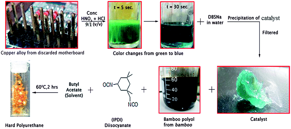 | ||
| Fig. 1 Sequential pathway for the preparation of polyurethane. | ||
Preparation of polyurethane foam
To a neat glass vial, 0.5 g of bamboo polyol and 0.5 g of IPDI is added and the mixture is stirred well for 2 minutes. 0.1 g of the above prepared Cu-based catalyst is weighed and dispersed in 1 mL of water and mechanically mixed for 5 minutes till it creates a uniform milky white dispersion. 300 μL of this solution is taken in a clean pipette and added to the reaction mixture. The solution is stirred vigorously for 30 minutes at room temperature. The foam is allowed to rise at room temperature. After that, the foam is cured at room temperature for 4 days. The polyurethane foam is collected and washed very slowly with (acetic acid + water) mixture in a ratio of 1:20. After washing three times, it is air-dried prior to any further characterization.
Results and discussion
Optimization of the Cu-based catalyst preparation
To prepare an effective Cu-based catalyst, it is important to first dissolve the motherboard based copper interfaces in a suitable liquefying medium. To do so, the interfaces are removed from the motherboard interfaces and are dissolved in concentrated acid medium. Concentrated acids of HCl, HNO3, H2SO4, CH3COOH and H3PO4 are screened as the solubilizing medium. In all the experiments 0.16 g of copper is dissolved in 1 mL of concentrated acid. Out of all the acids, only HNO3 is effective and dissolves the computer based motherboard interfaces in 30 seconds. In the process, the solution undergoes a transition in appearance from greenish yellow to light blue (Fig. 1). In HCl, the process is very slow as well in other acids. With the aim to reduce time further so as to reduce the total cost of polyurethane, two acid systems are screened. To our surprise, 10 vol% of HCl in HNO3 dissolves the copper in 10 seconds. Further reduction of time is attempted by increasing the volume percentage of HCl, but it takes longer time and the trend goes on increasing (Fig. 2).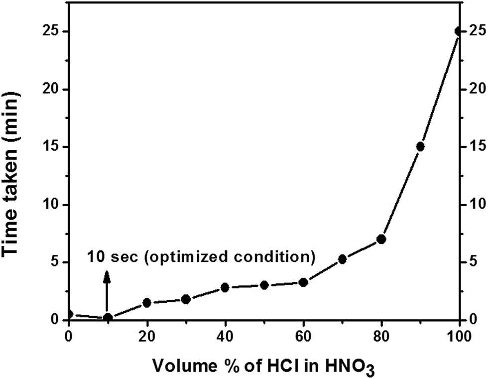 | ||
| Fig. 2 Dissolution of copper interfaces as a function of volume percentage of HCl in HNO3 with time. | ||
So, 10 vol% of HCl in HNO3 is chosen as the optimized solvent system for digesting copper from the motherboard of the catalyst. Owing to the change in color of the solution (from green to blue) and due to the existing oxidizing environment, it is reasonable to think that, copper is in cupric(II) state.
To further follow-up our working hypothesis, the prepared copper solution is added to a solution of anionic surfactant to get a copper catalyst with long charged hydrophobic chains as sterically stabilizing counter ions. Sodium dodecyl sulfate (SDS) is chosen as the starting point of our investigation; however it does not lead to compartmentalization. So, other anionic surfactant molecules such as sodium laurate, sodium palmate and sodium stearate are also tried. But they also fail to give any isolable solid product possibly because of lack of hydrophobicity.
However, initial turbidity observed. So, it is envisaged, use of a long hydrophobic chain with an aromatic ring may result in enhanced hydrophobicity, where the π–π stacking between two molecules direct the compartmentalization of the solvent system and helps in precipitation of the catalyst. Sodium salt of dodecylbenzenesulfonate (DBSNa) results in absolute compartmentalization of the biphasic system, which is subsequently filtered, air dried and used in reaction protocol optimization.
In summary, the Cu-based catalyst is finally prepared by adding the blue solution to a solution of DBSNa (sodium dodecylbenzene sulfonate) in water. The origin of turbidity is attributed to compartmentalization of the continuous solvent system (water) by the hydrophobic chains of DBS enveloping central Cu2+ ion core forming a sterically stabilized colloidal Cu2+ in water. More DBS is added to induce instability in the system and to precipitate the catalyst. The catalyst is then filtered off slowly as a blue oily solid-paste.
TEM and SEM characterization of Cu-based catalyst
Transmission electron microscope (TEM) and high-resolution TEM images of the catalysts were taken after drying in butyl acetate (Fig. 3A). TEM image shows agglomerated irregular network suggesting gel type morphology of the catalyst system. SEM-EDAX pattern ensures that Cu, S, C and O atoms are present in our catalyst (Fig. 3B). Highest peak in the EDX pattern indicates Si atom as it was taken on Si-wafer. The foam is characterized with optical stereo microscope. The substrate scope is also checked for foam with MDI.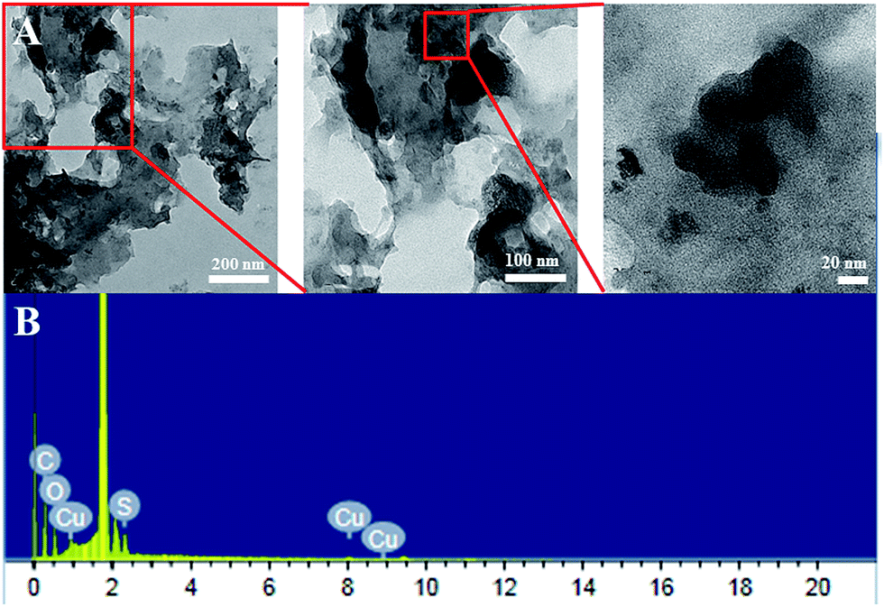 | ||
| Fig. 3 (A) Transmission electron microscopy images of the motherboard based copper catalyst. (B) SEM-EDAX pattern of Cu-based catalyst. | ||
The dark field optical stereo images are taken, which clearly shows the compactness of the material, which in turn implies at efficient formation of polyurethane (Fig. 4). SEM images also show similar morphology (Fig. 4).
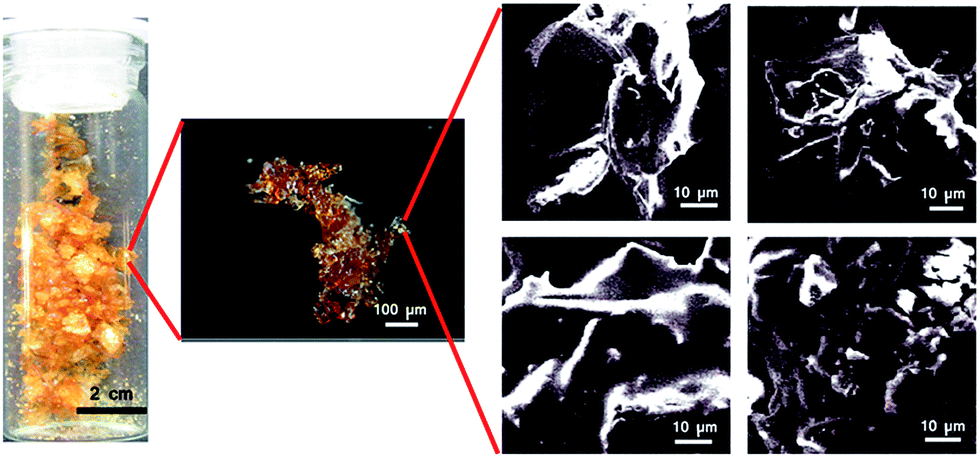 | ||
| Fig. 4 Dark field stereo pictures and SEM images of hard polyurethane with IPDI. | ||
Optical images of the polyurethane foam are also taken, which show pores with sizes ranging from 100 μm to 300 μm (Fig. 5).
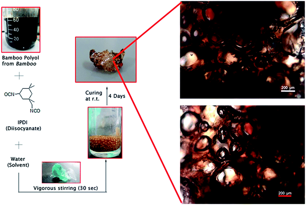 | ||
| Fig. 5 Synthetic scheme and optical stereo images of polyurethane foam. | ||
TGA analysis of Cu-based catalyst and DBSNa
TGA experiment was carried out with a heating rate of 10 °C min−1 under a nitrogen flow of 60 mL min−1. Temperature was increased from 30–700 °C. Each sample was weighted separately with 5 mg of sample. At 100 °C weight loss was found due to water loss (black). A sharp decrease at 480 °C indicates the loss of sulfate group in both cases (Fig. 6). The remaining residue is coming from infusible CuSO4 salt.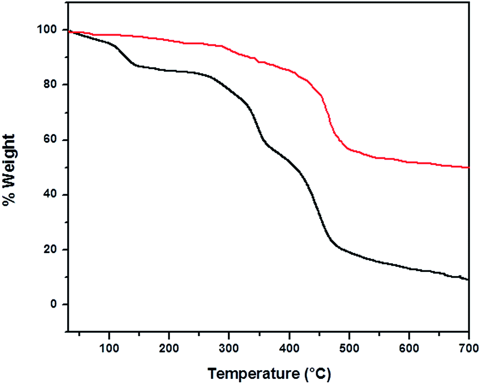 | ||
| Fig. 6 TGA curves of DBSNa (in red) and Cu-based catalyst (in black) at a heating rate of 10 °C min−1. | ||
Optimization of the reaction condition
Taking the hydroxyl value for crude glycerol as 991 mg KOH per g and that for PEG 400 as 268 mg KOH per g, hydroxyl value for the bamboo polyol comes out to be 186 mg KOH per g, which is very much close to the value reported previously by others.51 The model reaction between bamboo polyol and IPDI 1 in the presence of the discarded motherboard based catalyst is chosen as the starting point of our investigation (Table 1) (Scheme 1).| Entry | Catalyst (mol%) | Time (hour) | Temperature (°C) | % yield |
|---|---|---|---|---|
| 1 | 0.0 | 7 | 60 | 36 |
| 2 | 0.3 | 7 | 60 | 83 |
| 3 | 0.6 | 7 | 60 | 95 |
| 4 | 0.9 | 4.5 | 60 | 97 |
| 5 | 1.2 | 4 | 60 | 95 |
| 6 | 1.8 | 2 | 60 | 97 |
| 7 | 1.8 | 2 | 80 | 94 |
| 8 | 1.8 | 2 | 100 | 92 |
| 9 | 1.8 | 2 | 120 | 90 |
| 10 | 1.8 | 8 | 50 | 83 |
| 11 | 3.0 | 2 | 60 | 96 |
| 12 | 3.0 | 8 | 50 | 97 |
| 13 | 6.0 | 2 | 60 | 97 |
| 14 | 6.0 | 8 | 50 | 95 |
 | ||
| Scheme 1 Polyurethane from bamboo polyol and IPDI. | ||
For temperature dependent experiment we have used 1.8 mol% Cu-based catalyst. The reaction mixture is heated at 60 °C and after 7 hours a solid product is formed. The FTIR of the solid sample is compared with the DBTDL based polyurethane and FTIR spectra confirmed it to be polyurethane (see later). With the aim of further reducing the reaction time, subsequent optimization is done with the fine-tuning of the reaction parameters (Table 1, entry 2–14) (Fig. 7).
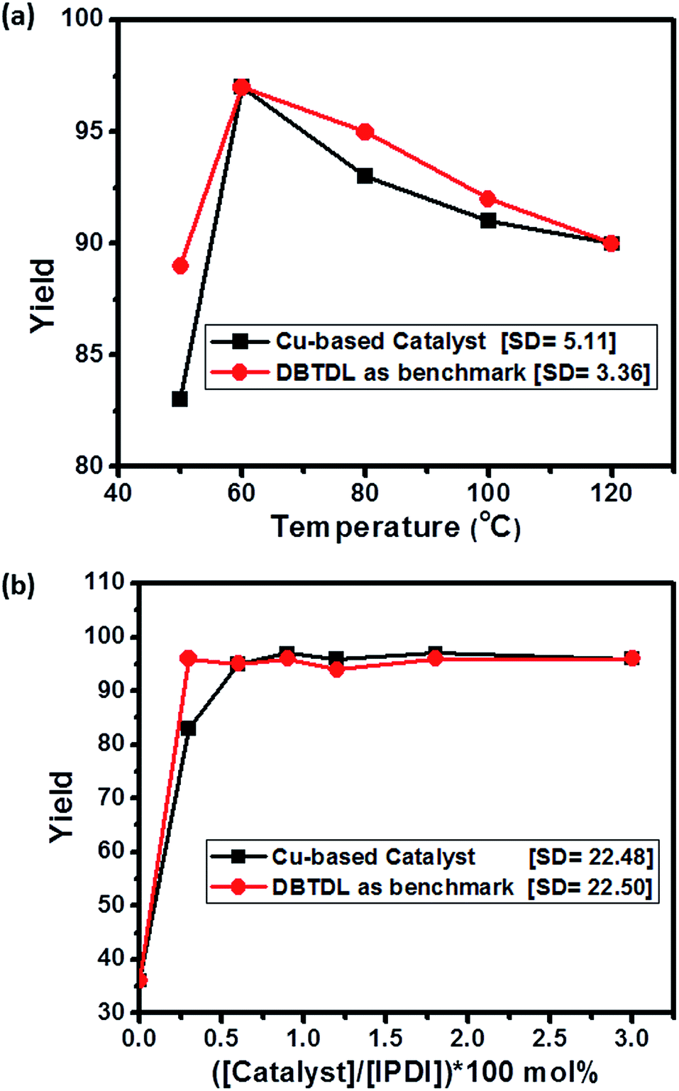 | ||
| Fig. 7 (a) Dependence of polyurethane yield with temperature. (b) Effect of catalyst loading on polyurethane yield. | ||
In the next attempt to maximize the yield with respect to the catalyst loading, an increase in yield is observed with an increase in catalyst loading as expected (Table 1, entry 1, 2, 9, 11) (Fig. 7b). At 0.9 mol% of catalyst loading, PU is afforded in quantitative yield. Our attempt to decrease the time required to complete the reaction with increasing the catalyst loading fail as it does not result in substantial decrease in reaction time. For instance, even at 6 mol% of catalyst loading, it takes two hours for the reaction to go to completion.
So, simultaneous optimization of the three axes (time, temperature and catalyst loading) finally leads to the optimized reaction protocol (Table 1, entry 6), which furnishes nearly full conversion of reactants to give the desired polyurethane.
Composition and nature of Cu-based catalyst
From C, H, N analysis we find the carbon content in our catalyst to be 22.06%, H = 3.98%. From gravimetric analysis we find Cu content in the catalyst to be 53.12%. Hence it follows that in the catalyst Cu/C ratio is 0.45. It further follows that in the catalyst Cu/DBSNa ratio is 0.28. Now we explain this composition from the measurement of zeta potential of the related colloidal catalyst in water by varying Cu/DBSNa ratio. As we decrease the Cu/DBSNa ratio from 2 to 1.6 and further, we see a charge inversion with concomitant induction of instability of the system (Fig. 8). In other words as the ratio of Cu/DBSNa decreases from 2 to 1.6 and lower, precipitation starts. Since our catalyst is precipitated by decreasing the Cu/DBSNa ratio hence it is expected that in the actual precipitated catalyst Cu/DBSNa ratio should be less than 1.6. Now we compare this system to the actual synthetic condition of our catalyst and we indeed note that the elemental analysis value of Cu/DBSNa for our precipitated catalyst is found to be 0.28 experimentally. Hence both the zeta potential analysis and elemental analysis converges and points towards a colloidal nature of the catalyst.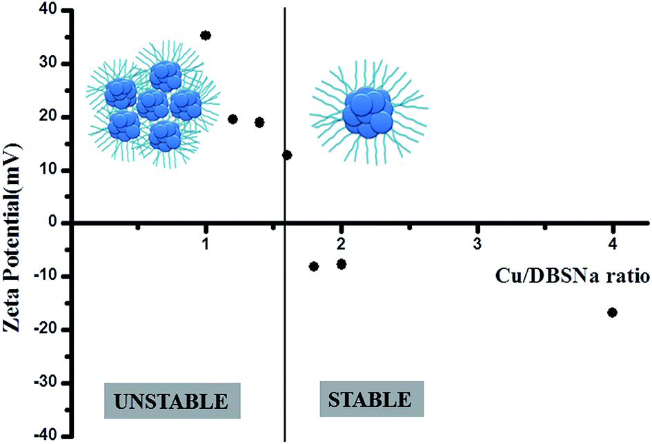 | ||
| Fig. 8 Plot of zeta potential with Cu/DBSNa concentration along with pictorial representation of the catalyst, showing Cu2+ ions in blue and strings represent DBS−. | ||
The convergence means, since we obtain our catalyst by precipitation, i.e., from the unstable regime of the colloidal system hence the Cu/DBSNa ratio in the precipitate should be less than 1.6. This is indeed observed to be the case with our elemental analysis value of the catalyst showing a Cu/DBSNa ratio of 0.28.
Hence it further follows that in the catalyst we have 3.6 DBSNa units for every Cu2+ ion (Fig. 8). Thus it means our catalyst is colloidal in nature where Cu2+ ion core is stabilized by DBSNa which becomes unstable in dispersion as more DBSNa is added during its synthesis. As the ratio of Cu:DBSNa reaches 1.6 and lesser with more DBSNa added the catalyst is precipitated. The precipitated catalyst has a Cu/DBSNa ratio of 0.28 and lies far left of the plot in Fig. 8 and is also the active catalyst.
Efficiency of Cu-based catalyst
The results from the prepared Cu-based catalyst are compared with respect to that of the conventional catalyst DBTDL. DBTDL is used as a benchmark catalyst here. It turns out, at 0.3 mol% loading of DBTDL, polyurethane is obtained in 95% yield, within 30 minutes (Fig. 7b), whereas 0.6 mol% of loading, catalyst affords 95% yield in 7 hours (Table 1, entry 3). The polyurethane so synthesized is characterized by FTIR, SEM and optical stereo microscope. The catalyst is tested for its substrate scope and its generality. When methylene diphenyl diisocyanate (MDI) is used, PU was obtained in 97% yield. Encouraged by our success in synthesizing polyurethane, it is checked if the motherboard based copper catalyst can catalyze the PU foam reaction at room temperature. It is worth noting that, at 0.6 mol% catalyst loading PU foam is obtained at nearly quantitative yield, thus proving its general applicability as a PU gelling catalyst.Model reaction & proposed reaction mechanism
However, open question remains: why does the motherboard based copper catalyst take 2 hours to complete the reaction even at 6 mol% catalyst loading, whereas a small amount of DBTDL can catalyze the reaction within 30 minutes? The results completely fit into our hypothesis.In the DBTDL based mechanism, in the last step, the laurate acts as the nucleophile and displaces the urethane product. On the contrary, in this copper based mechanism, there is no such nucleophile to displace urethane. So, the neutral molecule urethane undergoes ligand elimination to regenerate the catalyst, which is possibly a slow equilibrium process (Scheme 2). Looking at the optimization of the reaction condition, as we increase the loading of our Cu-based catalyst, yield of product increases. This is possibly because of higher diffusion rate of reactant through catalytic pore towards catalystic surface where reaction occurs. So we can tell this is a mass transfer limited reaction.56
 | ||
| Scheme 2 Proposed mechanism of polyurethane synthesis from bamboo polyol and IPDI with Cu-based catalyst. | ||
We modeled our reaction (Scheme 3) with IPDI and benzyl alcohol to investigate the role of Cu in the reaction. So we have done the reaction using Cu powder, DBSNa, and with Cu-based catalyst separately. In those reactions, with our catalyst, product was formed relatively faster than Cu powder as catalyst whereas no reaction was noticed with DBSNa as catalyst (Table S1†). So it is logical to say Cu is activating polyol by coordinating with oxygen atom of polyol. Current investigations are on the way to understand the mechanism in more detail.
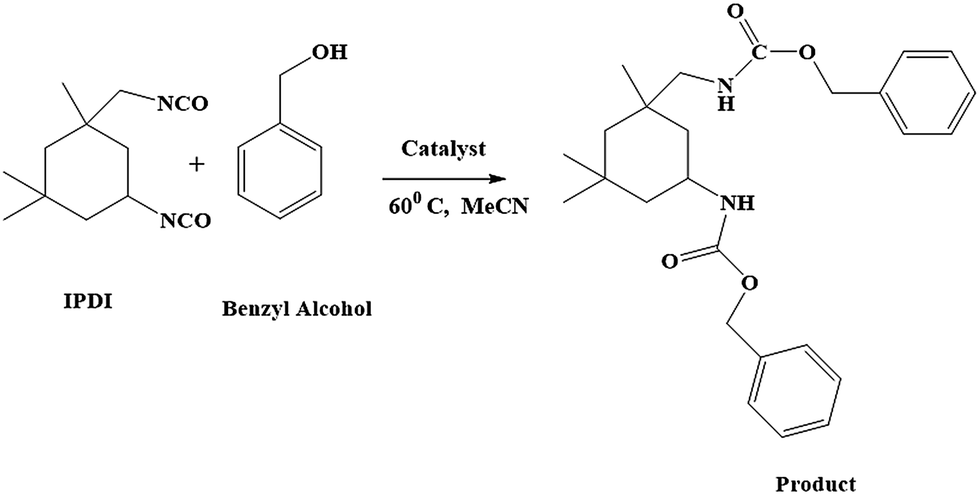 | ||
| Scheme 3 Model reaction of IPDI with benzyl alcohol using Cu-based catalyst. | ||
Spectroscopic characterization
Fourier transform infrared spectroscopy is employed to analyze the catalyst (Fig. 9). The catalyst exhibits the characteristics of the fundamental and the split ν3(S–O) bond vibration. The two prominent vibration of SO3, i.e. νas(SO3−) and νs(SO3−) are observed at 1192 cm−1 and 1041 cm−1 respectively, thus proving the existence of dodecylbenzene sulfonate as the counter ion for copper. The colloidal assembly of the copper and the DBS can be easily realized by comparing the stretches in the sulfonate region. The newly formed copper–oxygen bond decreases the electron density on oxygen, thereby inducing a slight red shift in the corresponding ν(SO3−) vibration frequency.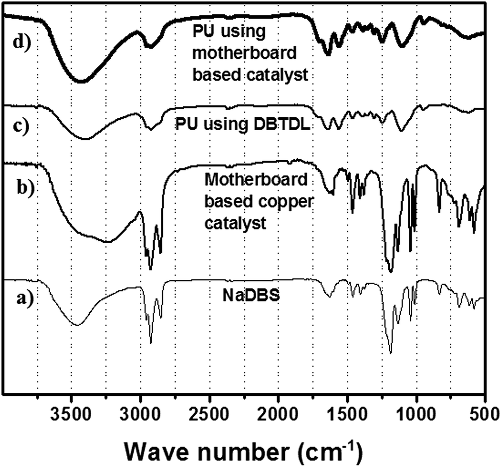 | ||
| Fig. 9 IR of (a) sodium dodecyl benzene sulfonate, (b) copper based catalyst, (c) polyurethane using DBTDL, (d) polyurethane using the copper-based catalyst. | ||
The peak at 3225 cm−1, on the other hand, is attributed to the hydrogen bonding between the proton and the sulfonic oxygen of two molecules, where the proton mediates the stacking of aromatic regions of catalyst. Such a situation is also reflected in peak broadening of the sulfonate region. However, we cannot rule out the possibility of self-stacking of free sulfonate ions on the surface of copper DBS–colloidal complex.
A typical FT-IR spectrum of the polyol–IPDI polyurethane prepared at the optimized condition is shown (Fig. 10a). The peak at the wave-number 3436 cm−1 is attributed to the stretching vibration of N–H: ν(NH). The peak at 2921 cm−1 is caused by the asymmetric stretching vibration of CH2 or νas(CH2). A distinct characteristic peak at 1640 cm−1 is attributed to the abundance of amide I bands, which clearly shows the formation of polyurethane.
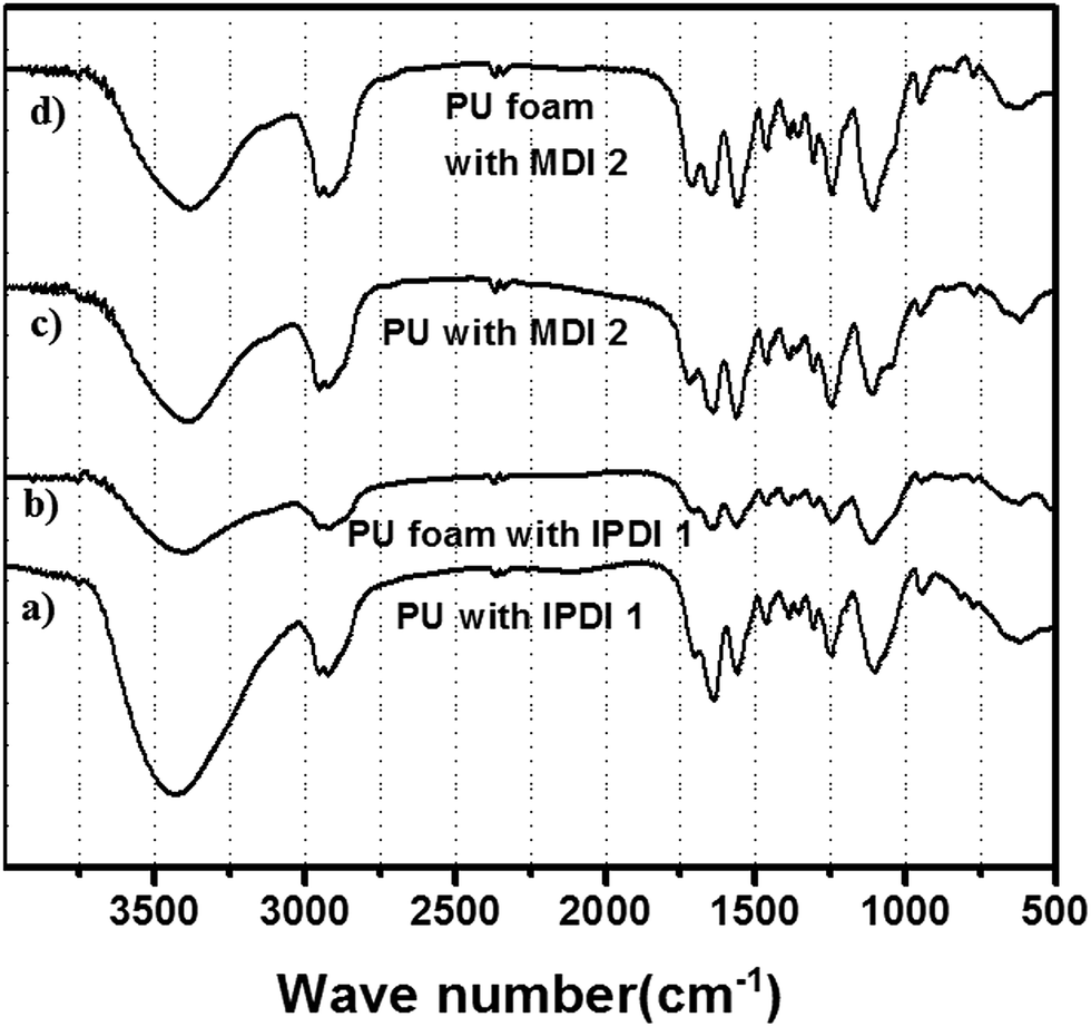 | ||
| Fig. 10 FT-IR spectrum of the (a) PU with IPDI 1, (b) PU foam with IPDI 1, (c) PU with MDI 2, (d) PU foam with MDI 2. | ||
A strong stretching C–O–C vibration at 1100 cm−1 proves the participation of both polyol and diisocyanate and hence corroborates the abundance of allophanates. The clear peaks at 1545 cm−1 is assigned to the amide band II [δ(N–H) + ν(C–N)]. Evidence of PU formation even comes from the vibration at 1230 cm−1, which is attributed to the amide III band [ν(C–N) + δ(N–H)]. The FTIR of PU foam also shows similar vibration frequency (Fig. 10).
Conclusions
In summary, we have developed a green protocol for the polyurethane reaction by a discarded motherboard based copper catalyst. The copper-based catalyst reported here is a colloidal assembly of Cu2+–DBS− which is precipitated by destabilizing a charge and steric-stabilized colloidal catalytic system by excess addition of DBSNa. The catalyst is non-toxic and does not require any synthetic modification and under the optimized condition with the three parameters (time, temperature and catalyst loading), it could promote the polyurethane reaction in nearly quantitative yield within 2 hour at 60 °C. Furthermore, synthesis of polyurethane foam proves the generality of the catalyst and it's potential to displace the currently used toxic and expensive catalysts. The next step would be in the direction of a complete green protocol for the synthesis of polyurethane with starting materials (di/polyol and di/polyisocyanate) being derived from a single environmentally friendly preferably a discarded resource. Such a discarded resource for PU catalyzed by a discarded motherboard catalyst would be the next step forward for a greener tomorrow.Acknowledgements
SR gratefully acknowledges the grants from IISER-Kolkata, India, DST-fast track, BRNS-DAE grant and CIT, P. R. China.References
- H. W. Engels, H. G. Pirkl, R. Albers, R. W. Albach, J. Krause, A. Hoffmann, H. Casselmann and J. Dormish, Angew. Chem., Int. Ed., 2013, 52, 9422–9441 CrossRef CAS PubMed.
- D. Dieterich and H. G. Schmelzer, Polyurethane Handbook, ed. G. Oertel, Hanser Publishers, Munich, 1994, p. 29 Search PubMed.
- E. Delebecq, J. P. Pascault, B. Boutevin and F. Ganachaud, Chem. Rev., 2013, 113, 80–118 CrossRef CAS PubMed.
- K. Ashida, Polyurethane and Related Foams: Chemistry and Technology, CRC Perss, Taylor & Francis Group, 2007 Search PubMed.
- M. Orchin, Houdry Process Corp., US Pat., US 2939851, 1960.
- S. Hashimoto, International Progress in Urethanes, 3, ed. K. Ashida and K. C. Frisch, Technomic, Lancaster, PA, 1981; p. 43 Search PubMed.
- H. H. Hubert and K. H. Gluzek, Proceedings of the FSK/SPI Polyurethane World Congress, Aachen, F.R. Germany, Septmember 29–October 2, 1987, p. 820 Search PubMed.
- F. M. N. Casati and F. W. Arbier, Proceedings of the SPI 27th Annual Technical/Marketing Conference, Bal Harbour, FL, October 20–22, 1982, p. 35 Search PubMed.
- D. Reed, Polyurethanes World Congr. 1997 Proc., 2000, 17, 22 Search PubMed.
- G. V. V. Cauwenberge, J. P. Melder, J. T. Anders, C. Benisch, R. Klopsch, G. Daun, C. Dully, B. Buschhaus, H. Boeckemeier and E. Pox, PCT Int. Appl., WO 2009030649 A2 20090312, 2009 Search PubMed.
- A. Strachota, B. Strachotova and M. Spirkova, Mater. Manuf. Processes, 2008, 23(6), 566–570 CrossRef CAS.
- J. J. Burdeniuc, Eur. Pat. Appl., EP 1457507 A2 20040915, 2004 Search PubMed.
- P. E. Froehling and T. Corstjens, Polym. Mater.: Sci. Eng., 1997, 77, 534–535 CAS.
- F. Jachimowicz, US Pat., US 4563484 A 19860107, 1986.
- F. Jachimowicz, US Pat., US 4450246 A 19840522, 1984.
- E. E. McEntire, Can. Pat., CA 1132292 A2 19820921, 1982.
- R. L. Zimmerman and E. E. McEntire, US Pat., US 4342687 A 19820803, 1982.
- H. Horacek, M. Barl, R. Wurmb and M. Marx, Ger. Offen., DE 3003963 A1 19810813, 1981 Search PubMed.
- R. L. Zimmerman, US Pat., US 4242467 A 19801230, 1980.
- R. L. Zimmerman, US Pat., US 4156760 A 19790529, 1979.
- H. Sardon, A. Pascual, D. Mecerreyes, D. Taton, H. Cramail and J. L. Hedrick, Macromolecules, 2015, 48, 3153–3165 CrossRef CAS.
- D. V. Palaskar, A. L. Boyer, E. Cloutet, C. Alfos and H. Cramail, Biomacromolecules, 2010, 11, 1202–1211 CrossRef CAS PubMed.
- E. E. McEntire, US Pat., US 4094827 A 19780613, 1978.
- I. S. Bechara, F. P. Carroll, R. L. Mascioli, and J. R. Panchak, U. S. Publ. Pat. Appl. B, US 497194 I5 19760203, 1976 Search PubMed.
- I. S. Bechara, F. P. Carroll and R. L. Mascioli, US Pat., US 3892687 A 19750701, 1975.
- I. S. Bechara and D. G. Holland, US Pat., US 3853818 A 19741210, 1974.
- I. S. Bechara and D. G. Holland, US Pat., US 3786029 A 19740115, 1974.
- B. Brizgys, Ger. Offen., DE 1931665 B2 19760102, 1970 Search PubMed.
- O. Neu, M. Siemer, A. G. Altenhoff, H. Schaefer and A. M. Steinbrecher, PCT Int. Appl., WO 2011061314 A1 20110526, 2011 Search PubMed.
- P. Athey, N. Wilmot, R. Keaton, D. Babb, C. Boyer and T. Morley, PCT Int. Appl., WO 2010054317 A2 20100514, 2010 Search PubMed.
- P. Athey, N. Wilmot, R. Keaton, C. Boyer, and T. Morley, PCT Int. Appl., WO 2010054313 A2 20100514, 2010 Search PubMed.
- P. Athey, N. Wilmot, R. Keaton, C. Boyer and T. Morley, PCT Int. Appl., WO 2010054311 A2 20100514, 2010 Search PubMed.
- J. M. Richmond and K. B. White, PCT Int. Appl., 1983 Search PubMed.
- S. H. Wendel, L. A. Mercando and J. D. Tobias, UTECH 2000, Conference Paper Abstracts, The Hague, Netherlands, Mar. 28-30, 2000 (2000) I6/1-I6/10 Search PubMed.
- L. A. Mercando, J. G. Kniss, J. D. Tobias, A. Plana, M. L. Listemann and S. Wendel, Polyurethanes Expo'99, Proceedings of the Polyurethanes Expo'99, Orlando, FL, United States, Sept. 12-15, 1999, pp. 103–134 Search PubMed.
- V. Lima, N. S. Pelissoli, J. Dullius, R. Ligabue and S. Einloft, J. Appl. Polym. Sci., 2010, 115, 1797–1802 CrossRef.
- K. Ashida, and K. Hata, (Nisshinbo Ind.) Japanese Examined Patent Publication Sho-37-17398, 1962.
- S. Reymond and J. Cossy, Chem. Rev., 2008, 108(12), 5359–5406 CrossRef CAS PubMed.
- L. M. Stanley and M. P. Sibi, Chem. Rev., 2008, 108(8), 2887–2902 CrossRef CAS PubMed.
- T. B. Poulsen and K. A. Jørgensen, Chem. Rev., 2008, 108(8), 2903–2915 CrossRef CAS PubMed.
- A. Alexakis, J. E. Bäckvall, N. Krause, O. Pàmies and M. Diéguez, Chem. Rev., 2008, 108(8), 2796–2823 CrossRef CAS PubMed.
- S. R. Chemler and P. H. Fuller, Chem. Soc. Rev., 2007, 36, 1153–1160 RSC.
- T. Jerphagnon, M. G. Pizzuti, A. J. Minnaard and B. L. Feringa, Chem. Soc. Rev., 2009, 38, 1039–1075 RSC.
- J. M. Holub and K. Kirshenbaum, Chem. Soc. Rev., 2010, 39, 1325–1337 RSC.
- M. Itagaki and K. Suenobu, Org. Process Res. Dev., 2007, 11, 509–518 CrossRef CAS.
- A. Agrawal, S. Kumari and K. K. Sahu, Ind. Eng. Chem. Res., 2009, 48, 6145–6161 CrossRef CAS.
- M. Itagaki, K. Masumoto, K. Suenobu and Y. Yamamoto, Org. Process Res. Dev., 2006, 10, 245–250 CrossRef CAS.
- J. Nelson, Annu. Rep. Prog. Chem., Sect. A: Inorg. Chem., 2011, 107, 221–232 RSC.
- P. Gamez, P. G. Aubel, W. L. Driessen and J. Reedijk, Chem. Soc. Rev., 2001, 30, 376–385 RSC.
- T. G. Moga, Annu. Rep. Prog. Chem., Sect. A: Inorg. Chem., 2012, 4, 334 CAS.
- S. M. Barnett, K. I. Goldberg and J. M. Mayer, Nat. Chem., 2012, 4, 498–502 CrossRef CAS PubMed.
- B. J. Adzima, Y. Tao, C. J. Kloxin, C. A. DeForest, K. S. Anseth and C. N. Bowman, Nat. Chem., 2011, 3, 256–259 CrossRef CAS PubMed.
- S. G. Luo, H. M. Tan, J. G. Zhang, Y. J. Wu, F. K. Pei and X. H. Meng, J. Appl. Polym. Sci., 1997, 65, 1217–1225 CrossRef CAS.
- G. H. Jeffery, J. Bassett, J. Mendham and R. C. Denney in Vogel's textbook quantitative chemical analysis, Longman Inc. publishers, Bath Press, 5th edn, 1989, p. 455 Search PubMed.
- P. J. V. Soest and R. H. Wine, J.–Assoc. Off. Anal. Chem., 1968, 51, 780 Search PubMed.
- R. Klaewkla, M. Arend and W. F. Hoelderichin Mass Transfer–Advanced Aspect, ed. Hironori Nakajima, ISBN 978-953-307-636-2, InTech Publisher, 2011, pp. 669–684 Search PubMed.
Footnotes |
| † Electronic supplementary information (ESI) available. See DOI: 10.1039/c6ra14506j |
| ‡ SB and BP contributed equally to this work. |
| This journal is © The Royal Society of Chemistry 2016 |