DFT study of composites formed by M2 metallic clusters (M = Ni, Cu, Fe and Au) embedded in faujasite
Joel
Antúnez-García
*a,
A.
Posada-Amarillas
b,
D. H.
Galván
a,
E.
Smolentseva
a,
V.
Petranovskii
a and
Sergio Fuentes
Moyado
a
aUniversidad Nacional Autónoma de México, Centro de Nanociencias y Nanotecnología, Km. 107 Carretera Tijuana a Ensenada, Apdo. Postal 2681, Ensenada, B. C., Mexico. E-mail: joel.antunez@gmail.com
bDepartamento de Investigación en Física, Universidad de Sonora, Apdo. Postal 5-088, Hermosillo, Sonora, Mexico
First published on 9th August 2016
Abstract
The present work is a theoretical study of the different frameworks and composites of faujasite (FAU) zeolite. Most of the computations for composites were performed by embedding M2 metal clusters (M = Ni, Cu, Fe and Au) within the Al2Si40O96 FAU zeolite framework. Results showed that, in this framework, the difference between the α and β spin induced an unfolding band structure for Cu2 and Au2 clusters. Thus, their respective band gap energy decreased. In addition, low energy band gap values are associated with composites in which the cluster presents practically no hybridized orbitals. In particular, the charge trace of a zeolitic framework was identified as a fingerprint that is different for other types of zeolites and composites. In this charge trace, the framework atoms on equivalent sites with lower charge values were identified as being responsible for clusters adsorption.
1 Introduction
Empty framework composite negative charge values
Zeolites are nanostructured materials that possess ordered channels and cavities as part of their crystalline lattice.1,2 Clusters of different atomic species may be hosted within these voids, resulting in the formation of different composite materials. The primary building units of any zeolite are TO4 tetrahedra (T = Si, Al),3,4 linked by corner sharing. The great flexibility of the TOT angle allows the formation of an infinite number of frameworks with different topology. The silicon T-atom may be substituted by a lower valence atom, thus providing a negative charge to the zeolite framework, which is usually compensated by extra framework cations. These cations are located in the zeolite voids and may be easily exchanged by other cations such as copper, iron, silver, gold, etc. Metal-exchanged zeolites have a variety of applications as heterogeneous catalysts. Their catalytic activity correlates with the nature of the zeolite frameworks. For example, copper ion-exchange zeolites are well known as catalysts for NOx reduction.5 Zeolite-supported iron catalysts perform well in selective NO reduction by NH3 in the presence of O2.6 Zeolites exchanged with gold have been extensively studied in CO oxidation,7,8 for the water–gas shift reaction,9 and the oxidation of different organic compounds.10,11 The study of the optical properties of zeolites ion-exchanged with copper, silver or gold is also an interesting research topic. For example, characteristic plasmon resonance in those metals is a useful property for monitoring the development of complex systems containing nanoparticles (NPs).12–14New materials with reduced dimensionality, such as a super lattice of zeolite-caged nanostructures, have been created from a variety of zeolite structures.15 Inter-zeolite guest–host interactions have been explored in materials used for catalysis and photochemistry.16,17 The use of zeolite materials as protective matrices has been proposed recently.18 Quantum confinement of nanoclusters in zeolite frameworks has motivated potential applications in nonlinear optics devices and solar cell systems, since the aluminosilicates matrix has a wide band gap, and appears to be transparent in the near-IR, visible, and part of the UV range.1 Polymer and semiconductor clusters confined and self-assembled in zeolite pore cages, have led to a new technique for the preparation of nano-electronic materials.19,20
Theoretical studies of zeolites have faced the problem of their large unit cell. For example, the supercell of faujasite (FAU), also known as X-zeolite and Y-zeolite, has 576 atoms. Nevertheless, these difficulties may be solved since all zeolites are formed by common building blocks also known as secondary building units (SBU), which allow smaller structural models to be selected.3 In this work, we performed Density Functional Theory (DFT) computations with the aim of understanding the variation in electronic properties of different frameworks of faujasite zeolite, as well as the corresponding composite materials formed by introducing Ni, Cu, Fe and Au dimers into the zeolite cavities. From DFT theory it is well known that local density and generalized gradient approaches (LDA and GGA) fail for certain proportions (depending upon the system under study) to predict correctly the energy gaps between the occupied and unoccupied states.21,22 For certain kinds of oxides, it has been observed that the calculations conducted in terms of the Green's function approach (GW) considerably improves the prediction of the band gap.23–26 However, based on our experience gained from previous work,27,28 in the present work we considered a pseudopotential under the GGA approach. Thus for consistency with previous work, in this work we continued to use the same methodology of study.
2 Structural details
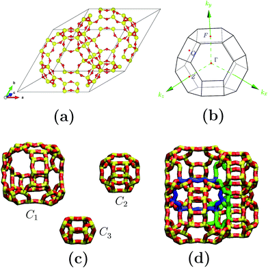
Fig. 1(a) depicts the geometry-optimized primitive cell obtained for siliceous faujasite zeolite. The parameters obtained for this optimized cell were: a = b = c = 17.21 Å, α = β = γ = 60.0°. This primitive cell was employed to reduce the computational costs; once the optimization process had finished it was expanded to obtain the electronic properties in terms of the Brillouin zone corresponding to the conventional unit cell. The unit cell for an FAU zeolite crystal family is cubic and belongs to the Fd![[3 with combining macron]](https://www.rsc.org/images/entities/char_0033_0304.gif) m space group. The Brillouin zone and special symmetry points of interest are shown in Fig. 1(b). In bulk, the crystalline structure for the FAU zeolite can be visualized as the assembly of only three cages C1, C2 and C3 (see Fig. 1(c) and (d)), where C1 is the largest. For siliceous FAU, O atoms have 4 distinct equivalent sites distinguished by the roman subscripts I, II, III and IV, while Si atoms have only one site. Fig. 2 shows the distribution of O and Si atoms in the cages and rings. For the same geometry in a particular cage or ring, oxygen atoms present distinct equivalent sites which are characterized by a different superscript. This is important to note, because although the C2 cage has the same geometry as the siliceous sodalite zeolite, the FAU zeolite presents more than one equivalent site for O atoms.
m space group. The Brillouin zone and special symmetry points of interest are shown in Fig. 1(b). In bulk, the crystalline structure for the FAU zeolite can be visualized as the assembly of only three cages C1, C2 and C3 (see Fig. 1(c) and (d)), where C1 is the largest. For siliceous FAU, O atoms have 4 distinct equivalent sites distinguished by the roman subscripts I, II, III and IV, while Si atoms have only one site. Fig. 2 shows the distribution of O and Si atoms in the cages and rings. For the same geometry in a particular cage or ring, oxygen atoms present distinct equivalent sites which are characterized by a different superscript. This is important to note, because although the C2 cage has the same geometry as the siliceous sodalite zeolite, the FAU zeolite presents more than one equivalent site for O atoms.
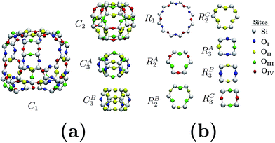 | ||
| Fig. 2 Oxygen and silicon equivalent sites in: (a) cages and (b) elemental ring structures. Different colors identify atoms in equivalent sites. | ||
3 Theoretical methodology
Three different frameworks were considered for the calculations presented here: (a) siliceous Si42O96 faujasite (FAU), (b) AlSi41O96 (FAUI) and (c) Al2Si40O96 (FAUII). We obtained the aluminized framework FAUI by substituting a Si atom by an Al atom at the interface between the two C1 cages (see blue circuit in Fig. 1(d)), and subsequently a neighbor O atom was protonated. FAUII was obtained by substituting a second Al atom (diametrically opposed to previously protonated O atom) by an Al atom in the FAUI framework. We observed that while for the FAUI optimized configuration it was possible to protonate an O atom, the optimized framework of FAUII did not accept a second protonated O atom. Most calculations relative to composites were addressed by embedding M2 (M = Ni, Cu, Fe and Au) clusters in the FAUII zeolite framework.The search for the ground state structures of the faujasite frameworks and composites was performed by using a geometrical optimization through the DFT method, using the DMol3 program package.29–31 For this task, the Becke, Lee, Yang and Parr (BLYP) gradient-corrected functional32,33 was employed for the exchange–correlation energy. The expansion of wave functions of the different atomic species under consideration was studied using the double numerical with a d and p polarization (DNP) basis set (comparable to 6-31G, 6-31G(d) and 6-31G(d,p) Gaussian-type basis sets),30 thus taking into account the electron interactions reasonably. Additionally, multiplicity was set to automatic in our all-electron computations.
4 Results
Fig. 3 depicts the band structure for the different configurations (both frameworks and composites) under study. As shown, the substitution of Al by Si atoms in the siliceous FAU framework increases the band gap energy (as is also shown in Table 1). Fig. 3(d)–(h) show that the energy band structure of a framework shifted down due to the embedding of a cluster. This behavior is not unique to faujasite; it has also been previously observed in erionite and mordenite zeolites.27,28 The reduction of the band gap energy has been ascribed to the insertion of clusters of electron states in the band gap region of the framework. In addition, from Fig. 3(e) and (g) it can be seen that there is a difference between the α and β spin in the FAUII-Cu2 and FAUII-Au2 composites. For clarity, a zoomed region around −2 to 5 eV of these composites is displayed in Fig. 4. As shown in Fig. 4, for FAUII-Cu2 and FAUII-Au2, unfolding bands were presented close to the Fermi level. A comparison of the band gap energy (Eg) values for composites FAU-Cu2 and FAUII-Cu2 (see Table 1), shows that the unfolding band in FAUII-Cu2 decreases this Eg value. This kind of unfolding bands has also been reported previously27 for a composite formed with siliceous erionite and a Cu2 cluster. Nonetheless, for faujasite, the inclusion of Al atoms in the framework was required to promote the unfolding band effect, which is more than evident for the composite FAUII-Au2.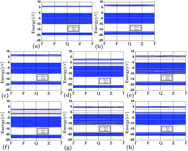 | ||
| Fig. 3 Band structure for frameworks and composites: (a) FAU, (b) FAUI, (c) FAUII, (d) FAU-Cu2, (e) FAUII-Cu2, (f) FAUII-Fe2, (g) FAU-Au2 and (h) FAU-Ni2. | ||
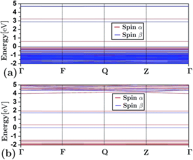 | ||
| Fig. 4 Zoomed region around the Fermi level for band structure that presents the composites: (a) FAUII-Cu2 and (b) FAUII-Au2. | ||
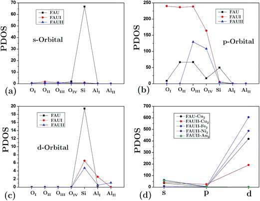
The partial density of states (PDOS) for atoms in the empty frameworks are shown in Fig. 5(a)–(c). The main contribution (at the Fermi level) comes from the [O] 2s orbital and, in lower proportion, from the [Si] 3s and [Si] 3d orbitals. It is very well known that in contrast to faujasite, the participation of silicon orbitals in mordenite and erionite for siliceous empty frameworks is practically null.27,28 On the other hand, a drastic change was also observed in the participation of the aforementioned orbitals when Al atoms replaced Si atoms. Fig. 5(d) shows only the orbitals from clusters at the Fermi level, this due to the shifting of the band structure that frameworks undergo when a cluster is embedded. This figure also shows that the composites with the lowest band gap energy, FAUII-Au2 and FAUII-Ni2, exhibit practically no hybridized orbitals (participation of [Au] 6d and [Ni] 3d orbitals), whereas the change observed by FAUII-Cu2 was due to the high attenuation of the [Cu] 3d orbital.
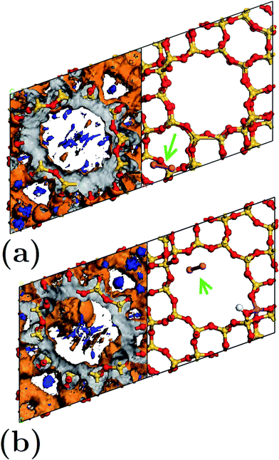
We calculated the average Mulliken charge of atoms within the zeolite framework in different configurations to obtain a qualitative idea of the atomic charge behavior (Fig. 6). In general, oxygen’s equivalent site OII presents the largest Mulliken charge value. When Al atoms substituted O atoms in an empty framework, a decrease of charge for OI decreased as a main effect. On the other hand, when clusters were embedded in frameworks, the charge (both positive and negative) at equivalent sites increased (in magnitude). In Fig. 6, the trace for FAU-Cu2 is not visible due to overlapping of the trace for FAUII-Au2 (both values are very similar). On the other hand, FAUII-Cu2 exhibits the largest charge trace values. Fig. 7 shows the minimum energy configurations and their associated equipotential surfaces (at ±5 eV) for FAU-Cu2 and FAUII-Cu2.
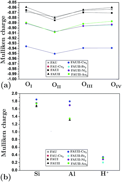 | ||
| Fig. 6 Average Mulliken charge per atom for: (a) oxygen equivalent sites and (b) silicon, aluminum and protons. As reference see Fig. 2. | ||
Detailed analysis indicated that the Cu2 cluster (displayed by an arrow) shown in Fig. 7(a) was localized within a C2 cage with equipotential lines connected to atoms OIII and OIV. By contrast, in Fig. 7(b), the cluster was localized inside a CI cage with equipotential lines mainly connected to an OIII atom. This is in accordance with the traces presented in Fig. 6(a), which refer to those composites where charges on the equivalent sites OIII and OIV show flexibility to change their respective trace. In addition, the maximum equipotential values at which Cu2 clusters bind to framework atoms were calculated, and were found to be ∼5.57 eV and ∼14.9 eV for FAU-Cu2 and FAUII-Cu2 configurations. This shows that a FAUII framework provides a better electrostatic environment to capture a Cu2 cluster than merely a siliceous framework.
5 Conclusions
In this work, the electronic properties of different frameworks and composites of FAU zeolite were computed by the DFT method. Results show that the faujasite framework Al2Si40O96 produces an α and β spin difference of the Cu2 and Au2 clusters and induces an unfolding band structure, favoring a decrease in the energy band gap of the respective composites. In addition, the low energy band gap values are associated with composites in which the cluster presents practically no hybridized orbitals. In comparison to previous work27,28 on mordenite and erionite zeolite composites, we found similar trends in the band structure when the composites were formed; however, the tuning of the cluster orbitals was different. In general, the resulted show that each zeolite framework possesses its own charge trace as a fingerprint. The charge trace presents certain changes that reveal the presence of a cluster inside the zeolite framework: (a) the charge values for all equivalent sites were increased and (b) the signature presented variations for equivalent sites with lower charge values. To be precise, the atoms that occupy those equivalent sites in the zeolite framework are responsible for the adsorption of clusters.Acknowledgements
This research was supported by project SENER-CONACyT Hidrocarburos 117373. APA acknowledges Conacyt-México for the funding project No. 180424. The authors thank A.G. Rodriguez and J. A. Peralta for their kind technical support during this work. María Isabel Pérez Montfort corrected the English version of this manuscript.References
- D. W. Breck, Zeolite Molecular Sieves: Structure, Chemistry, and Use, Wiley & Sons, New York, 3rd edn, 1974, p. 771 Search PubMed.
- C. Baerlocher, L. B. McCusker and D. H. Olson, Atlas of zeolite framework types, Elsevier, Amsterdam, The Netherlands, 6th edn, 2007, p. 405 Search PubMed.
- A. K. Cheetham and P. Day, Solid State Chemistry: Volume 2: Compounds, Clarendon Press, 1st edn, 1992, p. 320 Search PubMed.
- M. E. Davis, Ind. Eng. Chem. Res., 1991, 30, 1675–1683 CrossRef CAS.
- P. G. Savva and C. N. Costa, Catal. Rev., 2011, 53, 91–151 CAS.
- A. V. Salker, Indian J. Chem. Technol., 2004, 11, 683–687 CAS.
- D. Wang, Z. Hao, D. Cheng, X. Shi and C. Hu, J. Mol. Catal. A: Chem., 2003, 200, 229–238 CrossRef CAS.
- A. Simakov, I. Tuzovskaya, N. Bogdanchikova, A. Pestryakov, M. Avalos, M. Farias and E. Smolentseva, Catal. Commun., 2008, 9, 1277–1281 CrossRef CAS.
- S. Tsubota, T. Nakamura, K. Tanaka and M. Haruta, Catal. Lett., 1998, 56, 131–135 CrossRef CAS.
- A. Ueda, Appl. Catal., B, 1998, 18, 115–121 CrossRef CAS.
- E. D. Park and J. S. Lee, J. Catal., 1999, 186, 1–11 CrossRef CAS.
- E. Smolentseva, V. Gurin and V. Petranovskii, Rev. Mex. Ing. Quim., 2012, 11, 469–474 CAS.
- C. López-Bastidas, E. Smolentseva, V. Petranovskii and R. Machorro, Plasmonics, 2013, 8, 1551–1558 CrossRef.
- E. Smolentseva, C. López-Bastidas, V. Petranovskii and R. Machorro, Appl. Surf. Sci., 2014, 321, 136–143 CrossRef CAS.
- P. L. Dubov, D. V. Korolkov and V. P. Petranovskii, Clusters and matrix isolated cluster superstructures, House of St. Petersburg State University, St. Petesburg, 1995 Search PubMed.
- P. K. Dutta, J. Inclusion Phenom. Mol. Recognit. Chem., 1995, 21, 215–237 CAS.
- R. E. Galian and J. Perez-Prieto, Energy Environ. Sci., 2010, 3, 1488–1498 CAS.
- M. N. Chrétien, Pure Appl. Chem., 2007, 79, 1–20 CrossRef.
- P. Reynolds, On clusters and clustering: from atoms to fractals, North-Holland, Amsterdam, 1993 Search PubMed.
- E. Fois, A. Gamba and E. Spano, Phys. Chem. Chem. Phys., 2001, 3, 1877–1882 RSC.
- J. P. Perdew, Int. J. Quantum Chem., 1985, S19, 497–523 Search PubMed.
- M. K. Y. Chand and G. Ceder, Phys. Rev. Lett., 2010, 105, 196403 CrossRef PubMed.
- S. V. Faleev, M. van Schilfgaarde and T. Kotani, Phys. Rev. Lett., 2004, 93, 126406 CrossRef PubMed.
- C. Rödl, F. Fuchs, J. Furthmüller and F. Bechstedt, Phys. Rev. B: Condens. Matter Mater. Phys., 2009, 79, 235114 CrossRef.
- M. C. Toroker, D. K. Kanan, N. Alidoust, L. Y. Isseroff, P. Liao and E. A. Carter, Phys. Chem. Chem. Phys., 2011, 13, 16644–16654 RSC.
- N. Alidoust, M. C. Toroker and E. A. Carter, J. Phys. Chem. B, 2014, 118, 7963–7971 CrossRef CAS PubMed.
- J. Antúnez-García, D. H. Galván, A. Posada-Amarillas and V. Petranovskii, J. Mol. Struct., 2014, 1059, 232–238 CrossRef.
- J. Antúnez-García, D. H. Galván, V. Petranovskii and A. Posada-Amarillas, Comput. Mater. Sci., 2015, 106, 140–148 CrossRef.
- Software from Accelrys Inc., http://www.accelrys.com.
- B. Delley, J. Chem. Phys., 1990, 92, 508–517 CrossRef CAS.
- B. Delley, J. Chem. Phys., 2000, 113, 7756–7764 CrossRef CAS.
- A. D. Becke, Phys. Rev. A, 1988, 38, 3098–3100 CrossRef CAS.
- C. Lee, W. Yang and R. G. Parr, Phys. Rev. B: Condens. Matter Mater. Phys., 1988, 37, 785–789 CrossRef CAS.
| This journal is © The Royal Society of Chemistry 2016 |

