DOI:
10.1039/C6RA12792D
(Paper)
RSC Adv., 2016,
6, 58628-58640
Graphene as a chain extender of polyurethanes for biomedical applications†
Received
17th May 2016
, Accepted 2nd June 2016
First published on 2nd June 2016
Abstract
Amine-functionalized graphene has been chemically tagged within long-chain polyurethane molecules, using graphene as a chain extender to prepare a nanohybrid, and its novelty has been explored by comparing its properties with those of physically dispersed functionalized graphene in polyurethane based on di-ol as a chain extender. Chemical tagging has been confirmed through NMR studies and the nature of the interaction between the polymer matrix and graphene (nanofiller) is stronger in the chemically tagged nanohybrid compared to a nanohybrid prepared through physical mixture, as revealed from FTIR, UV-visible and PL spectroscopic measurement. A homogeneous dispersion of graphene platelets is achieved through a chemically tagged nanohybrid as against the agglomerated nanostructure found in a physically mixed nanohybrid. Enhancement of thermal properties and toughening of the nanohybrids is observed, whose extent is significantly higher in the chemically tagged nanohybrid due to greater interactions between the components and the uniform dispersion of nanofiller. Graphene-induced self-assembly from the nanometer scale to the micron level (step by step) was investigated through X-ray diffraction, small angle neutron scattering, atomic force microscopy and optical images in the order of nanometer, tens of nanometer, hundreds of nanometer and micron size, respectively. The effects of self-assembly on drug release and the biocompatible nature of the nanohybrids were monitored using HeLa cells, looking at cell viability, cell adhesion and fluorescence imaging. Significant sustained release of an anti-cancer drug was obtained using the chemically tagged nanohybrid and understanding gained of its kinetic behavior and mechanism. The greater biocompatibility of the chemically tagged nanohybrid was revealed through cell adhesion and fluorescence imaging, demonstrating a superior biomaterial which delivers the anti-cancer drug in a sustained manner. Hence, the developed nanohybrid is a potential biomaterial for drug delivery and tissue engineering.
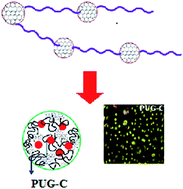
Introduction
Polyurethane, a polymeric material, is used in biomedical applications because of its biocompatibility, easy processability and great mechanical strength which is close to that of natural tissues.1,2 Polyurethanes (PU) are extensively used as adhesives, synthetic leathers, foams, coatings, construction materials, flame retardants, cushion materials, wound dressings and other biological applications.3–9 It is synthesized using diol, diisocyanate and a chain extender. The properties of the polymer can be altered by changing the composition and chemical constituents used during synthesis or by incorporation of a filler into the polymer matrix.10 Polyurethane consists of hard and soft segments and these segments determine the properties of the overall polymer. A soft segment arises from the poly-ol part while a hard segment appears to come from the diisocyanate or is associated with urethane linkages. Self-assembly, which is a common phenomenon in block copolymers11,12 and dendritic polymers,13–15 is also reported in aliphatic polyurethane and it plays a very important role in altering the properties of the polymer. Self-assembled polymeric materials show better thermal and mechanical stabilities over conventional micelles and are expected to enhance the biological activities of the polymer as well.16
A wide range of nanoparticles including metals and their oxides,17–19 nanoclays,20 and CNTs21 in different forms are frequently used to modify the structural, mechanical and biological properties of the polymer.22 Recently, graphene, an sp2 hybridized carbonious material, has drawn tremendous attention in the field of hybrid materials due to its exceptional thermal,23 mechanical,24 optical25–27 and electrical properties.28,29 Graphene or its derivatives are frequently used in composite materials,30–32 sensors,33 catalysis,34 electronics,35 and as carriers for drugs or genes in biomedical fields.36 Due to its high aspect ratio, graphene provides a large interfacial area which is available to the polymer for interactions, and which helps to improve the properties of the pristine polymer.37 There are several reports38–40 of polyurethane hybrid materials containing graphene as the filler, but most of them are physical mixtures of graphene (rarely functionalized) and PU. Incorporation of graphene within the polymer chain is a new idea for making nanohybrids where the graphene moieties are chemically connected to polyurethane chains.
This article reveals the important effects, especially on biological activity, of polyurethane when graphene is chemically tagged with a polymer chain in comparison to the properties when the same graphene is physically dispersed in the polyurethane matrix. Chemical tagging has been confirmed through NMR and other spectroscopic techniques. A comparative study of the physical blend of graphene and PU with the chemically tagged modified graphene within polyurethane chains was made, looking at interactions, morphological features, structures and therefore biological applications. FTIR, UV-visible and PL spectroscopy were used to monitor the interaction between the polymer matrix and amine-modified graphene oxide and to differentiate between the two types of nanohybrid containing a similar amount of nanofiller. Significant improvements in thermal and mechanical properties of the nanohybrid are reported and there is a considerable improvement in the chemically tagged nanohybrid compared to a conventional nanohybrid. Biodegradation was studied, showing sustained degradation in the nanohybrid vis-à-vis pure polymer. Graphene-induced self-assembly was explored using nanometer to micron sized inhomogeneities and their effects on drug release and other biological aspects were studied, including biocompatibility and cell adhesion to determine the efficacy of chemical tagging of graphene within polyurethane chains. The developed nanohybrid exhibits good biocompatibility, and since it also showed sustained drug release, this class of material is superior to conventional composites using the same filler.
Experimental
Materials
Poly(tetramethylene glycol) (PTMG) (Sigma-Aldrich, number-average molecular weight, Mn = 2900 g mol−1), 1,6-hexamethylene diisocyanate (HMDI), and 1,4-butane diol (BD) (Sigma-Aldrich) were used as received. The catalyst dibutyltindilaurate (DBTDL) and solvent, dimethyl formamide (DMF) were purchased from Himedia and Merck, respectively.
Synthesis of graphene oxide
Synthesis of graphene oxide was done through a modified Hammer's method.41 Graphite flakes (3.0 g, 1 wt equiv.) were added to a 9
:
1 ratio of concentrated H2SO4 and H3PO4 (360
:
40 ml), followed by slow addition of KMnO4 (18.0 g, 6 wt equiv.). Then the reaction temperature was increased up to 50 °C with continuous stirring for 12 h. Ice water and 30% H2O2 were added after the reaction mixture was cooled and centrifuged at 4000 rpm. The solid product was repeatedly washed with a mixture of distilled water, 30% HCl and ethanol. Finally, the sample was washed with distilled water until the medium reached neutral pH. The solid obtained was dried at 70 °C for 48 h under reduced pressure in a vacuum oven.
Synthesis of amino modified graphene oxide
Amine modification of graphene oxide was done using ammonia solution, as reported by Lin J. et al.42 500 mg of graphene oxide was introduced into ethylene glycol followed by ultrasonication for 30 min. Further ammonia solution was added and the reaction mixture kept at 180 °C for 12 h with continuous stirring. The color of the reaction mixture changed from yellowish to dark brown. A brownish solid material was obtained after filtration and the material had been repeatedly washed with distilled water. The solid material was dried at 70 °C for 48 h under reduced pressure.
Synthesis of polyurethane and its nanohybrids
Butane diol based polyurethane (BD-PU) was synthesized in two steps: prepolymer preparation using PTMG and HMDI followed by the addition of the chain extender BD. DMF was used as the solvent and a catalyst (DBTDL: 0.1 ml of 1 wt% toluene solution) was used to enhance the reaction rate and the polymerization process was completed with rapid stirring at 70 °C for 24 h. The molar ratio of PTMG
:
HMDI
:
BD was kept at 1
:
5
:
4. The polymer flakes were obtained by pouring the solution into deionized water and drying it at 70 °C for 48 h under reduced pressure. The hard-segment content of the polymer was maintained at 30% by using a predetermined amount of polyol, diisocyanate and chain extender. The physically dispersed nanohybrid of the polymer was prepared by dispersing the modified graphene at the last stage of polymerization. The chemically tagged graphene nanohybrid was synthesized by the addition of amine-functionalized graphene oxide into the prepolymer solution and continuing the chain-extended reaction for 24 h, similar to the BD chain-extended system. Henceforth, the physically mixed and chemically tagged graphene nanohybrids will be termed PUG-P and PUG-C, respectively. The molecular weights of the polymer and its nanohybrids were found to be ∼17
000 Da with a polydispersity index (PDI) ∼1.6, as measured using gel permeation chromatography with DMF as eluent at 70 °C with a 1 mL min−1 flow rate. Scheme 1 represents the preparation of amine-functionalized graphene and the chemically tagged graphene chain-extended nanohybrid (PUG-C), where graphene becomes a part of the polymer chain as against physically dispersed functionalized graphene in a polyurethane matrix. The following are the three different reaction steps in the synthesis of pure PU and two different nanohybrids.
 |
| Scheme 1 (a) Reaction scheme showing the modification of graphene oxide and polyurethane tagging with graphene sheet, (b) cartoon showing (i) physical mixture of graphene and PU chain and (ii) chemical tagging of polyurethane with a graphene sheet. | |
Structural analysis
X-ray diffraction was performed using a Rigaku miniflex 600X-ray diffractometer with a graphite monochromator using a Cu Kα source with a wavelength of 0.154 nm. The generator was kept at 40 kV and 20 mA. Thin films of the samples, prepared through a solution casting technique, were placed on a quartz sample holder at room temperature at a scanning rate of 1° min−1. Small angle neutron scattering (SANS) experiments were done on a spectrometer at Dhruva reactor under Bhabha Atomic Research Centre, Mumbai, India. The SANS experiment was performed in the scattering vector (q) range of 0.17 nm−1 ≤ q ≤ 3.5 nm−1. The scattering from the samples was corrected for background contributions. Debye–Bueche and other models were fitted separately in the lower range of q. The characteristic length (Λc) was obtained from the equation Λc = 2π/qm, where qm is the scattering vector q corresponding to the peak position in the scattering pattern and the temperature of the experiment was kept constant at 30 °C.
Spectroscopic measurements
A Fourier transform infrared (FTIR) spectrum was taken in reflectance mode at room temperature from 400 to 4000 cm−1 using a Nicolet 6700 FTIR with a resolution of 4 cm−1. The UV-visible measurement was made in the range of 200 to 800 nm in the reflectance mode using solid specimens (JascoV-650).
Thermal studies
The melting point and heat of fusion of PU and its nanohybrids were measured using a differential scanning calorimeter (DSC, Mettler 832) over a temperature range of −30 to 200 °C at a scan rate of 10° min−1. The peak temperature and heat of fusion were obtained from the endotherms using a computer attached to the instrument. The thermal stability of the polymer and its nanohybrids were studied with a thermogravimetric analyzer (TGA, Mettler-Toledo) in the temperature range from 40 to 600 °C. All the experiments were done at a heating rate of 20° min−1 under a nitrogen atmosphere.
Morphological investigation
Dispersion of modified graphene in a PU matrix was viewed through TEM (FEI Technai 20) operating at a voltage of 200 kV. The morphology of PU and its nanohybrids was studied through an optical microscope and atomic force microscope (AFM). AFM was done using a NT-MDT multimode AFM (Russia), controlled by a Solver scanning probe microscope controller. Semi-contact mode was used, with the tip mounted on a 100 μm long, single beam cantilever with a resonant frequency in the range of 240–255 kHz, and corresponding spring constant of 11.5 N m−1. The surface morphology of the thin films in the optical range was studied with an optical microscope (Leica). Thin samples were prepared through the solvent casting technique for optical measurements.
Mechanical responses
For mechanical studies, we used a universal testing machine (UTM) in tensile mode. Standardized samples were prepared through an injection moulding technique using a microinjector (model FD-1, Fly Tech Engineering). The samples were microinjected at a barrel temperature of Tm + 20 °C and a mold temperature of 40 °C with a pressure of 100 bars. Tensile tests of the samples were performed using an Instron 3369 tensile tester at a strain rate of 5 mm min−1 at room temperature, with specimen dimensions of 25 mm gauge length, 4.05 mm breadth, and 2.12 mm thickness. Several samples were analyzed to minimize the error.
Drug assay and release
An anti-cancerous, dexamethasone standard stock solution (1 mg ml−1) was prepared first. A standard curve was drawn after taking absorbance measurements using a UV-visible spectrophotometer (Jasco V-650), taking the absorbance at 242 nm in the concentration range of 1–100 μg ml−1. In vitro release studies were done in PBS buffer at pH ∼7.4. Drug-loaded polyurethane and its nanohybrid specimens, prepared through the solution route, were allowed to stir into 100 ml of released medium in an incubator shaker at 100 rpm at 37 °C. Aliquots were taken from the release medium at constant time intervals and the same quantity was replaced with fresh buffer. The concentration of drug in the release media was measured by taking absorbance at 242 nm.
Enzymatic degradation
Enzymatic degradation of PU and its nanohybrids was studied using lipase at 37 °C in a phosphate buffer solution (pH 7.4) containing 0.2 mg ml−1 enzyme. PU and its nanohybrids sheets with dimensions of 8 × 7 × 0.5 mm3 were introduced into vials containing 5 ml of phosphate buffer. Those vials were incubated at 37 °C with constant shaking. Samples were taken from the vials, washed with distilled water three or four times to remove surface materials from the samples and were dried under vacuum before analysis. The extent of biodegradation is considered to be the weight loss percentage.
Contact angle measurement
Contact angles of the samples were measured with a Kruss Tensiometer K-100 for evaluation of the hydrophilic nature of the surface. To avoid error every sample was measured in triplicate.
Cell culture
HeLa cells were cultured in Dulbecco's modified Eagle's medium (DMEM), supplemented with 10% heat-inactivated fetal bovine serum (Himedia, Mumbai), penicillin (100 U mL−1) and streptomycin (100 mg mL−1) at 37 °C in a humidified CO2 incubator (Thermo Scientific), maintained at 5% CO2.
Cell viability
Cell viability was evaluated using MTT (4,5-dimethylthiazol-2-yl-2,5-diphenyltretrazolium bromide) assay. Cells were seeded in 96 well plates at a density of 1 × 10⁴ cells per well and were incubated at 37 °C for 24 h. Then supernatant media including dead cells were replaced with 200 μl fresh media in each well. Test specimens were released into each well after sterilization with 70% ethanol followed by UV exposure, and incubated for 1, 3 and 5 days. 50 μl of 0.5 mg ml−1 MTT solution in DMEM without FBS were introduced into each well and the mixture was incubated for 4 hours at 37 °C and finally the MTT-containing medium was removed and 100 ml of DMSO (SRL, Mumbai, India) were added to each well to solubilize the water-insoluble formazan. Absorbance was taken using a Microplate reader (iMark, Biorad) at 570 nm. The percentage cell viability was calculated using the following formula;
% of cell viability = [(OD of S) − (OD of Ctrl+)/(OD of Ctrl−)] × 100 |
where Ctrl− is a negative control i.e. the cells incubated with the medium alone, Ctrl+ is a positive control i.e. the cells incubated with the medium and 10% DMSO, and S is the test sample.
Cell adhesion
To examine the cell adhesion properties of PU and its nanohybrids, 1 × 10⁴ cells per well of a 96-well plate were seeded on various specimen surfaces and were incubated in a CO2 incubator for 4 h. Then the specimens were washed with PBS to remove the unattached cells and the specimens with attached cells were incubated with MTT solution in DMEM without FBS for 4 hours at 37 °C. The specimens were kept in the wells with 100 μl DMSO for 15 min to solubilize the formazan. Absorbance was measured using the Microplate reader at 570 nm. The optical density values obtained were correlated directly with the number of attached cells and compared with the cells attached to the bottom of the wells.
Percentage cell adhesion was calculated using the following formula:
% cell adhesion = (OD of S)/(OD of C) × 100 |
where C is the optical density value of the control,
i.e. the cells attached to the bottom of the well, and S is optical density values of the sample.
Fluorescence studies
The effect of pure polymer and its nanohybrids on cell proliferation was studied through a fluorescence microscopic technique in which cells were seeded in 24 well plates at a density of 1 × 10⁴ cells per ml and incubated for 24 h at 37 °C. Supernatant media including dead cells were replaced with fresh media in each well and specimen samples were released into each well after sterilization and were incubated for another 24 hours at 37 °C. Then, the cells were washed twice with 10 mM PBS, stained with fluorescent dye, acridine orange and ethydine bromide (Sigma) (100 μg mL−1), and were incubated in the dark for 30 min at room temperature. Images were taken using a fluorescence microscope (Dewinter Technologies, India).
Results and discussion
Functionalized graphene as chain extender
Amine-functionalized graphene was dispersed in a polyurethane matrix in two different ways: (i) physical dispersion where graphene sheets were distributed in the PU matrix like a conventional composite through the solution route, and (ii) chemical dispersion where graphene sheets were chemically tagged with polyurethane chains using amine-functionalized graphene as a chain extender for the synthesis of PU as shown in Scheme 1. In a strict sense, it is not a graft copolymer but functionalized graphene acts as a chain extender and graphene becomes part of the polymer chain. The formation of a chemically tagged graphene oxide nanohybrid was confirmed from NMR spectroscopy where new peak arose at δ = 8.17 ppm at a lower field due to the
N–H proton adjacent to the graphene sheet (Fig. 1). The 1H signal for regular
N–H groups present in urethane linkages appears at δ = 7.0 ppm both for pure PU and composites, while the peak intensity was reduced considerably for the chemically tagged nanohybrid due to its lower abundance, as half of the –NCO groups of diisocyanate are chemically linked to amine-functionalized graphene. Further, the high field peaks associated with methylene groups (–CH2–) either in hexamethylene diisocyanate or polyol have split into a couple of peaks in the chemically tagged graphene nanohybrid (PUG-C) due to a change in the electronic environment linked with amine-functionalized graphene. In contrast, no such splitting or shifting of the peaks occurs in the physically tagged nanohybrid (PUG-P) compared to pure PU. However, NMR studies confirm the chemical tagging of the graphene sheet with polyurethane chains.
 |
| Fig. 1 1H-NMR spectra of the pure PU and its indicated nanohybrids. | |
Nanostructure and interactions
Physically mixed nanohybrids (PUG-P) were prepared by the addition of modified graphene at the end of the polymerization process, followed by mixing for a sufficiently long time. The highly agglomerated nanostructure of the graphene sheet is observed through TEM bright field images (Fig. 2a). On the other hand, chemically grafted graphene nanohybrids (PUG-C), synthesized using amine-functionalized graphene as a chain extender, exhibit homogeneous dispersion of graphene sheets in the PU matrix and are expected to show better properties than PUG-P for a similar content of graphene. Chemical tagging of graphene within the polyurethane chain has a significant influence on the nature of the interactions. FTIR and UV-visible spectra of modified graphene oxide are presented in ESI Fig. S1.† The appearance of the FTIR band at 1571 cm−1 in modified graphene indicates the presence of a
N–H moiety in amine-functionalized graphene after treatment with ammonia, with the disappearance of C–OH and
C
O peaks of graphene oxide at 1398 and 1745 cm−1, respectively.42 The addition of ammonia solution to graphene oxide suspension also promotes the dehydration reaction by removing the hydroxyl groups. Due to this reorganization of the structure of modified graphene (GM), its spectra revert towards those of pristine graphene, as verified by the shifting of the UV-visible peak to 273 nm from the peak at 307 nm of graphene oxide (Fig. S1†). Pure polyurethane shows an FTIR absorption peak at 1680 cm−1 due to the hydrogen-bonded urethane moiety which remains unchanged in the physically tagged graphene nanobybrid while there is a slight shift observed in the free
N–H stretching frequency in PUG-P (Fig. 2b).43 On the other hand, the hydrogen-bonded peak has been significantly reduced in the chemically tagged nanohybrid (PUG-C) and a considerable shift occurs for the free
N–H stretching frequency in the presence of the adjacent constrained graphene moiety (Scheme 1). A slight shift in the hydrogen-bonded peak reflects greater interaction between the hard-segment
N–H group of PUG-C and the rest of the polymer chain. The shift of the
N–H stretching frequency for PUG-C to 3325 cm−1 from the original peak position at 3319 cm−1 for pure PU also suggests a strong interaction between the graphene sheet and the polymer chain against the unaltered frequency for PUG-P (ESI Fig. S2†). Further, a prominent red shift for the nanohybrid due to a π → π* transition in the UV-vis absorption spectra compared to pure PU also confirms the good interaction between graphene and the polymer chains (Fig. 2c).44 Moreover, a larger shift in PUG-C confirms the greater interaction when graphene is chemically tagged with the PU chain vis-à-vis physical dispersion of graphene in PUG-P. Fig. 2d shows the photoluminescence spectra of polyurethane and its nanohybrids excited at 275 nm, as determined from the absorption spectra. Both the nanohybrids show broad PL emission spectra originating from a π* → π transition of the graphene moiety.45 The peak position of the transition is shifted towards a higher wavelength (393 to 402 nm from graphene to PUG-C) due to electronic redistribution arising from greater interactions between the polymer chain and modified graphene, whereas there is no change of peak position observed in PUG-P. The appearance of the peak band at 441 nm in GM and nanohybrids is due to an n → π transition and no shifting is observed in the emission patterns. It is worth mentioning that the emission pattern from PU is reflected in the nanohybrids having a wider spectrum compared to modified graphene spectra. The generation of the lower wavelength peak band at 319 nm is reported to be a coupling between the π* → π and n → π transitions.45 Further, the shift of a peak in the Raman spectra observed at 1726 cm−1 for the carbonyl group for the chemically tagged nanohybrid in comparison to the peak position of 1721 cm−1 for pure PU also indicates considerable interaction between the components of the chemically tagged nanohybrid (ESI Fig. S3†). It should be mentioned that the peak position for the physically mixed nanohybrid is at 1723 cm−1.
 |
| Fig. 2 (a) TEM image of PUG-P and PUG-C (b) FTIR spectra of the pure PU and its indicated nanohybrids. (c) UV-visible spectra of the modified graphene with physically and chemically tagged nanohybrids (UV-visible spectra of pure PU inset) and (d) PL spectra of pure PU and its indicated nanohybrids with modified graphene. | |
Two nanohybrids were developed, (i) by dispersing the graphene sheet in polymer through the solution route where the nanofillers physically adhere to the polymer matrix, and (ii) graphene sheets becoming part of a long polymer chain by using amine-functionalized graphene as chain extenders where individual graphene sheets are homogeneously distributed in the PU matrix compared to the agglomerated nanostructure seen in the physically dispersed nanohybrid (PUG-P). Because of their good dispersion and because they are part of the polymer chain, the graphene sheets have good interaction with the polymer chains, predominantly through dipolar interactions between the π-electron cloud of the graphene sheet and the urethane linkages of PU and this reflected in spectroscopic measurements. In pure PU, extensive hydrogen bonding occurs amongst the urethane linkages, which provides a strong FTIR peak at 1680 cm−1 and maintains minimal intensity of the free
N–H group l while the free
N–H absorption is prominent at 1725 cm−1. There is a considerable shift in PUG-C as the amine groups in proximity to the graphene sheets are unable to form hydrogen bonds. Further, better interactions in chemically linked graphene with the polyurethane chain are evident in the greater red shift, either in UV-vis absorption or emission spectroscopy, compared to graphene physically adhered to PU chains.
Effect of graphene on structure, stability and morphology
Fig. 3a shows the XRD patterns of pure PU and its nanohybrids, indicating the crystalline structure of pure PU while the crystallinity is significantly reduced in the nanohybrids. Pure PU exhibits a sharp peak at 24.8° presumably due to crystallinity arising from the hard-segment zone. The intensity of this peak decreases in the nanohybrids, indicating their increasingly amorphous nature even in the hard-segment region, mainly because of the constraints of the graphene sheet which do not allow the polymer chain to become crystallized. Further, the peak at 22.3° becomes broader in nanohybrids compared to pure PU and this broadening is more pronounced in the chemically grafted nanohybrids, suggesting an even greater reduction in crystallinity. DSC thermograms of pure PU and its nanohybrids show double endothermic peaks for soft- and hard-segment melting (Fig. 3b). Lower endothermic peaks represent the melting behavior of soft segments arising from diol while higher endothermic peaks represent the melting of hard segments.46 The heats of fusion corresponding to the hard-segment zone remain similar (∼6 J g−1) for pure PU and PUG-P, while a considerable reduction occurs in PUG-C as the graphene sheet adjacent to a hard segment does not allow the polymer chains to crystallize in the chemically tagged nanohybrid. On the other hand, heats of fusion for soft-segment melting increase to 18, 26 and 28 J g−1 for pure PU, PUG-P and PUG-C, respectively, indicating the nucleating behavior of graphene in the crystallization of soft segments.
 |
| Fig. 3 (a) XRD pattern of the pure PU and its indicated nanohybrids (XRD of modified graphene inset), (b) DSC thermograph of polyurethane and its nanohybrids, (c) TGA curve of the pure polymer and its nanohybrids and (d) SEM image of modified graphene with physically and chemically tagged nanohybrids. | |
Fig. 3c shows the thermal stability of PU and its nanohybrids against temperature, measured using a thermogravimetric analyzer. The degradation temperatures, corresponding to a weight loss of 5%, occur at 285, 310 and 343 °C for pure PU, PUG-P and PUG-C, respectively, indicating much greater thermal stability of polymer chains in the presence of graphene sheets. The higher thermal stability (of more than 50 °C) of the chemically tagged nanohybrid is due to the homogeneous dispersion of thermally stable graphene layers in the polymer matrix. Moreover, two stages of degradation are observed both for the pure polymer and its nanohybrids due to the separate degradation of the hard and soft segments and to the hard segments being susceptible to temperature degradation at a lower temperature, followed by degradation of the soft segments at a higher temperature.46 Interestingly, the slope of the degradation kinetics of the PUG-C hard segment is considerably lower than the steep degradation seen in pure PU, due to the significantly lower aggregation of the hard segments of the chemically tagged nanohybrid, as discussed above. So, the diffused hard segment in PUG-C vis-à-vis pure PU and PUG-P enhances the degradation kinetics to higher temperature. However, the crystalline nature (grains) of amine-functionalized graphene is evident in its surface morphology through SEM, while a cloth-like morphology is clearly observed in the nanohybrids, indicating their amorphous behavior (Fig. 3d and ESI Fig. S4†). The uniform distribution of the graphene sheet is also observed in PUG-C compared to PUG-P, as previously seen in the TEM bright field image.
Graphene-induced toughening in polyurethane
Mechanical strength testing through uniaxial stretching of polyurethane and its nanohybrids is presented in Fig. 4a. Nanohybrids exhibit higher elongation at break compared to the pure polymer and the chemically tagged graphene nanohybrid shows much higher elongation at break compared to PUG-P. Toughness, as measured from the area under the stress–strain curve, increases for nanohybrids compared to pure polymer (Fig. 4b). Further, this enhancement in toughness is more pronounced in the chemically tagged nanohybrid compared to the physically mixed nanohybrid. Easy orientation of the modified graphene sheets towards the applied force is facilitated for the chemically tagged nanohybrid where the graphene sheets are part of the polymer chain. This reorganization of the graphene consumes energy and, thereby, suppresses the crack propagation process, the key factor for the enhancement of toughness in PUG-C. On the other hand, the physically mixed graphene also reorganizes itself a bit due to the frictional force, leading to a considerable increase in toughness in PUG-P.43,47 The initial slopes of the stress–strain curves of the nanohybrids reduce significantly compared to pure PU, leading to a lowering of Young's modulus of the nanohybrids. The higher modulus of PU is explained by its greater crystallinity, where organized hard segments act as reinforcing agents (ESI Fig. S5†). It is worth mentioning that crystallinity in the hard-segmented zone reduces considerably in PUG-C (as observed through DSC and XRD measurements) which makes this system softer (low modulus), and its greater amorphous content enhances its elongation at break to a greater extent.
 |
| Fig. 4 Mechanical behavior of the polymer and its nanohybrids. (a) Stress–strain curve of the polymer and its nanohybrids and (b) toughness of the pure polymer and its indicated nanohybrids. | |
Graphene-induced self-assembly in polyurethane
Aliphatic polyurethane is known for its molecular aggregation through hydrogen-bonded interactions between the hard segments of neighboring molecules. Pure PU exhibits an X-ray diffraction peak at ∼6.3° corresponding to a d-spacing of 1.42 nm, indicating the interplanar distance formed by the molecular sheet (Fig. 5a).10 The peak position remains the same in the physically mixed graphene nanohybrid, while a considerable shift in peak position occurs for the chemically tagged nanohybrid towards a higher angle (lower d-spacing; 1.2 nm), suggesting closer association of the molecular sheet in the presence of graphene. Furthermore, humps in the small angle neutron scattering (SANS) patterns are observed at q ∼ 0.4 nm−1, corresponding to the characteristic lengths, Λc (=2π/qm), of 15.7, 13.5 and 13.4 nm for pure PU, PUG-P and PUG-C, respectively (Fig. 5b). It is worth mentioning that a couple of molecular sheets assemble together to form a greater aggregation and the distance between those two adjacent layers is of the order of ten nanometers. Furthermore, the decrease in the characteristic length for the nanohybrid compared to pure PU is explained by the fact that assembly takes place with a minimum number of polymer chains in the presence of the graphene sheet in the nanohybrid, while a larger number of polymer chains is required to form the aggregate in pure PU. Hence, the graphene sheet in the nanohybrid helps in the self-assembly process. Lowering of the characteristic length in the presence of layered silicate was reported in our previous work, but graphene also facilitates the molecular self-assembly.10,43,47 Moreover, the correlation lengths (ξ) were calculated from the SANS patterns using the Debye–Bueche eqn (1) which provides a value of about 0.8, 1.23 and 1.47 nm for PU, PUG-P, PUG-C, respectively. |
I(q) = I(0)/(1 + ξ2q2)2
| (1) |
where I(q) is the scattered intensity, I(0) is the extrapolated structure factor at zero wavevector, q is the wavevector, and ξ is the correlation length. Debye–Bueche fitting of the calculation of correlation length is given in the ESI Fig. S6.† The correlation length is associated with the blob size and its relatively higher size in the nanohybrid is presumably due to the insertion of graphene sheets within the agglomerates. In comparison with other nanofillers, e.g. layered silicates, the lower correlation length in the graphene-containing nanohybrid arises from differences in interactions between the components.47 The higher order self-assembly is observed through AFM topography where 212 nm inhomogeneities are clearly seen in pure PU whose dimension increases to 245 nm in the nanohybrid (Fig. 5c). Furthermore, greater self-assembly is evident in optical images, with the dimensions of 2.3, 2.9 and 3.1 μm for pure PU, PUG-P and PUG-C, respectively (Fig. 5d). Now it is pertinent to consider the gradual increase in assembly size from 1.4 nm → 15 nm → 212 nm →2.3 μm observed through XRD, SANS, AFM and POM measurements, where one order of increase in assembly size can be seen at every step. This is to say that extensive hydrogen bonding helps the self-assembly to form bigger agglomerates discernable in optical microscopy, starting step by step from the nanometer dimension of the molecular sheet. However, the macroscopic dimension of self-assembly in the graphene nanohybrid is a bit larger in size compared to pure PU, even though the initial assembly size is smaller in nanohybrids. Hence, graphene sheets influence the aggregation of polyurethane in layer-by-layer self-assembly and are expected to alter the biological activities of polyurethanes.
 |
| Fig. 5 (a) XRD pattern of pure PU and its indicated nanohybrids. (b) Small-angle neutron scattering patterns of the pure PU and its nanohybrids. (c) AFM image of the polymer and its nanohybrids (1 μm × 1 μm) and (d) optical image of the pure PU and its indicated nanohybrids. (Scale bar 20 μm). | |
Sustained drug delivery
In vitro drug release in phosphate buffer solution (pH ∼ 7.4) at 37 °C was studied using the drug dexamethasone embedded in pure PU and its nanohybrids. The concentrations of the drug released from the polymer and its nanohybrids were measured through UV-visible absorption studies.48,49 The cumulative percentage release of dexamethasone as a function of time is presented in Fig. 6a. Around 15% burst release, arising from the surface-adhered drug, was noted in pure PU which reduced to 10% in the nanohybrids. Interestingly, overall drug release kinetics were sustained in the nanohybrids compared to pure PU and the chemically tagged graphene nanohybrid exhibited significant sustained release. There are various steps to determine drug release from a polymer matrix, (i) penetration of the liquid into the matrix, (ii) dissolution of the drug and, (iii) diffusion of the drug from the matrix, and any of these steps may be related to the rate-determining step for the overall release kinetics.50 To understand the mechanism, the release kinetics of dexamethasone are best fitted with a Korsmeyer–Peppas model (r2 ∼ 0.998), leading to exponent ‘n’ values of 0.54, 0.70 and 0.72 for pure polymer, PUG-P and PUG-C, respectively, indicating the non-Fickian (n ≥ 0.45) behavior of the drug release (Fig. 6b). Sustained release of the loaded drug in the nanohybrids is due to the drug diffusing out through a tortuous path in the presence of two-dimensional graphene sheets dispersed in a polymer matrix. Further, the greater self-assembly in the nanohybrids hinders the release kinetics, causing sustained release. Moreover, the homogeneous dispersion of the graphene sheets helps sustained release of the drug in PUG-C vis-à-vis PUG-P, where agglomeration of the graphene reduces the tortuous path. A schematic representation of the drug release is shown in Fig. 6c, indicating the tortuous paths in the two different nanohybrids which cause differential release rates. However, the chemically tagged nanohybrid exhibits a higher exponent value compared to pure polymer and PUG-P, indicating slow release due to the presence of two-dimensional graphene sheets. It should be mentioned that release kinetics have been fitted with other models, but the Korsmeyer–Peppas model is found to be the best fitting one, as revealed by its highest r2 value (ESI Table S1†). The rate of biodegradation may also affect the release kinetics and needs to be looked into.
 |
| Fig. 6 (a) Sustained drug release profile of indicated PU and its nanohybrids, (b) Korsemeyer–Peppas model for mechanism of drug release in PU and its indicated nanohybrids and (c) schematic model of drug release kinetics. The black line represents the polymer chains, whereas plates indicate the graphene sheets. Arrows show the probable path for drug diffusion. | |
Enzymatic degradation
Enzymatic degradation of pure PU and its nanohybrids using lipase from Pseudomonas cepacia is presented in Fig. 7. Weight loss is considered to be a measure of biodegradation. Pure polyurethane shows a considerably higher rate of biodegradation compared to the nanohybrids or, in other words, the biodegradation rate is significantly suppressed in the nanohybrids. Further, the rate of biodegradation is slowed in the chemically tagged graphene nanohybrid compared to the physical mixture of graphene in polyurethane. It is well known that the amorphous zone is prone to hydrolysis by the enzyme and the higher crystallinity of the nanohybrids in the soft-segment zones makes them less prone to biodegradation. Though the crystallinity of the hard segment decreases in the nanohybrid, the proximity of the graphene sheet adjacent to the urethane linkage somehow restricts the hydrolysis rate, leading to a lower rate of biodegradation. Since lipase is hydrolytic in nature, it usually attacks the more sensitive amorphous zone of a polymer during biodegradation.47 However, the lower rate of biodegradation for the nanohybrid is partly responsible for the slower drug release against the faster drug release in pure PU, being facilitated through the higher rate of biodegradation where diffusion of the drug occurs easily. Other nanofillers including layered silicates also show sluggish biodegradation rates compared to pure polymers, but the extent of slower biodegradation is greater in the case of graphene-based nanohybrids. Moreover, uniformly dispersed graphene in the chemically tagged nanohybrid exhibits more sluggish behavior vis-à-vis PUG-P.
 |
| Fig. 7 Enzymatic degradation of the pure polymer and its indicated nanohybrids through lipase (Pseudomonas cepacia). | |
Cell viability in nanohybrids
To check for the ability to release the biological molecules in a controlled way, it is necessary to study the biocompatibility of these nanohybrids using a cell line. The cell viability of HeLa cells on the surface of pure PU and its nanohybrids was studied through MTT assay. Cells cultured without polymeric material were taken as the control. Cell viability on pure PU is higher than for its nanohybrids after 1 day of culture, while cell viability increases rapidly with time (Fig. 8a). The cell viability of nanohybrids almost equals that of pure PU after 5 days of culture. Interestingly, the chemically tagged nanohybrid exhibits higher cell viability compared to physically mixed graphene nanohybrids. Polyurethanes are known for their biocompatibility and are being used in many different applications, but graphene is not so biocompatible.51 In contrast, nanohybrids are found to be biocompatible after the graphene sheets have been wrapped in biocompatible polymer. Further, PUG-C shows better cell viability than PUG-P as the graphene sheets are better enfolded, being part of the polymer chain. This result indicates that a nanohybrid with chemically tagged graphene as a filler material exhibits better cell growth than the nanohybrid with physically mixed graphene. Oxidized graphene nanoribbons formed through the longitudinal unzipping of CNTs in a PEG-DSPE (1,2-distearoyl-sn-glycero-3-phosphoethanolamine-N-[amino(polyethylene glycol)]) matrix exhibit a decrease in cell viability of HeLa cells after 24 and 48 h while an amine-functionalized graphene nanohybrid of polyurethane shows much better biocompatibility.52 The biocompatibility of the amine-modified graphene oxide in terms of thrombotoxicity was evaluated by Singh et al. using blood platelets.53 Combining our previous studies and some information reported in the literature, it appears that amine-functionalized graphene helps to improve the biocompatibility of the nanohybrid towards HeLa cells. This observation is further supported through a fluorescence image of the cells using acridine orange and ethydine bromide dyes (Fig. 8b). Cells are healthier on the chemically tagged nanohybrids compared to pure PU and the physically mixed graphene nanohybrid. It was also reported that differentiation of the cells occurred on the surface of graphene oxide.54
 |
| Fig. 8 Biological studies on pure PU and its indicated nanohybrids. (a) HeLa cell viability of pure PU and its nanohybrids with time intervals of 1, 3 and 5 days; (b) fluorescence microscopic image of cell cultured on PU and its indicated nanohybrids after 1 day of cell proliferation. (c) HeLa cell adhesion on PU and its indicated nanohybrids. | |
Cell adhesion
Carbon materials are frequently used as implant materials and in the tissue engineering field due to their inherent biocompatibility.55–60 Cells need to adhere on top of the implant materials for better growth. Cell adhesions of HeLa cells on pure PU and its nanohybrids are presented in Fig. 8c. It can be clearly observed that the chemically tagged graphene nanohybrid exhibits better cell adhesion behavior than pure PU and the physically mixed graphene nanohybrid. Since biocompatible polyurethane is frequently used as an implant material as well as in biomedical devices, the chemically tagged nanohybrid is a better choice with its improved physical properties along with the greater biological activity in terms of cell viability and cell adhesion.61–66 Further, cell adhesion in PUG-C is found to be much greater than that of PUG-P, indicating that chemical tagging is a better approach for nanohybrid preparation. Contact angles of pure PU, PUG-P and PUG-C are found to be 78.2°, 83.8°, and 75.3°, respectively. The lower contact angle value of the chemically tagged nanohybrid with respect to pure PU and the physically mixed nanohybrid promotes cell adhesion on its surface by increasing the hydrophilic nature of the material. However, cell viability, cell imaging and cell adhesion studies confirm the biocompatible nature of the nanohybrids. Between the nanohybrids the chemically tagged hybrid exhibits superior biocompatible nature to the physically mixed nanohybrid. The chemically tagged graphene nanohybrid shows an all-round improvement in properties, starting with higher mechanical and thermal stability, and the release of drug in a sustained manner and, therefore, it has potential for use as a new class of biomaterial with excellent biocompatibility.
Conclusions
Graphene nanohybrids with polyurethane were synthesized using functionalized graphene as the chain extender. The chemical tagging of graphene within the polyurethane chain was confirmed through NMR studies. The superior properties of the chemically tagged nanohybrid were compared with a physically dispersed functionalized graphene nanohybrid. Dispersion of graphene platelets is homogeneous and uniform in the chemically tagged nanohybrid as opposed to the agglomerated nanostructure seen in the physically mixed graphene nanohybrid as observed through bright field TEM images. Greater interaction in the chemically tagged nanohybrid was revealed through FTIR, UV-visible and PL spectroscopic techniques and the results were compared with the physically tagged nanohybrid. The presence of graphene as part of the polymer chain in the nanohybrid makes a difference to dispersion and interaction, which in turn enhance the thermal stability and toughening behavior of the nanohybrid over pure polyurethane and the physically tagged nanohybrid. Graphene platelets induce self-assembly in the polyurethane through close association with the polymer chain and greater interactions as observed through step-by-step self-assembly from nanometer-size to micron-size clusters as observed through XRD, SANS, AFM and optical microscopy. The effect of self-assembly was reflected in drug delivery, causing sustained release in the chemically tagged nanohybrid vis-à-vis pure polyurethane due to the tortuous path in the presence of self-assembled inhomogeneities and two-dimensional graphene platelets. Biocompatibility of this nanohybrid was explored through cell viability, cell adhesion and fluorescence images, indicating better biocompatible material in comparison to the physically tagged graphene nanohybrid. In addition, controlled release of a cancer drug as well as the biocompatible nature of the chemically tagged nanohybrid with its superior thermal and mechanical properties make it an attractive biomaterial for drug delivery and tissue engineering applications.
Acknowledgements
The author (D. K. Patel) gratefully acknowledges the financial support from CSIR/UGC New Delhi in form of fellowship. Authors highly acknowledge the Abhinav Maurya for his kind supports during the experiments. Authors also acknowledge the Prof. Nira Misra School of Biomedical Engineering, IIT-BHU, Varanasi for contact angle measurement. Authors are grateful to Prof. J. K. Roy, Department of Zoology, Banaras Hindu University for Providing HeLa Cells used in the experiments. Authors also acknowledge the Council for Scientific and Industrial Research (Grant No. 02(0074)/12/EMR-II) (CSIR-UGC), New Delhi. Authors gratefully acknowledge Dr Arvind K. Singh, Department of Chemical Engineering, IIT-Delhi for Raman studies.
References
- P. N. Lan, S. Corneillie, E. Schacht, M. Davies and A. Shard, Biomaterials, 1996, 17, 2273–2280 CrossRef CAS PubMed.
- J. Guan, K. L. Fujimoto, M. S. Sacks and W. R. Wanger, Biomaterials, 2005, 26, 3961–3971 CrossRef CAS PubMed.
- S. H. Lee, A. Cyriac, J. Y. Jeon and B. Y. Lee, Polym. Chem., 2012, 3, 1215 RSC.
- A. Cyriac, S. H. Lee and B. Y. Lee, et al., Green Chem., 2011, 13, 3469–3475 RSC.
- X. Gao, Y. Guo, Y. Tian, S. Li, S. Zhou and Z. Wang, Colloids Surf., A, 2011, 384, 2–8 CrossRef CAS.
- H. Xu, J. Chang, Y. Chen, H. Fan and B. Shi, J. Mater. Sci., 2013, 48, 6625–6639 CrossRef CAS.
- E. Camposa, R. Cordeiroa, A. C. Santos and M. H. Gil, et al., Colloids Surf., B, 2011, 88, 477–482 CrossRef PubMed.
- I. D. Molak, M. Lekka and K. J. Kurzydlowski, Appl. Surf. Sci., 2013, 270, 553–560 CrossRef.
- Y. Choi, R. Nirmala, J. Y. Lee, M. Rahman, S. T. Hong and H. Y. Kim, Ceram. Int., 2013, 39, 4937–4944 CrossRef CAS.
- A. Mishra, B. P. D. Purkayastha, J. K. Roy, V. K. Aswal and P. Maiti, Macromolecules, 2010, 43, 9928–9936 CrossRef CAS.
- D. J. Pochan, Z. Chen, H. Cui, K. Hales, K. Qi and K. L. Wooley, Science, 2004, 306, 94–97 CrossRef CAS PubMed.
- S. Jain and F. Bates, Science, 2003, 300, 460–464 CrossRef CAS PubMed.
- A. W. Bosman, H. M. Janssen and E. W. Meijer, Chem. Rev., 1999, 99, 1655–1688 CrossRef.
- E. R. Gillies, T. B. Jonsson and J. M. J. Frechet, J. Am. Chem. Soc., 2004, 126, 11936–11943 CrossRef CAS PubMed.
- J. del Barrio, L. Oriol, C. Sanchez, J. L. Serrano, A. D. Cicco, P. Keller and M. H. Li, J. Am. Chem. Soc., 2010, 132, 3762–3769 CrossRef CAS PubMed.
- B. M. Discher, Y. Y. Won, D. S. Ede, J. C. Lee, F. S. Bates, D. E. Discher and D. A. Hammer, Science, 1999, 284, 1143–1146 CrossRef CAS PubMed.
- S. Saint, J. G. Elmore and T. D. Koepsell, et al., Am. J. Med, 1998, 05, 236–241 CrossRef.
- B. Sitharaman, K. R. Kissell and I. Rusakova, et al., Chem. Commun., 2005, 31, 3915–3917 RSC.
- A. K. Gupta and M. Gupta, Biomaterials, 2005, 26, 3995–4021 CrossRef CAS PubMed.
- Z. Wang and T. J. Pinnavaia, Chem. Mater., 1998, 10, 3769–3771 CrossRef CAS.
- H. Koerner, G. Price, N. A. Pearce, M. Alexander and R. A. Vaia, Nat. Mater., 2004, 3, 115–120 CrossRef CAS PubMed.
- Y. Zhang, C. Wang, X. Pie, Q. Wang and T. Wang, J. Mater. Chem., 2010, 20, 9976–9981 RSC.
- A. A. Balandin, S. Ghosh, W. Bao, I. Calizo, D. Teweldebrhan, F. Miao and C. N. Lau, Nano Lett., 2008, 8, 902 CrossRef CAS PubMed.
- D. A. Dikin, S. Stankovich, E. J. Zimney, R. D. Piner, G. H. B. Dommett, G. Evmenenko, S. T. Nguyen and R. S. Ruoff, Nature, 2007, 448, 457 CrossRef CAS PubMed.
- K. S. Novoselov, A. K. Geim and S. V. Morozov, et al., Science, 2004, 306, 666–669 CrossRef CAS PubMed.
- C. N. R. Rao, A. K. Sood and K. S. Subrahmanyam, et al., Angew Chem., Int. Ed, 2009, 48, 7752–7777 CrossRef CAS PubMed.
- S. Latil and L. Henrard, Phys. Rev. Lett., 2006, 97, 036803–036806 CrossRef PubMed.
- K. S. Novoselov, A. K. Geim, S. V. Morozov, D. Jiang, M. I. Katsnelson, I. V. Grigorieva, S. V. Dubonos and A. A. Firsov, Nature, 2005, 438, 197 CrossRef CAS PubMed.
- N. Tombros, C. Jozsa, M. Popinciuc, H. T. Jonkman and B. J. Wees, Nature, 2007, 448, 571 CrossRef CAS PubMed.
- X. M. Yang, Y. F. Tu and L. Li, et al., ACS Appl. Mater. Interfaces, 2010, 2, 1707–1713 Search PubMed.
- H. Bai, C. Li and X. L. Wang, et al., Chem. Commun., 2010, 46, 2376–2378 RSC.
- F. Fang, J. Long and W. F. Zhao, et al., Langmuir, 2010, 26, 16771–16774 CrossRef PubMed.
- C. H. Lu, H. H. Yang and C. L. Zhu, et al., Angew Chem., Int. Ed, 2009, 121, 4879–4881 CrossRef.
- L. T. Qu, Y. Liu and J. B. Baek, et al., ACS Nano, 2010, 4, 1321–1326 CrossRef CAS PubMed.
- Y. Xuan, Y. Q. Wu and T. Shen, et al., Appl. Phys. Lett., 2008, 92, 013101–013103 CrossRef.
- Z. Liu, J. T. Robinson and X. M. Sun, et al., J. Am. Chem. Soc., 2008, 130, 10876–10877 CrossRef CAS PubMed.
- R. Xu, E. Manias, A. J. Snyder and J. Runt, Macromolecules, 2001, 34, 337–339 CrossRef CAS.
- H. Kim, Y. Miura and C. W. Macosko, Chem. Mater., 2010, 22, 3441–3450 CrossRef CAS.
- C. Wu, X. Huang, G. Wang and P. Jiang, et al., J. Mater. Chem., 2012, 22, 7010–7019 RSC.
- D. A. Nguyen, Y. R. Lee, A. V. Raghu and B. K. Kim, et al., Polym. Int., 2009, 58, 412–417 CrossRef CAS.
- D. C. Marcano, D. V. Kosynkin, J. M. Berlin, A. Sinitskii, Z. Sun, A. Slesarev, L. B. Alemany, W. Lu and J. M. Tour, ACS Nano, 2010, 4, 4806–4814 CrossRef CAS PubMed.
- L. Lai, L. Chen, D. Zhan, L. Sun, J. Liu, S. H. Lim, C. K. Poh, Z. Shen and J. Lin, Carbon, 2011, 9, 3250–3257 CrossRef.
- D. K. Patel, D. Rana, V. K. Aswal, S. Srivastava, P. Roy and P. Maiti, Polymer, 2015, 65, 183–192 CrossRef CAS.
- P. Bhattacharya, S. Dhibar, G. Hatui, A. Mandal, T. Das and C. K. Das, RSC Adv., 2014, 4, 17039–17053 RSC.
- G. S. Kumar, R. Roy, D. Sen, U. K. Ghorai, R. Thapa, N. Mazumder, S. Saha and K. K. Chattopadhyay, Nanoscale, 2014, 6, 3384–3391 RSC.
- M. Rogulska, A. Kultys and W. Podkoscielny, Eur. Polym. J., 2007, 43, 1402–1414 CrossRef CAS.
- A. Mishra, S. K. Singh, D. Dash, V. K. Aswal, B. Maiti, M. Misra and P. Maiti, Acta Biomater., 2014, 10, 2133–2146 CrossRef CAS PubMed.
- J. M. Schierholz, H. Steinhauser, A. F. E. Rump, R. Berkels and G. Pulverer, Biomaterials, 1997, 18, 839–844 CrossRef CAS PubMed.
- D. Depan, A. P. Kumar and R. P. Singh, Acta Biomater., 2009, 5, 93–100 CrossRef CAS PubMed.
- N. K. Singh, B. P. D. Purkayastha, J. K. Roy, R. M. Banik, P. Gonugunta, M. Misra and P. Maiti, J. Mater. Chem., 2011, 21, 15919 RSC.
- K. Yang, Y. Li, X. Tan, R. Peng and Z. Liu, Small, 2013, 9, 1492–1503 CrossRef CAS PubMed.
- S. M. Chowdhury, G. Lalwani, K. Zhang, J. Y. Yang, K. Neville and B. Sitharaman, Biomaterials, 2013, 34, 283–293 CrossRef PubMed.
- S. K. Singh, M. K. Singh, P. P. Kulkarni, V. K. Sonkar, J. J. A. Gracio and D. Dash, ACS Nano, 2012, 6, 2731–2740 CrossRef CAS PubMed.
- S. H. Ku and C. B. Park, Biomaterials, 2013, 34, 2017–2023 CrossRef CAS PubMed.
- W. R. Yang, P. Thordarson, J. J. Gooding, S. P. Ringer and F. Braet, Nanotechnology, 2007, 18, 412001 CrossRef.
- B. S. Harrison and A. Atala, Biomaterials, 2007, 28, 344 CrossRef CAS PubMed.
- E. Jan and N. A. Kotov, Nano Lett., 2007, 7, 1123 CrossRef CAS PubMed.
- A. Yokoyama, Y. Sato, Y. Nodasaka, S. Yamamoto, T. Kawasaki, M. Shindoh, T. Kohgo, T. Akasaka, M. Uo, F. Watari and K. Tohji, Nano Lett., 2005, 5, 157 CrossRef CAS PubMed.
- M. A. C. Duarte, N. Wagner, J. R. Chapana, C. Morsczeck, M. Thie and M. Giersig, Nano Lett., 2004, 4, 2233 CrossRef.
- P. G. Whitten, A. A. Gestos, G. M. Spinks, K. J. Gilmore and G. G. Wallace, J. Biomed. Mater. Res., Part B, 2007, 82, 37 CrossRef PubMed.
- H. S. Hung, C. C. Wu, S. Chien and S. H. Hsu, Biomaterials, 2009, 30, 1502–1511 CrossRef CAS PubMed.
- J. N. Baumgartner, C. Z. Yang and S. L. Cooper, Biomaterials, 1997, 18, 831–837 CrossRef CAS PubMed.
- T. T. Reddy, A. Kano, A. Maruyama, M. Hadano and A. Takahara, Biomacromolecules, 2008, 9, 1313–1321 CrossRef CAS PubMed.
- Z. Q. Wu, H. Chen, H. Huang, T. Zhao, X. Liu, D. Li and Q. Yu, Macromol. Biosci., 2009, 9, 1165–1168 CrossRef CAS PubMed.
- M. Ding, J. Li, X. Fu, J. Zhou, H. Tan, Q. Gu and Q. Fu, Biomacromolecules, 2009, 10, 2857–2865 CrossRef CAS PubMed.
- C. Rinaldo, A. Prodosmo, F. Siepi and S. Soddu, Biochem. Cell Biol., 2007, 85, 411–418 CrossRef CAS PubMed.
Footnote |
† Electronic supplementary information (ESI) available. See DOI: 10.1039/c6ra12792d |
|
This journal is © The Royal Society of Chemistry 2016 |
Click here to see how this site uses Cookies. View our privacy policy here.