
A facile method to improving the electromagnetic interference shielding of a free-standing and foldable carbon nanotube mat†
Zi Ping Wu*a,
Ting Liua,
De Ming Chena,
Gao Wua,
Qing Hui Wanga,
Yan Hong Yina,
Ye Sheng Li*a,
Qian Feng Xub and
Ajay Krishamurthyc
aSchool of Materials Science and Engineering, Jiangxi University of Science and Technology, 86 Hong Qi Road, Ganzhou 341000, P. R. China. E-mail: wuziping724@jxust.edu.cn; ysli@jxust.edu.cn
bChemistry Department, College of Staten Island, City University of New York, 2800 Victory Boulevard, New York, 10314, USA
cDepartment of Mechanical, Aerospace and Nuclear Engineering, Rensselaer Polytechnic Institute, 110 8th St, Troy, 12180, USA
First published on 22nd June 2016
Abstract
The electromagnetic interference (EMI) shielding effectiveness (SE) of carbon nanotube (CNT) mats is usually limited by the low solubility of ferrocene in the reaction solution. In this study, an approach was used to prepare a CNT based composite mat with high mass percentages of iron nanoparticles, by pumping ferrocene/methanol solution into a reactor using a secondary quartz capillary at high temperatures. Consequently, free-standing and foldable mats with high saturation magnetization of 57.3 emu g−1 and low sheet and volume electrical resistance of 10.8 Ω sq.−1 and 2.0 × 10⁻³ Ω cm were obtained. Thus, a high EMI SE of 40.4–60.3 dB can be achieved over frequency ranges of 1 GHz to 18 GHz with a low mat thickness of 1.0 μm. Due to its high flexibility and remarkable EMI SE properties, the free-standing and foldable CNT mat has potential applications in the shielding field.
1. Introduction
Electromagnetic fields are emitted from commonly used equipment, such as televisions, cellular telephones, radio communicators, computers, and other devices.1,2 Some distant sources of electromagnetic interference (EMI) include radio transmitters, antennas, and lightning, which render incident electromagnetic fields similar to plane waves.3 With the increasing applications of electronic and wireless devices, electromagnetic radiation is becoming a serious problem that disturbs the stable working conditions of electronic appliances and can inflict damage to the human body.4 For example, five Black Hawk helicopters crashed shortly after their introduction into the service in the late 1980s because of EMI from very strong radar and radio transmitters in the electronic flight control system. Pilots have also reported alleged sightings of moving objects in their navigation equipment, and these sightings seem to be related to EMI generated by the use of personal electronics in the airplane.5In the past, EMI shielding was accomplished by using metals or their composites due to their high electrical conductivity and complex permittivity.2,6,7 However, typical metals and their composites suffer from inherent disadvantages such as heavy weight, thereby leading to high operational costs. Given the recent rapid developments in commercial, military, and other communication instrumentation lightweight materials with high EMI SE are a necessity and are therefore becoming the focus of many extensive studies.8–23 Further, conductive/magnetic materials are often used in reflecting and absorbing electromagnetic waves and can be added as filler materials to light weight composites.9–17,19–21 Being extremely light, carbon nanotubes (CNTs),9–11 carbon fibers,12–15 graphene,16–18 Ti3SiC2/Al2O3,19 BaTiO3,20 γ Fe2O3,21 and other materials22–24 are attracting considerable interest for use in EMI shielding applications. For instance, high EMI SE of 35–54 dB in frequency range of 8.2 GHz to 18 GHz has been obtained by Ti3SiC2 and Ti3SiC2/Al2O3 composites.19 Polymers filled with conductive nanocarbon fillers also have been investigated,9–15 and high EMI SE of 20–25 dB in X-band has been indicated. However, the application of electric conductive or magnetic fillers for EMI shielding composites is hindered by the difficulty in dispersing fillers homogeneously in matrix due to aggregation of small sized filler particles. Conductive fibers in the form of metal-coated polymer fibers or metal-coated carbon fibers/filament have also been investigated. Previous studies have reported a nickel-coated carbon fiber mat with 9 g m−2 areal weight that is similar to a bare carbon fiber mat with 17 g m−2 areal weight in EMI SE.14,15 Carbon-based composites have also been investigated. High shielding effectiveness of 130 dB was shown by flexible graphite,23 free-standing paper of reduced graphene oxide displayed a shielding effectiveness of ∼20 dB.18 However, exploring a facile and scalable method to preparation of foldable materials for shielding applications with high EMI SE is still a challenge at present. Our group also provided a carbon based composite with lightweight for EMI shielding, and a high EMI SE can be achieved by using highly concentrated CNT mats with thicknesses of 4.0 μm. However, the large CNT concentrations would lead to a compromise in the structural integrity of the mat, thereby leading to detachment of CNT bundles for thicknesses above 1.0 μm. Further, the solubility of ferrocene in reaction solution (about 20 mg ml−1) limited the EMI SE of the mats.25–29
In the current study, a facile, scalable method was used to prepare thin, free-standing and foldable CNT mats for uniform and high mass percentages of iron nanoparticles to enhance the electric conductivity and magnetic performance of the mat. Given the high electric conductivity and saturation magnetization of thinner and uniform free-standing CNT mats, a high EMI SE 40.4–60.3 dB was achieved. Thus, the CNT mats are expected to find a potential application in EMI shielding against electromagnetic waves.
2. Experimental
The free-standing and foldable CNT mat was prepared through floating catalyst chemical vapor deposition method. The schematic of the present experimental system is shown in the ESI in Fig. S1.† After the reactor was flushed with nitrogen (at a flow rate of 400 ml min−1) and heated to 1300 °C (1150 °C was used in our previous study), a solution mixture of n-hexane, methanol, ferrocene, and thiophene (same concentration with our previous studies, n-hexane and methanol with a volume ratio of 10![[thin space (1/6-em)]](https://www.rsc.org/images/entities/char_2009.gif) :90, ferrocene: 20 mg ml−1, thiophene: 3 μl ml−1) as carbon source, mediator, catalyst precursor, and growth promoter, respectively,29 were pumped into the reactor by one quartz capillary. In addition, another quartz capillary was added to pump ferrocene/methanol solution with a different concentration (10–20 mg ml−1) in the reactor. After 10 minutes of reaction, the CNT mat with thickness of 1.0 μm and high electric conductivity and magnetic performance can be obtained from the low-temperature region of the reactor. A sample was also prepared at 1300 °C without the addition of ferrocene/methanol solution and was named R1. Furthermore, the surface of R1 was sprayed with same volume of ferrocene solution (20 mg ml−1) and heated to 400 °C for 10 seconds, and the obtained sample was named R2. In addition, the samples obtained by pumped ferrocene/methanol solution with varying reactant concentrations using a secondary quartz capillary pump were named R3 (10 mg ml−1) and R4 (20 mg ml−1) respectively.
:90, ferrocene: 20 mg ml−1, thiophene: 3 μl ml−1) as carbon source, mediator, catalyst precursor, and growth promoter, respectively,29 were pumped into the reactor by one quartz capillary. In addition, another quartz capillary was added to pump ferrocene/methanol solution with a different concentration (10–20 mg ml−1) in the reactor. After 10 minutes of reaction, the CNT mat with thickness of 1.0 μm and high electric conductivity and magnetic performance can be obtained from the low-temperature region of the reactor. A sample was also prepared at 1300 °C without the addition of ferrocene/methanol solution and was named R1. Furthermore, the surface of R1 was sprayed with same volume of ferrocene solution (20 mg ml−1) and heated to 400 °C for 10 seconds, and the obtained sample was named R2. In addition, the samples obtained by pumped ferrocene/methanol solution with varying reactant concentrations using a secondary quartz capillary pump were named R3 (10 mg ml−1) and R4 (20 mg ml−1) respectively.
The microstructure and thermal property of the mat was studied through high-resolution transmission electron microscopy (HRTEM, JEOL 2100F, accelerating voltage, 200 kV) and thermogravimetric analysis (TGA, Diamond TG/DTA6300, heating rate, 10 °C min−1 from room temperature to 1000 °C at an air flow rate of 100 ml min−1). A vibrating sample magnetometer (JDM-13) was used to test the magnetization curve of the multiple samples at room temperature after the mats were folded with rectangular area of 10.0 mm × 10.0 mm. Sheet electrical resistances of the different rectangular mats with size of 300.0 mm × 300.0 mm were measured by a four-probe system (SB100A/2) at ambient atmosphere and room temperature, the distance between adjacent probes is 1.0 mm. And direct-current volume electrical resistivity of the mat was also measured by the standard four-point system on multiple specimens (5 samples) that are obtained by cutting the same piece of mat. EMI SE was measured using a vector network analyzer (VNA, Agilent 8510C) in a frequency from L-band to Ku-band. The tested rectangular mats with size of 60.0 mm × 60.0 mm were placed inside the coax setup. S-parameters (S21 and S11) were recorded in the L-band to Ku-band using the VNA, which was calibrated for a full two-part measurement of reflection and transmission. EMI SE and absorption by CNT mat shields can be obtained through S21 and S11 measurements. To ensure the accuracy of the measurements, each sample was measured under the same conditions for at least five times.
3. Results and discussion
Macroscopical and microscopical morphologies of the CNT mat pumped with ferrocene are shown in Fig. 1. As shown in Fig. 1a, the mat (R4) has a large area which can be bent, folded, and tailored easily, thereby indicating a good structural uniformity and flexibility. In addition, the mat is very light (tens of milligrams), and lead to low density (less than 0.15 g cm−3). Field emission scanning electronic microscopy (SEM) (FEI Sirion 200) was used to examine the morphology of cross section and surface morphology of the mats (R1, R2 and R4), and energy dispersive X-ray spectroscopy (EDS) was used to analyze the chemical composition of the selected area of the mats. The images in ESI Fig. S2† indicate that the mats are composed of long entangled CNT bundles. And the CNT packing in the mats in R4 are similar to that in R1 and R2. However, the concentrations of randomly dispersed particles in entangled bundles become higher and higher from R1 to R4 that showed in ESI Fig. S2d–f.† Both ESI Fig. S2a–c and S2d–f† also corroborate the spatial thickness uniformity and the density of the mats. The whole mat is of negligible weight and can be easily displaced in the presence of mild air currents (ESI Movie S1†). The microscopical morphology of the mat was examined by HRTEM. Nanotube bundles, with diameter that varies from 10–200 nm, are observed in Fig. 1b, and numerous catalyst particles are accumulated and deposited randomly on the nanotube bundles. The extensive HRTEM examination revealed that the bundles consist of double-wall CNTs with large diameters. The CNTs have well-resolved walls and little amorphous carbon on their surfaces. Fig. 1c shows an HRTEM image of an isolated CNT having outer diameters of approximately 5–10 nm. The small diameter of the CNTs and numerous nanotube bundles will lead to high specific surface area, and more reflective surface occurs. Therefore, large numbers of electromagnetic waves could be reflected. With higher magnification, catalyst particles are observed (Fig. 1d), and the nanoparticles were enclosed by crystalline layer. Our previous study demonstrated that the nanoparticles are made of iron, arising from the decomposition of ferrocene catalyst precursors, and the crystalline layers are graphitic carbon that from carbon source.28,29 Thereby the conductive iron particles that dispersed randomly in entangled bundles were connected to CNT networks by the graphitic carbon layers (Fig. 1d). The results will lead to increased conductivity and magnetic behaviour of the mat. And electromagnetic waves would be reflected further. In addition, the magnetic dipole moment of the mat will be rearranged after it was exposed to electromagnetic wave,30 and the result causes the energy from the electromagnetic wave could be absorbed by the magnetic mat. | ||
| Fig. 1 Macroscopical (a) and microscopical (b–d) morphologies of the CNT mat pumped ferrocene/methanol solution (R4). | ||
Fig. 2 shows the TGA curves of R1, R2, R3, and R4 from different experiments. All the samples displayed similar curvilinear trends. The curves show weight loss below 400 °C, which can be attributed to the evaporation of H2O and the oxidation of amorphous carbon. From 400 °C to 700 °C, a sharp weight loss related to the consumption of the graphitic walls of CNTs. The EDS results (ESI Fig. S2†) demonstrate the mat is mainly composed by C and Fe elements. Therefore, residual weight is presumably Fe2O3 after C has been burned at high temperature. The curves indicate that the iron percentages in the mat can be increased from 22.4 wt% to 23.5 wt%, 30.5 wt% and 36.8 wt% (from R1 to R4), which corresponded to an increase of ferrocene in the preparation of mats from R1 to R4. And the results are also similar to that of the EDS element analyses.
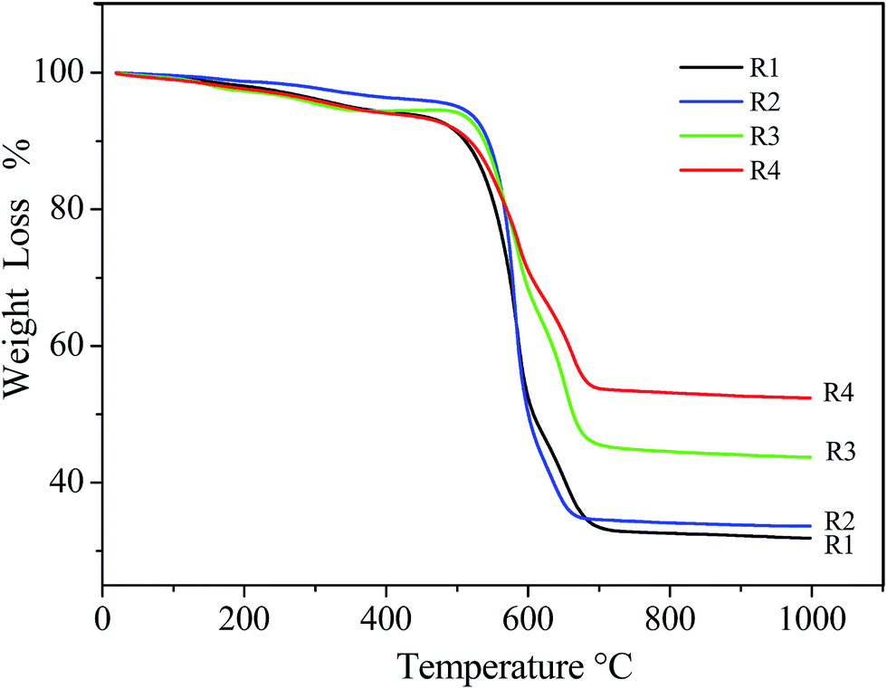 | ||
| Fig. 2 TGA curves of the CNT mat obtained from as-prepared (R1), sprayed (R2) and pumped ferrocene/methanol solution (R3 and R4). | ||
Fig. 3 shows the magnetization curves of R1, R2, R3, and R4 at room temperature. The magnetic performance of the different mats differed based on the ferrocene percentages introduced during the reaction. R1 showed magnetic behavior with a saturation magnetization of 35.4 emu g−1. Spraying ferrocene/methanol solution on the surface of R1 and reheating the sample resulted in a slight higher magnetic behavior with a saturation magnetization of 38.4 emu g−1. When the same volume of ferrocene/methanol solution was pumped in the preparation process, the magnetic behavior suddenly increased, with a high saturation magnetization of 43.2 and 57.3 emu g−1 for R3 and R4, respectively.
 | ||
| Fig. 3 Magnetization curves of the CNT mat obtained from as-prepared (R1), sprayed (R2) and pumped ferrocene/methanol solution (R3 and R4). | ||
Fig. 4a shows the EMI SE of different CNT mats at a frequency range from 1 GHz to 18 GHz. The EMI SE of R1 was 21.2–36.8 dB, and there was a slight improvement (23.8–37.3 dB) when the ferrocene/methanol solution was sprayed on the surface of R1 (R2). While the ferrocene/methanol solution was pumped in the preparation process, the EMI SE of the mat increased to 29.1–45.0 dB (R3) and 40.4–60.3 dB (R4). Table 1 gives a comparison of the mat EMI SE results and other shielding materials,9,13–15,18,19,23,24,28,31 in which the mat has higher EMI SE and thinner thickness than other materials. Considering the density of the mat, the specific EMI SE (the total SE value divided by density) is much higher than other reports, which should be due to composition and morphology of the obtained mat that were changed by added ferrocene/methanol solution. Compared to our previous mat, the electric conductivity and magnetic performance of the mat have been enhanced, and therefore lead to a significant improved EMI SE. In addition, the present mat still displays structural integrity and flexibility. The results showed the present method has potential application to prepare uniform and flexible CNT mat with high EMI SE.
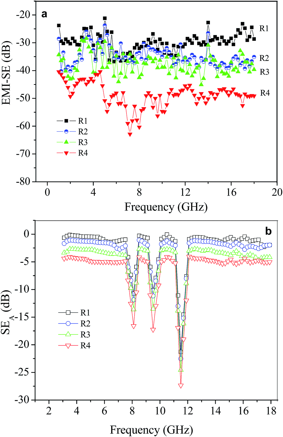 | ||
| Fig. 4 EMI SE (a) and SEA (b) of the CNT mat obtained from as-prepared (R1), sprayed (R2) and pumped ferrocene/methanol solution (R3 and R4). | ||
| Materials | EMI SE (dB) | Frequency range (GHz) | Volume electrical resistivity (Ω cm) | Thickness (mm) |
|---|---|---|---|---|
| SWCNT-epoxy composites9 | 15–20 | 0.5–1.5 | 5.0 | 2 |
| 7 vol% Ni filaments/PES-matrix composites13 | 87 | 1–2 | 2.2 × 10⁻² | 2.8 |
| 7 vol% carbon filaments/PES-matrix composites13 | 32 | 1–2 | 3.78 | 2.8 |
| Nickel-coated carbon fiber14 | 20–33 | 0.5–18 | 0.04 | 0.22 |
| Bare carbon fiber mat15 | 19–22 | 0.3–1.5 | 0.06–0.09 | 0.31 |
| Reduced graphene oxide18 | 18–20 | 0.3–4 | Unknown | 0.015 |
| Ti3SiC2/Al2O3 composites19 | 35–54 | 12.4–18 | Unknown | 1 |
| Flexible graphite23 | 130 | 1–2 | 4.5 × 10⁻⁴ | 3 |
| Ni/hexagonal-ferrite/polymer composites24 | 62–67 | 8.2–18 | Unknown | 2 |
| OMC/fused silica composites30 | 35–45 | 8.2–12.4 | 5 × 10⁻² | 5 |
| Our previous CNT mat28 | 25–31 | 1–18 | 4.5 × 10⁻³ | ∼0.001 |
| Our present CNT mat | 40.4–60.3 | 1–18 | 2.0 × 10⁻³ | ∼0.001 |
The high EMI SE of the ultra-thin mat with 1.0 μm thickness at the electromagnetic wave frequencies (1–18 GHz) can be attributed to significant skin effect and thin skin depth. Electromagnetic radiation penetrates only the near surface region of an electrical conductor at high frequencies, this is known as the skin effect.32 The depth at which the field drops to 1/e of the incident value is called the skin depth (δ), which is given as follows:
| δ = (2/fσμ)1/2 | (1) |
The sheet electrical resistance value of the mats (R1) is approximately 18.6 Ω sq.−1, and the volume electrical resistivity of R1 is 4.5 × 10⁻³ Ω cm, which is much lower than other mats with comparable thickness,28 and the similar electrical resistance from 5 samples that obtained by cutting the same piece of mat showed the uniformity of the mat. Given that a significant amount of iron particles with low electric resistance were deposited randomly in CNT bundles, the sheet and volume electrical resistance of R3 and R4 decreased to 13.2 Ω sq.−1, 3.0 × 10⁻³ Ω cm and 10.8 Ω sq.−1, 2.0 × 10⁻³ Ω cm based on the concentration of ferrocene/methanol solution pumped into reactor. The magnetic permeability on high frequencies will be restricted by Snoek's law:33
| (μ − 1)f = (2γ4πMs)/3 | (2) |
Pumping the ferrocene/methanol solution into the reactor at high temperatures is found to be very effective for the preparation of CNT mats with high magnetic performance. Spray coating with similar volume and concentration of the ferrocene/methanol on the surface of R1 proved ineffective, as the heat supplied to decompose the ferrocene promotes high ferrocene evaporation (seen in ESI Fig. S4†), thereby leading to low surface concentration of iron particles and only a marginal increase in magnetic performance (similar density (0.1 g cm−3) of R1 and R2 also indicated that spray coating is not work for the CNT mat). And the result demonstrated by iron percentage in TGA curve of R1 and R2. The iron percentage of R2 measured by EDS (ESI Fig. S2e†) also demonstrated the result. According to Snoek's law, high saturation magnetization of the prepared samples would yield a high value of (μ − 1)f. Therefore, the skin depth of the obtained CNT mat decreases sharply with high (μ − 1)f from skin effect theory. Moreover, δ of about 0.03 μm, 0.028 μm, 0.025 μm, and 0.02 μm for R1, R2, R3, and R4 can be obtained, respectively. These values are much lower than the mat thickness of 1.0 μm, and may therefore cause the skin effect to become significant. A decrease in skin depth reduces the transmitted power (Pt) compared with incident power (Pi), resulting in a high EMI SE value.34
The EMI attenuation offered by this CNT mat can be hypothesized to depend on three major mechanisms: (1) reflection of the wave from the front face of the shield, in which reflection loss (SER) is the result of interaction between samples in the conducting material (free electron or vacancy) and the electromagnetic field. (2) The absorption loss (SEA) occurs as the wave pass through the shielding material, and (3) the attenuation of multiple internal reflections at various interfaces, called multiple internal reflections loss (SEM).8 Therefore, the EMI SE of a material can be defined as follows:
| SE (dB) = SER + SEA + SEM | (3) |
The value of electrical conductivity (Fig. 2) and saturation magnetization of the mat (Fig. 3) were increased with more iron particles deposited in CNT bundles from R1 to R4. However, the electrical conductivity of the mat increased much faster than that of the saturation magnetization (Δσ/σ much larger than ΔMs/Ms). According to the theory calculation by N. F. Colaneri and L. W. Shacklette,32 SER is related with the value of (σ/μ), which shows larger SER will be obtained for larger electrical conductivity and smaller magnetic permeability of the materials, and consequently, the high electrical conductivity and high magnetic permeability would lead to large values of SEA. Therefore, SER and SEA of the mat were increased from R1 to R4 because more iron particles were deposited. The loss associated with multiple reflections can be ignored (SEM ∼0) when SE of the EMI shielding materials is more than 10 dB.8,35 As a result, the significantly increased EMI SE (40.4–60.3 dB) of the ultrathin mat with highest electrical conductivity and saturation magnetization (R4) at frequency range from 1 GHz to 18 GHz can be obtained.
To clarify the role of electrical conductivity and saturation magnetization of the mat for SER and SEA, S11 (SEA can be obtained through S11) of the mat (from R1 to R4) was measured as a function of the frequency, as displayed in Fig. 4b. The mats of R1, R2, R3, and R4 show the similar curvilinear trends, which contribute to the appearance of three peaks near 8, 9.5, and 11.5 GHz. With increasing percentages of iron particles in the mat (from R1 to R4), the SEA values increase at the same frequency, which includes peaks shown at 8, 9.5, and 11.5 GHz. These findings indicate that SEA was affected by different values of electrical conductivity and saturation magnetization of the mat. In addition, the SER values would increase from R1 to R4, according to the SE and SEA plots shown in Fig. 4a and b. The results are in accordance with the theory calculation of N. F. Colaneri and L. W. Shacklette.32
The current study improved the EMI SE properties of CNT mats using ferrocene. Ferrocene contributes to the electric conductivity and magnetic shielding by decomposition and formation of iron particles on CNTs. Hence, increased ferrocene percentages indicate better EMI SE. However, the saturation of ferrocene in the reaction solution was approximately 20 mg ml−1, which translates to limited iron nanoparticles on the CNT surface. The use of secondary quartz capillary to enhance the ferrocene availability for the reaction is therefore a simple and viable option to obtain high conductive mat with magnetic behaviour. The in situ ferrocene decomposition/iron particle generation reaction, may provide a continuous network of conductive/magnetic surface (Fig. 1b and d). The TGA analysis of modified CNT mats indicate that iron percentages in the mat can be increased when the ferrocene/methanol solution with a concentration of 10 or 20 mg ml−1 was pumped into reactor. In addition, a high preparation temperature would result in a high degree of crystallinity of the prepared iron nanoparticles.36,37 Lattice fringes (Fig. 1d) indicate the highly crystalline structure of the prepared iron particles. ESI Fig. S3† shows that the graphitic structure of the CNTs also improved because of higher reaction temperatures (the intensity ratio of Raman spectroscopy IG/ID is 5.6 in previous study).
In the experiment on R4, when ferrocene/methanol solution was pumped into the reactor, the low electric resistance, high magnetic performance, and EMI SE of 10.8 Ω sq.−1, 2.0 × 10⁻³ Ω cm, 57.3 emu g−1, and 40.4–60.3 dB, respectively, can be obtained. This suggests that the ferrocene pumped using a secondary quartz capillary process to be an effective way to introduce the catalyst precursor, which on decomposition gives rise to iron atoms in the reactor, even at high reaction temperatures. However, when the change is induced, the addition of carbon source notably remains the same (methanol in the reactor cannot decompose in the experiments29). The improved electric conductivity and saturation magnetization of the formed CNT mats may be ascribed to the increased iron particles in the reactor. And more electromagnetic waves would be reflected due to increased conductivity of the mat. In addition, some energy from electromagnetic wave could be absorbed by the rearrangement of magnetic dipole moment of the mat. Therefore, the EMI SE of the mats could be improved (Fig. 4a and b).
4. Conclusions
The present study shows that the electric conductivity, saturation magnetization, and EMI SE of free-standing mats can be improved by the addition of ferrocene at increased reaction temperatures. The additional ferrocene that was pumped by the secondary quartz capillary decomposes to form a slew of iron particles during the experimental process. This effect consequently enables higher electric conductivity and magnetic particle concentration in mat, a result which cannot be obtained under ferrocene limited reaction solutions. In addition, formation of graphitic structure of the prepared CNTs also improved at high temperatures. Consequently, the free-standing CNT mats obtained through this method have better EMI SE than the currently available state of the art CNT mats.Acknowledgements
This work was supported by the National Natural Science Foundation of China (51202095 and 51264010), the Department of Science & Technology of Jiangxi Province (20153BCB23011, GJJ150617), the program for Excellent Young Talents, JXUST, and Open Research Project of the State Key Lab of Millimeter Waves (K201218).Notes and references
- P. S. Neelakanta and K. Subramaniam, Adv. Mater. Processes, 1992, 141, 20–25 CAS.
- S. H. Wen and D. D. L. Chung, Cem. Concr. Res., 2004, 34, 329–332 CrossRef CAS.
- P. C. P. Wantts, W. K. Hsu, A. Barnes and B. Chambers, Adv. Mater., 2003, 15, 600–603 CrossRef.
- J. M. Thomassin, C. Pagnoulle, L. Bednarz, I. Huynen, R. Jerome and C. Detrembleur, J. Mater. Chem., 2008, 18, 792–796 RSC.
- R. D. Leach and M. B. Alexander, Electronic systems failures and anomalies attributed to electromagnetic interference, NASA Reference Publication, 1995 Search PubMed.
- Y. J. Chen, Y. Li and B. T. T. Chu, Composites, Part B, 2015, 70, 231–237 CrossRef CAS.
- M. Jalali, T. Molière, A. Michaud and R. Wuthrich, Composites, Part B, 2013, 50, 309–317 CrossRef CAS.
- R. Kumar, S. R. Dhakate, P. Saini and R. B. Mathur, RSC Adv., 2013, 3, 4145–4151 RSC.
- N. Li, Y. Huang, F. Du, X. B. He, X. Lin, H. J. Gao, Y. F. Ma, F. F. Li, Y. S. Chen and P. C. Eklund, Nano Lett., 2006, 6, 1141–1145 CrossRef CAS PubMed.
- B. P. Singh, V. Choudhary, P. Saini and R. B. Mathur, AIP Adv., 2012, 2, 022151 CrossRef.
- Y. Huang, N. Li, Y. F. Ma, F. Du, F. F. Li, X. B. He, X. Lin, H. J. Gao and Y. S. Chen, Carbon, 2007, 45, 1614–1621 CrossRef CAS.
- X. C. Luo and D. D. L. Chung, Composites, Part B, 1999, 30, 227–231 CrossRef.
- D. D. L. Chuang, Carbon, 2001, 39, 279–285 CrossRef.
- H. R. Kim, K. Fujimori, B. S. Kim and I. S. Kim, Compos. Sci. Technol., 2012, 72, 1233–1239 CrossRef CAS.
- T. Kim and D. D. L. Chung, J. Mater. Eng. Perform., 2006, 15, 295–298 CrossRef CAS.
- S. K. Hong, K. Y. Kim, T. Y. Kim, J. H. Kim, S. W. Park, J. H. Kim and B. J. Cho, Nanotechnology, 2012, 23, 455704 CrossRef PubMed.
- B. Shen, W. T. Zhai and W. G. Zheng, Adv. Funct. Mater., 2014, 24, 4542–4548 CrossRef CAS.
- P. Kumar, F. Shahzad, S. Yu, S. M. Hong, Y. H. Kim and C. M. Koo, Carbon, 2015, 94, 494–500 CrossRef CAS.
- S. L. Shi, L. Z. Zhang and J. S. Li, J. Appl. Phys., 2008, 103, 124103 CrossRef.
- J. S. Im, J. G. Kim, S. H. Lee and Y. S. Lee, Mater. Chem. Phys., 2010, 124, 434–438 CrossRef CAS.
- Y. E. Moon, J. Yun and H. I. Kim, J. Ind. Eng. Chem., 2013, 19, 493–497 CrossRef.
- J. M. Thomassin, C. Jérôme, T. Pardoen, C. Baily, I. Huynen and C. Detrembeur, Mater. Sci. Eng., R, 2013, 74, 211–232 CrossRef.
- X. Luo and D. D. L. Chung, Carbon, 1996, 34, 1293–1294 CrossRef.
- B. W. Li, Y. Shen, Z. X. Yue and C. W. Nan, Appl. Phys. Lett., 2006, 89, 132504 CrossRef.
- Z. P. Wu, D. M. Cheng, W. J. Ma, J. W. Hu, Y. H. Yin, Y. Y. Hu, Y. S. Li, J. G. Yang and Q. F. Xu, AIP Adv., 2015, 5, 067130 CrossRef.
- Z. P. Wu and J. N. Wang, Phys. E, 2009, 42, 77–81 CrossRef.
- Z. P. Wu, Q. F. Xu and J. N. Wang, J. Mater. Sci. Technol., 2010, 26, 20–26 Search PubMed.
- Z. P. Wu, M. M. Li, Y. Y. Hu, Y. S. Li, Z. X. Wang, Y. H. Yin, Y. S. Chen and X. Zhou, Scr. Mater., 2011, 64, 809–812 CrossRef CAS.
- Z. P. Wu, J. N. Wang and J. Ma, Carbon, 2009, 47, 324–327 CrossRef CAS.
- X. Y. Ma, Q. Zhang, Z. C. Luo, X. Lin and G. H. Wu, Mater. Des., 2016, 89, 71–77 CrossRef CAS.
- J. C. Wang, C. S. Xiang, Q. Liu, Y. B. Pan and J. K. Guo, Adv. Funct. Mater., 2008, 18, 2995–3002 CrossRef CAS.
- N. F. Colaneri and L. W. Shacklette, IEEE Trans. Instrum. Meas., 1992, 41, 291–297 CrossRef.
- J. L. Snoek, Physica, 1948, 14, 204–207 CrossRef.
- J. Joo and C. Y. Lee, J. Appl. Phys., 2000, 88, 513–518 CrossRef CAS.
- M. Verma, A. P. Singh, P. Sambyal, B. P. Singh, S. K. Dhawan and V. Choudhary, Phys. Chem. Chem. Phys., 2015, 17, 1610–1618 RSC.
- C. H. Chia, S. Zakaria, M. Yusoff, S. C. Goh, C. Y. Haw, S. Ahmadi, N. M. Huang and H. N. Lim, Ceram. Int., 2010, 36, 605–609 CrossRef CAS.
- M. J. Sharif, M. Yamauchi, S. Toh, S. Matsumura, S. I. Noro, K. Kato, M. Takata and T. Tsukuda, Nanoscale, 2013, 5, 1489–1493 RSC.
Footnote |
| † Electronic supplementary information (ESI) available. See DOI: 10.1039/c6ra11507a |
| This journal is © The Royal Society of Chemistry 2016 |